Precision Mold Design & DFM Analysis — Free 24-Hour Feedback
Free 24-hour DFM feedback on your part drawing — manufacturability review, gate and runner design, mold flow analysis, steel selection and quotation. Design support for injection, stamping and die casting tooling.
- 24-Hour DFM Review
- Mold Flow Analysis
- Gate and Runner Design
- Steel Selection
- Design for Manufacturing
- Full 3D to 2D
Fast Response within 2 HoursNDA ProtectedSTEP / IGES / X_T / DWG
Trusted Tier-1 & OEM Standards:
SERVICE SCOPE & CAPABILITIES
Complete Mold Design & DFM Engineering Scope
From first drawing review to finished detail drawings — DFM analysis, Moldflow simulation, 3D mold design and 2D manufacturing drawings delivered by engineers with 15+ years in precision tooling.
DFM & FEASIBILITY
Design for Manufacturability Review
- Free 24-hour DFM feedback with firm quotation
- Parting line, draft angle and wall thickness analysis
- Undercut detection and slide / lifter recommendations
- Gate location and runner balance optimization
MOLDFLOW ANALYSIS
Injection Molding Simulation
- Fill, packing and cooling simulation before steel cutting
- Weld line, air trap and sink mark prediction
- Shrinkage compensation and warpage control
- Cycle time and cooling layout optimization
3D MOLD DESIGN
Full 3D Mold Structure Design
- Complete moldbase, core and cavity design in 3D
- Ejector, slide, lifter and cooling channel layout
- Standard parts selection (HASCO / DME / MISUMI compatible)
- Designed in UG NX / ProE with full assembly BOM
2D DRAWINGS
Detail & Manufacturing Drawings
- 2D detail drawings for every plate, insert and component
- GD&T per ASME Y14.5 with critical dimensions flagged
- EDM and grinding sketches with datum setup
- Approval drawings issued before any steel is cut
ENGINEERING & TECHNICAL SUPPORT
Free DFM & Moldflow Engineering Before Steel Cutting
Every part file is reviewed by engineers with 15+ years in precision mold making. We return practical, geometry-specific recommendations — not a generic checklist — within 24 hours.
Four DFM Checks We Run on Every Drawing
Moldability & Parting Line
Part orientation, split position and parting line placement reviewed against cosmetic surfaces, flash visibility and mold complexity.
Draft, Wall & Radius Verification
All vertical faces checked against required draft (0.5–2° plus texture allowance), wall uniformity for sink and warpage, and fillet radii for stress and tool wear.
Moldflow & Gate Optimization
Fill simulation for weld lines, air traps and short shots; gate location and runner balance tuned for your resin and target cycle.
Tolerance & Cost Feasibility
Unnecessary tight tolerances and finishes flagged with cost impact, and achievable limits confirmed against our ±0.005 mm machining standard.
6-Step Design Collaboration Flow
Send Your Drawing
STEP, IGES, X_T, DWG or PDF of the part — 3D preferred for fastest review.
24H DFM Review
Geometry, material, tolerance and volume analyzed; DFM report with quotation returned within one business day.
Recommendations
Mold layout, gate and runner plan, cavity count, steel selection, lead time and cost — before any design work starts.
3D Mold Design
On approval, full 3D design with Moldflow simulation and cooling layout, followed by approval drawings.
Build & Trial
Machined, vacuum heat treated and assembled in-house; trialed under our supervision with T1 samples and CMM report.
Deliver & Support
Mold shipped with samples, dimensional report and full documentation; ongoing technical support included.
Send Your Part Drawing for a Free DFM Report
Our tooling engineers return a structured DFM analysis and firm quote within 24 hours — free, NDA protected.
.STEP | .IGES | .X_T | .DWG | .PDF (Max 100MB)
ENGINEERING CAPABILITIES & DESIGN SOFTWARE
Precision Mold Design & Manufacturing Capabilities
Design & Manufacturing Accuracy Standards
| Specification Parameter | Automotive & EV Standard | High-Precision Custom |
|---|---|---|
| Machining Tolerance | ±0.005 mm (Standard) | Up to ±0.002 mm (Critical Features) |
| Surface Roughness | Ra 0.4 µm | Up to Ra 0.05 µm (Mirror EDM) |
| Min. EDM Radius | R 0.05 mm | R 0.02 mm (Micro Detail) |
| Max. Mold Dimensions | 1200 × 800 × 600 mm | Multi-Cavity & Large Insert Tooling |
| Mold Steels | NAK80, S136, H13, SKD61 | DC53, Calmax, Stavax |
| CAD / CAM / CAE Software | UG NX · ProE · Mastercam | Moldflow Analysis · CMM Programming |
Key In-House Design & Processing Equipment
UG NX / ProE / Moldflow
Full 3D mold structure design, Moldflow fill and cooling simulation, and GD&T detail drawings done in-house.
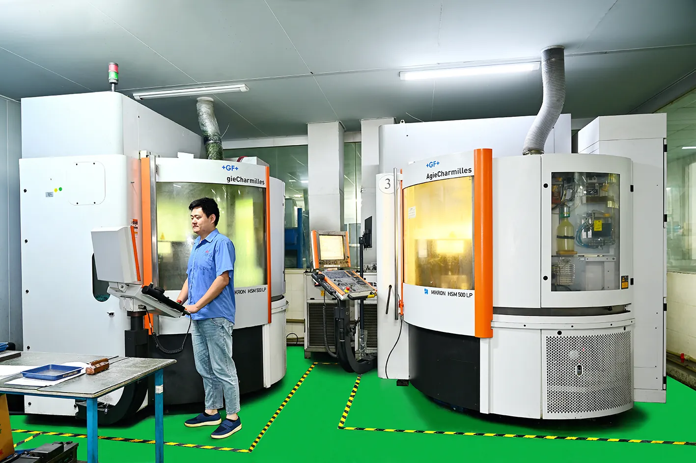
5-Axis & High-Speed CNC
Complex cavities and hardened-steel finishing with collision-checked toolpaths and through-spindle coolant.
Sodick Wire / Sinker EDM & Jig Grinding
R 0.05 mm internal radii, mirror finishes and matched cavity sets held to ±0.002 mm.
ZEISS CMM & Vision Measuring
100% CMM dimensional verification of every cavity, insert and critical feature before delivery.
From CAD to Production Mold
DFM & Moldflow
CAD evaluation & gating design
Design Approval
3D design & 2D detail drawings
Machining & EDM
Precision CNC, EDM & heat treatment
T1 Trial & Delivery
CMM inspection, sampling & PPAP
MOLD STEEL & MATERIAL COMPLIANCE
Certified Mold Steels & Material Traceability
Every mold is quoted and built with traceable, certified steel — material selection matched to your part resin, volume and finish requirements.
Proven Mold Steel Grades
Core & Cavity Steels
Stainless & Corrosion-Resistant
Standard Components
In-House Vacuum Heat Treatment
Hardness Ranges
Processes
Verification
Full Material Documentation
Deliverable Checklist
Need Help Selecting the Right Mold Steel?
Our engineers match steel grade, hardness and surface treatment to your part resin, volume and cosmetics.
🔒 Free DFM & Material Advice
QUALITY ASSURANCE & INSPECTION
Mold Design Verified by Precision Inspection
Design review, machining and final inspection all happen in-house — every mold ships with a CMM dimensional report matching the approved design.
 INSPECTION HARDWARE
Sub-Micron Metrology Lab
- ZEISS CMM inspection down to ±0.001 mm for cavities, inserts and mating surfaces
- Optical measuring projectors at 0.001 mm resolution for pins, draft angles and thread positions
- Vickers hardness and surface roughness verification of heat treated steels
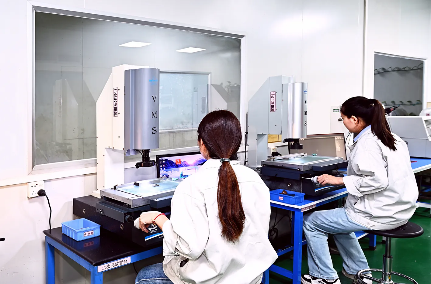 QA PROTOCOL
Three-Stage Quality Control
- IQC: XRF spectrometer verification of every steel lot before machining
- IPQC: First-piece checks after every major setup change on CNC, EDM and grinding
- FQC: 100% critical-dimension inspection before trial and shipment
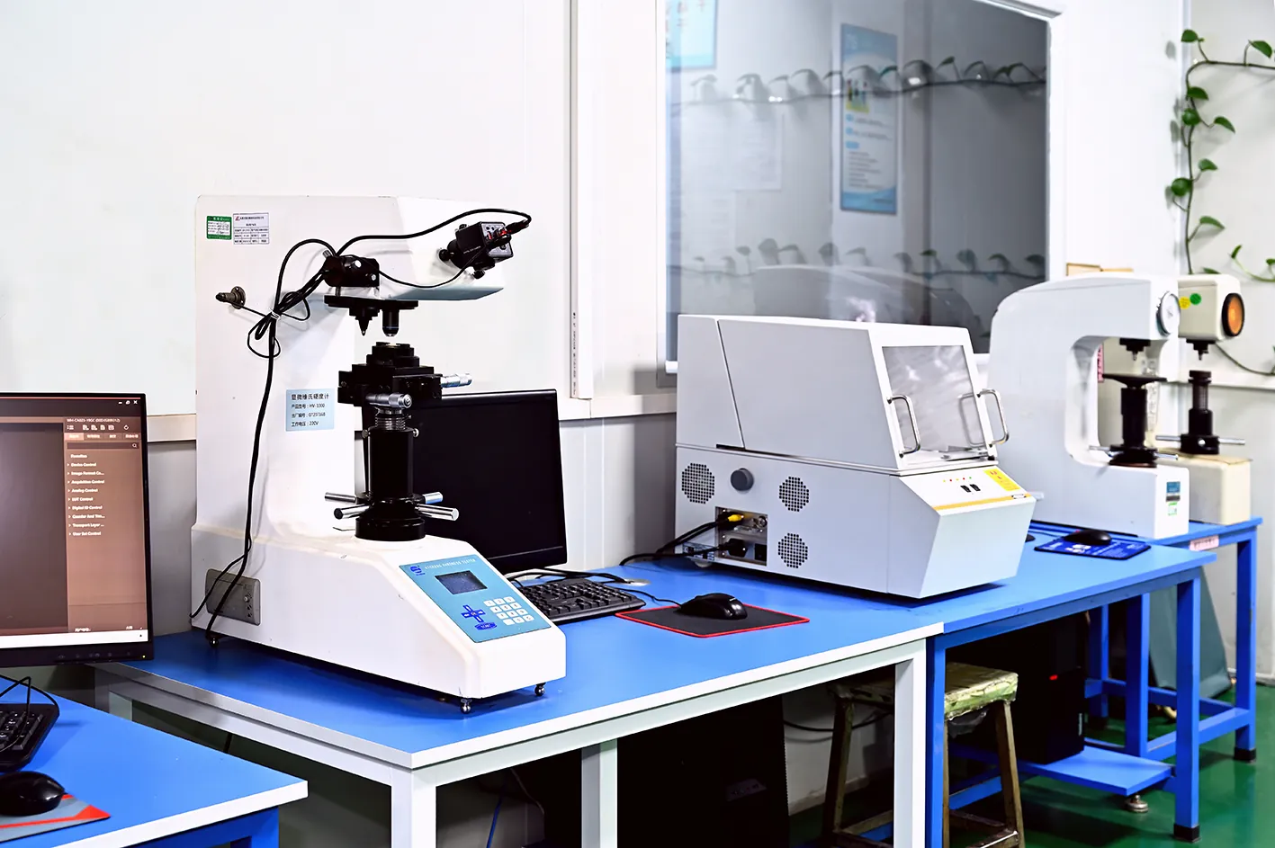 DOCUMENTATION
PPAP & Trial Reports
- Ballooned CAD drawings matched 1:1 with CMM inspection data
- First Article Inspection Reports (FAIR) with T1 samples
- Mill test certificates (EN 10204 3.1) and heat treatment logs on every order
Download Sample Quality Control & Inspection Reports
Review our standard CMM inspection sheet, Material Composition Certificate, and RoHS report templates.
FREQUENTLY ASKED QUESTIONS
Mold Design & DFM Service FAQ
Common technical and commercial questions about our free DFM review, mold design workflow and delivery.
Yes. For part drawings submitted through our inquiry form, DFM review and quotation are free within 24 hours.
STEP, IGES, STL, X_T, DWG, PDF and native CAD on request. 3D files speed up the review significantly.
Both. We provide complete 3D mold design with Moldflow analysis, or build to your existing design with DFM verification.
Manufacturability findings, mold layout, cavity recommendation, gate and runner plan, steel selection, lead time and quotation.
Yes — we flag draft, wall thickness, radii and texture issues that add tooling cost, and suggest changes that save money without affecting function.
DFM feedback within 24 hours; 3D mold design with drawings typically 3–7 days after approval; complete molds 2–5 weeks depending on size and complexity.
Ready to Start Your Mold Design Project?
Send us your part drawing today. Our tooling engineers return a free DFM report and detailed quotation within 24 hours.
🔒 100% Confidential | NDA Protected | Free 24H DFM
RELATED MOLD COMPONENTS