
How to Choose Mold Cavity Count: Output, Cost and Risk Balance
Table of Contents
A buyer approves 4 cavities against a 2.5 million part per year forecast, and the program ramps to 5 million in year two. The tool then runs 4,000 hours at 96 percent utilization, and overtime adds 12 percent to the part cost. A duplicate tool ordered at kickoff would have cost 40,000 dollars and 8 to 10 weeks of lead time. Ordered late, it costs both, plus a line-down risk on the customer's assembly schedule. Cavity count is the first number in a tool concept and the last one anyone wants to change.
This article works the cavity equation, the machine constraint loop, the cost curve and the risk decision.
The Snapshot
- The equation sets the floor. 2 million parts a year, 4,000 machine hours, a 20 second cycle and 97 percent yield give 2.9 cavities, which rounds up to 4.
- Cost rises 15 to 35 percent per doubling. A 16 cavity tool costs roughly 2.4 times a single cavity tool, not 16 times, because plates, cooling and ejection are shared.
- The machine gates the layout. Shot size must sit between 20 and 80 percent of barrel capacity. Clamp force runs 1.8 to 2.2 tonnes per square decimetre of projected area.
- Count multiplies the process window. A peak cavity pressure spread above 10 percent flags imbalance, and capability is judged per cavity at Cpk 1.33 rather than pooled.
The Demand Equation
The cavity equation is a capacity sum with four inputs. Cavities equal annual demand divided by the product of available machine hours, shots per hour and yield.
Take a program at 2 million parts a year with no growth assumed yet. Available hours: 250 working days at two 8 hour shifts, which is 4,000 hours. A 20 second cycle gives 180 shots an hour. A yield of 97 percent covers short shots, flash, start-up scrap and contamination. The product of 4,000 hours, 180 shots and 0.97 yield is 698,400 good parts per cavity per year.

Demand of 2 million divided by 698,400 gives 2.9 cavities. The arithmetic answer is not yet a tool concept, because cavity counts are built in symmetric steps: 1, 2, 4, 8, 16 and 32. Round 2.9 up to 4.
Two inputs move faster than most buyers expect. A third shift raises available hours from 4,000 to 6,000 and cuts the required count by a third, which is cheaper than extra cavity steel. Shortening the cycle from 20 to 15 seconds raises shots from 180 to 240 an hour and drops the requirement from 2.9 cavities to 2.1.
Yield matters at the margin. A process at 99 percent yield makes about 115,000 more good parts a year on a 4 cavity tool than one at 95 percent. That gap is often worth more than an added cavity. Fill the equation before the steel is quoted, because a count taken from a forecast alone is a guess with a purchase order attached.
The Machine Constraint Loop
A count from the equation is a wish. The machine loop decides whether the plant can grant it, and it tests three limits at the same time.
Shot size. The combined shot of all cavities plus the runner should sit between 20 and 80 percent of the barrel injection capacity. Below 20 percent, melt residence time climbs and a glass-filled resin starts to degrade between shots. Above 80 percent, the screw has no injection rate reserve and cushion control gets noisy. A 141 cubic centimetre shot in a 450 cubic centimetre barrel is 31 percent and sits in the middle of the band.
Clamp force. Projected area in square decimetres times a factor of 1.8 to 2.2 tonnes per square decimetre gives the tonnage a layout needs. Use 2.2 for low-viscosity glass-filled grades that fill at high pressure, and 1.8 for thick walls filled slowly. A 16 cavity connector layout projects about 9 square decimetres and needs 18 tonnes, which is a fraction of a 200 tonne press.

Platen, tie bars and daylight. The cavity layout plus 40 to 90 mm of steel on every side sets the mold base. That base must fit between the tie bars and inside the platen, and daylight must clear the part height plus the sprue picker. This limit rejects more high-count layouts than tonnage does.
Adding cavities raises shot weight and projected area together, so a count that fits the barrel can still fail on the platen. Test every candidate count against all three limits, on presses the customer already owns. Moving a 16 cavity tool up to a 380 tonne machine can add 25 to 45 percent to the hourly rate. That step up in machine class can erase the per-part saving.
Two checks decide most cases: clamp tonnage from projected area, and machine matching on shot size, platen and daylight.
Diminishing Returns by Cavity Count
The economics of scale arrive fast and then flatten. The table below shows the shape most programs follow at a 20 to 45 second cycle on two shifts.
| Cavity count | Demand band, two shifts | Tool cost vs 1 cavity | Main risk at this count |
|---|---|---|---|
| 1 | Under 150,000 parts a year | 1.0x | Machine hours dominate the part cost |
| 2 | 150,000 to 800,000 | 1.15 to 1.35x | Low; watch ejection balance |
| 4 | 600,000 to 2 million | 1.4 to 1.65x | Runner balance starts to matter |
| 8 | 1.5 to 4 million | 1.7 to 2.1x | 1 percent weight window, gate wear |
| 16 | 3 to 8 million | 2.0 to 2.6x | Process window and per-cavity Cpk |
| 32 or more | Above 8 million | 2.5 to 3.4x | Maintenance load and sensor cost |
← swipe to scroll →
Table note: demand bands assume two shifts, 4,000 hours a year and 97 to 98 percent yield. Tool cost multipliers are cumulative against a single cavity tool and follow the 15 to 35 percent per doubling rule.
Payback is the test, not tool price. Going from 4 to 8 cavities on a 1 million part per year program removes 708 machine hours a year. At 55 dollars an hour, those hours are worth about 39,000 dollars. If the 8 cavity tool costs 20,000 dollars more, the premium pays back in about 6 months.
The same move from 8 to 16 cavities at that volume saves only 354 hours, or 19,500 dollars a year, against a similar premium. Payback stretches past a year, and the extra balance work lands on the same program. Two to four cavities normally pay back inside the first year above 400,000 parts. Eight to 16 cavities need automotive volume before the machine hours they free are worth their steel.
Family molds hide the same math behind a different name. When the cavities hold different parts, the count no longer divides a single demand figure. The smallest part then sets the balance risk for the whole tool. That is a separate decision, covered in the family mold guide.
Per-Cavity Cost Reality
Doubling the cavity count does not double the tool price. The base plate, clamping plates and the hot runner manifold are shared across every cavity. So are the controller, the cooling manifold, the ejection plates and the machine itself.
What scales is the working steel. Each added cavity brings an insert and machining hours on a jig grinder or an EDM. It also adds a gate or nozzle drop, an ejection circuit and a set of cooling channels. That lands at 15 to 35 percent of the previous tool price per doubling.
A typical curve for a hot runner engineering part runs 1.0 for a single cavity. It reaches 1.15 to 1.35 at 2 cavities, 1.4 to 1.65 at 4, 1.7 to 2.1 at 8 and 2.0 to 2.6 at 16. Steel is the cheap part of the decision.
The expensive part is verification and balance. Mold geometry is held at +/-0.005 mm, and at +/-0.002 mm on EDM work and jig-grinding. Every cavity needs its own CMM report, its own gate trim and its own weight check. A 16 cavity tool takes 5 to 8 more trial hours than a 2 cavity tool just to reach a stable fill.
Per-part cost falls only when the machine hours are actually consumed. Cavities do not reduce material cost, cycle time or the labour per shot. A 16 cavity tool that runs 400 hours a year carries the same steel payment as one that runs 4,000.
Balancing Flow at High Count
At 8 cavities and above, balance is a design deliverable rather than a tuning outcome. The target is a cavity to cavity weight spread inside 1 percent of the mean, measured over 30 consecutive shots at the T1 trial.
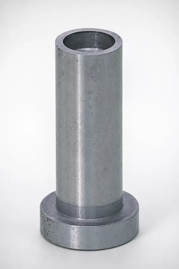
Cold runner tools reach that target with stepped runner diameters. Branches that carry melt to the far cavities run 5 to 10 percent larger in diameter than the near ones. Every junction gets a full radius. A 16 cavity layout with a 6.0 mm main, a 5.5 mm secondary and a 5.0 mm tertiary branch is a common step pattern. The gate land is then trimmed cavity by cavity.
Hot runner tools balance with valve gate sequencing instead. The drops furthest from the sprue open 0.2 to 0.4 seconds first, and each nozzle zone holds +/-1 °C of setpoint. A pressure sensor at the nozzle tip is the fastest way to see which drop starves.
Fill timing is the second target. If the fastest cavity freezes 0.3 seconds before the slowest, the packing profile differs across the tool. The weight spread then opens in the last second of hold, when no process setting can close it.
Three sources of drift appear after the first 50,000 shots. They are gate wear on the fastest cavity, cooling flow differences of 10 to 20 percent, and shear history at the manifold inlet. A gate that opens 0.1 mm wider than its neighbours can pull 2 percent of the shot weight into one cavity. On a 12 g part that is 0.24 g, which moves a 25 mm dimension on a glass-filled resin by 0.02 to 0.05 mm. The runner and gate work that keeps a high count level is set out in the multi-cavity balance guide.
Quality and Capability at Count
Capability is judged cavity by cavity. Automotive and medical programs working to IATF 16949 expect Cpk 1.33 or better on every critical dimension in every cavity. Pooled output from the whole tool does not satisfy that.
Pooling hides the failure mode. Sixteen cavities with one sitting 0.1 mm off the group can show a pooled Cpk of 1.5 while that cavity runs at 0.9. Sorting finds it eventually, usually after a containment event rather than before one.

Peak cavity pressure is the early warning. A spread above 10 percent between cavities flags a fill imbalance before dimensions drift, and it is the cheapest signal to trend every 10,000 shots.
Sample size follows from the index. A Cpk 1.33 claim at 95 percent confidence needs about 60 measurements per critical dimension per cavity. Three critical dimensions across 16 cavities is 2,880 measurements, which is why capability work belongs in the plan before the first production run.
Cavity identification makes all of it traceable. Number every cavity on the tool and mark the matching position on the part. A weight or dimension outlier can then be traced to a drop, a gate or a cooling circuit without a full strip.
Tolerance class narrows the choice. Features held under 0.1 mm total tolerance are safer in a 2 to 4 cavity tool. Features between 0.1 and 0.3 mm suit 8 cavities. Wider tolerances can carry 16 cavities or more without a capability argument.
Spreading Risk Across Tools
One 16 cavity tool is a single point of failure for a whole program. A stuck part that bends an ejector, a cracked core or a gate that washes out stops 100 percent of output for the repair window.
Size the exposure. A 16 cavity tool at a 28 second cycle produces about 2,057 parts an hour. A five day repair at 16 production hours a day is 164,000 parts of lost output, plus a probable line-down claim from the customer.
Four identical 4 cavity tools change the arithmetic. Each carries 25 percent of demand, so a failure costs 25 percent of output while the remaining presses absorb part of the gap with overtime. Standard components ship in 3 to 7 days, so most repairs are measured in days rather than weeks.
The trade is tool cost. Four 4 cavity tools cost roughly 2.5 times one 16 cavity tool for the same 16 cavities of output. The base plate, manifold, controller and cooling hardware are paid for four times. In return the program gains a 75 percent capacity fallback and four presses that can each run on a smaller machine class.
Duplicating small tools wins when the part sits on the customer's critical path and the fleet has spare presses. One large tool wins when machine hours are the scarce resource, because four presses consume four setups and four sets of operator attention.
A cheaper middle path sits inside the single tool. A spare cavity insert and core, cut at the original build, shortens the fix. A 2 to 5 week replacement tool becomes a 2 to 4 day insert change. Plan it for the cavity that sees the worst fill or the heaviest wear.
The Decision Worksheet
Work the five inputs below in order. Each one can overrule a cavity count that came out of the equation.
1. Demand and growth. Take the contracted annual volume and apply a 1.5 factor across the program life. A count that serves year one demand exactly will be short in year two, and late steel costs more than planned steel.
2. Machine fleet. List shot capacity, clamp tonnage, platen size and tie bar spacing for the presses the customer actually runs. The count that fits the fleet usually beats the count that is cheapest in steel.
3. Size and tolerance class. Parts above 50 g or with a wall above 2 mm fill more slowly, need more hold time and resist balance. Features under 0.1 mm total tolerance push the count down to 2 to 4 cavities.
4. Material. Low-viscosity glass-filled grades turn small fill differences into weight differences. High-shrink semi-crystalline resins need the balance target held from the first shot rather than after 50,000.
5. Contract and downtime cost. A one year purchase order with a 250,000 dollar line-down penalty per shift argues for duplicated tools. A three year contract with soft delivery windows argues for fewer and larger tools.
Then compute, test and cost. Run the equation and round up to the nearest standard count. Test that count and the one below it inside the machine loop. Price both on the 15 to 35 percent curve, then apply the growth factor.
Re-run the worksheet when demand passes 90 percent of a two shift line. Other triggers are a tighter tolerance class or a new press class in the fleet.
A DFM review before the quote removes most of this risk. DieStrike returns quoted cavity counts with the tool concept, so the arithmetic travels with the price.
Worked Example: A 16 Cavity Connector Tool
The part is a 12 g connector in glass-filled nylon at 8 million pieces a year. The target cycle is 28 seconds, and the plant runs two shifts across 250 days.
Step one, the equation. A 28 second cycle gives 128.6 shots an hour. Four thousand hours times 128.6 shots times 0.98 yield is 504,000 good parts per cavity a year. Demand of 8 million divided by 504,000 gives 15.9 cavities, which rounds up to 16.
Step two, shot size. Sixteen cavities of 12 g is 192 g of plastic, or 141 cubic centimetres at 1.36 g per cubic centimetre for glass-filled nylon. That is 31 percent of a 450 cubic centimetre barrel, inside the 20 to 80 percent band.
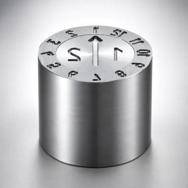
Step three, machine. A 4 by 4 layout on an 80 mm pitch occupies 320 mm by 240 mm. With margins, the projected area reaches about 9 square decimetres. At 2.0 tonnes per square decimetre the clamp demand is 18 tonnes. The 200 tonne press is chosen for its 610 mm platen and the shot delivery of a 450 cubic centimetre screw, not for tonnage.
Step four, cost. The 16 cavity tool lands at roughly 2.4 times a single cavity tool, following four doublings at 15 to 35 percent each. Material cost, cycle time and labour per shot are unchanged by the count.
Step five, headroom. Sixteen cavities need 3,968 of the 4,000 available hours, which is 99 percent of a two shift line at 8 million pieces. Growth to 12 million pieces a year would need 5,952 hours at this count, or 1.5 lines.
The contract decides the answer. A signed three year volume justifies a 32 cavity tool at 2,976 hours. A one year order justifies a second 16 cavity tool held in the plan.
Worked Example: A 2 Cavity Housing Tool
The part is a 90 g ABS housing, 220 mm by 140 mm, with a 2.5 mm wall and 400,000 pieces a year. The cycle is 45 seconds.
A 45 second cycle gives 80 shots an hour. Four thousand hours times 80 shots times 0.98 yield is 313,600 good parts per cavity a year. Demand of 400,000 divided by 313,600 gives 1.28 cavities, which rounds up to 2.
Check one cavity before accepting the answer. A single cavity would need 5,102 hours, or 128 percent of a two shift year, which forces a third shift or a second tool. Four cavities would cut the load to 1,276 hours, but machine hours are not scarce at this volume. The extra cavities add 25 to 35 percent of tool cost for capacity the contract never uses.
Shot size confirms the count. Two cavities of 90 g plus a 30 g cold runner is a 210 g shot. At 1.05 g per cubic centimetre for ABS, that is 200 cubic centimetres of melt. That is 63 percent of a 320 cubic centimetre barrel, inside the band with room for a larger sprue.
Clamp is not the constraint. Two 220 mm by 140 mm parts project about 7.4 square decimetres with the sprue. At 2.0 tonnes per square decimetre, that is close to 15 tonnes of clamp. The press is selected for the 550 mm platen that fits a 600 mm mold base, and the daylight that clears the part.
The load at 2 cavities is 2,551 hours a year, or 64 percent of a two shift line. That leaves room for maintenance and a trial slot. Re-run the worksheet when demand passes 560,000 pieces a year, because that is 90 percent of the line at this count.
The Bottom Line
Cavity count is a capacity calculation first and a cost decision second. The demand equation turns annual volume, machine hours, cycle time and yield into a number. Rounding rules then turn that number into 2, 4, 8 or 16.
The machine loop then decides what the plant can actually run. Shot size must sit between 20 and 80 percent of barrel capacity, and clamp at 1.8 to 2.2 tonnes per square decimetre. The platen and daylight must also fit the layout.
Cost rises 15 to 35 percent per doubling, so steel is rarely the reason to stop at a low count. The real limits at 8 cavities and above are balance inside 1 percent by weight and per cavity capability at Cpk 1.33. A peak pressure spread under 10 percent is the third.
Where the part sits on the customer's critical path, split the volume across duplicated small tools. Cut spare inserts at the original build rather than one large block of steel. The count that survives a ramp, a repair and a capability audit is the one that was computed rather than assumed.
DieStrike builds production and prototype molds to IATF 16949, with mold tolerance held at +/-0.005 mm and +/-0.002 mm on EDM and jig-grinding. Cavity steel reaches HRC 62 across 120+ machines, with standard components in 3 to 7 days and tool lead times of 2 to 5 weeks.
KEEP READING
Related Reading
How to Balance Multi-Cavity Molds: Runner, Gate and Cooling
Runner sizing, gate trim and cooling balance so 8 or 16 cavities hold a 1 percent weight spread.
Read articleArticleHow to Design Family Molds: Runner Balance for Unequal Parts
What changes when the cavities hold different parts, and where family tooling hides imbalance risk.
Read articleArticleHow to Calculate Clamp Tonnage: Projected Area, Cavity Pressure, Safety Margin
Projected area math that tells you which press class a cavity layout actually needs.
Read articleServiceInjection Mold Manufacturing
IATF 16949 mold building with DFM feedback in 24 hours and 2 to 5 week lead times.
Read articleNEXT STEP
Ready to Start Your Mold?
Send us your element dimensions or part numbers — our team responds within 24 hours with pricing and lead time.

Written by
Ray ChanMold Buyer's Guide Author · Precision Mold Manufacturing Specialist. Ray helps global importers, distributors and OEMs source factory-direct molds and mold parts.