
GD&T for Mold Buyers: Datums, Flatness and Callouts
Table of Contents
One connector bracket print came back quoted at two prices by two shops: $48,000 and $96,000 for the same 16-cavity mold. The difference was not steel or lead time. One callout read profile 0.2 mm between datums A and B. The other read profile 0.2 mm with no datum reference, which forces the moldmaker to control every point of that surface in free space. The undated profile doubled grinding hours, added two extra CMM programs and put the tool at risk of failing its own inspection plan.
Geometric dimensioning and tolerancing is the language that decides what a mold shop must build, how it verifies the build and what it charges you. Buyers who cannot read that language sign off on drawings that quietly carry the most expensive interpretation. This guide covers the callouts that move mold price the most: datum frames, flatness, orientation, profile, position with bonus tolerance and surface finish. It is written for the person approving the print, not the person programming the CMM.
The Snapshot
- Datum A is normally the parting face plane, B a locating edge and C a hole or pin that stops rotation, in that order of precedence.
- Flatness callouts on mold-relevant faces typically run 0.02 mm to 0.1 mm; below 0.02 mm needs lapped platens and full temperature control.
- Profile of a surface typically sits at 0.05 mm to 0.2 mm, and an undated profile is the tightest and most expensive form of the callout.
- A φ2 ±0.1 mm hole with position 0.2 mm at MMC gains bonus tolerance as it grows: at φ2.1 mm the usable position zone reaches 0.4 mm.
- Mold steel accuracy of ±0.005 mm supports part tolerances near ±0.02 mm to ±0.05 mm after shrinkage compensation; component geometry holds ±0.002 mm.
- Over-tight tolerances are not free: moving a critical dimension from ±0.05 mm to ±0.01 mm typically adds 30% to 100% to mold cost.
The Same Part, Quoted Two Ways
That split quote is normal, not dishonest. GD&T callouts define tolerance zones, and zones define process. A dated profile lets the shop machine to datums, measure to the same datums and close the loop. An undated profile asks the shop to hold a freeform surface to 0.2 mm in absolute space, which means slower finishing, more fixture time and a measurement program that re-establishes alignment point by point.
The cost mechanism is repeatable. Every halving of a tolerance zone typically pushes the process one class up: from milled to ground, from ground to jig-bored, from jig-bored to lapped. Each class step adds machine hours, adds setup and often adds a temperature-controlled wait. A 0.1 mm zone on a cavity face is standard milling work. A 0.01 mm zone on the same face moves the insert to a grinder in a 20 ±1 °C metrology room, and the quote follows the process.
Shops price what the drawing demands, and vague drawings get priced worst-case. A print that mixes coordinate tolerancing with geometric callouts, leaves features undimensioned or tolerances them asymmetrically forces the quoter to assume the hardest reading. That assumption lands in your mold price and your T1 schedule before anyone cuts steel.

The fix is fluency, not negotiation. A buyer who reads datum frames, understands bonus tolerance and knows which callouts are mold-critical can clean a drawing in an afternoon and typically pulls 10% to 20% of over-specification cost out of the quote. The sections below build that fluency callout by callout, in the order the mold shop reads them.
Datum Frames A/B/C and the Mold
A datum is the theoretical exact point, line or plane that measurement starts from. A datum feature is the real, imperfect surface on the part that the drawing nominates to simulate it. GD&T builds a datum reference frame from up to three features, applied in precedence order: primary A constrains three degrees of freedom, secondary B constrains two more, tertiary C locks the last one. Without that frame, every geometric callout floats.
A is the parting plane. On a molded part, the strongest, flattest face normally carries datum A, and that face is produced by the mold's parting surface. The moldmaker machines the A-side platen flat and square first, because every other cavity feature is referenced from it. Typical flatness demand on that plane is 0.02 mm to 0.05 mm over the cavity footprint. Datum A decides how the part sits in the mold, in the fixture and on the CMM granite table.
B and C control the slide direction and rotation. Datum B is usually a long edge or a side wall produced by a cavity wall or a slide face. Datum C is typically a hole or pin feature that stops the part from spinning around A and B. In mold terms, B often maps to a shut-off or side-action interface and C maps to a core pin. When B and C are weak or ambiguous, the shop has to invent a fixturing scheme, and invented schemes are where measurement disputes are born.
Check the frame against how the part demolds. A datum scheme that ignores mold reality creates parts you cannot measure the way they were made. If datum A sits on a textured surface or a ribbed face, the CMM probe hits texture peaks and scatter can reach 0.05 mm to 0.1 mm on its own. Good practice puts A on a smooth molding face, B on the longest straight edge and C on a machined boss or hole that the core pin forms cleanly.
Datum targets rescue rough surfaces. When no full face is smooth enough, the drawing can call three or six datum target points with defined diameters, usually φ3 mm to φ10 mm pads. The fixture and the CMM both touch only those pads, and the frame becomes repeatable. Target pads on a molded part mean matching raised pads in the cavity, which the mold shop machines as small islands, typically held 0.02 mm to 0.05 mm coplanar.

The precedence order is contractual. If your drawing lists A, B, C, the mold shop builds and measures in that order, and so should your incoming inspection. A frame mismatch between mold build and part check produces disagreements that look like mold defects but are really alignment defects. Our guide on reading a CMM report shows how the alignment section of a report exposes exactly this problem.
Flatness, Parallelism and Perpendicularity
Flatness is the only common control that needs no datum. It refines a surface by itself, demanding that every point lie between two parallel planes separated by the tolerance value. A flatness 0.05 mm callout on a mounting face means the face must fit between two planes 0.05 mm apart, regardless of where the face sits or how thick the part is.
Typical flatness values by function. Sealing and mating faces on molded parts commonly carry 0.02 mm to 0.05 mm. General mounting faces sit at 0.05 mm to 0.1 mm. Structural faces without a seal duty often run 0.1 mm to 0.3 mm, and optical or lens mount faces can demand 0.01 mm to 0.02 mm. Anything under 0.02 mm on a molded face is fighting the process itself, because mold deflection under clamp pressure and part warpage both consume part of that budget.
Parallelism and perpendicularity always reference datums, and that reference is what makes them cheaper than flatness at the same number. Parallelism 0.05 mm to datum A constrains a surface between two planes parallel to the A plane. The surface can still bow, but only inside that oriented zone. Because the zone is anchored, the mold shop machines one setup to one reference and the CMM aligns once and checks many features.
Perpendicularity 0.05 mm to datum A is the workhorse on mold walls. Cavity side walls that must stand square to the parting plane carry it, and the mold shop proves it by indicating the wall in two heights with a dial indicator or probing two planes on the CMM. Typical mold wall perpendicularity demand is 0.02 mm to 0.1 mm over 50 mm to 150 mm of wall height. Taller, thinner walls relax toward 0.15 mm because draft angle, shrinkage and deflection stack up.
Watch the tolerance zone shape. A flatness or parallelism zone is two planes. On a cylindrical feature, perpendicularity or runout zones become cylinders or annular bands, and the same 0.05 mm number controls a different volume. Drawings that copy a 0.05 mm value from a face onto a pin without changing the modifier create zones nobody can machine to at the intended price.
Profile of a Surface: The Most Misused Callout
Profile of a surface controls a 3D boundary. It creates a uniform zone around the true shape, typically split 50/50 to each side unless the drawing shifts it with the unequally disposed modifier. For freeform cavity surfaces, connector housings and lens bezels, profile is the only practical way to tolerance the shape as a whole instead of dimensioning every point.
Typical profile values by mold class. Automotive interior and connector surfaces commonly carry profile 0.05 mm to 0.2 mm to datums. Class A exterior surfaces tighten toward 0.05 mm or 0.1 mm because a gap and flush mismatch shows in daylight. Consumer housing bosses and general geometry run 0.2 mm to 0.5 mm. Medical and optical mounts can demand 0.02 mm to 0.05 mm, which moves the cavity into fine milling plus hand polishing territory.
The datum question decides the price. Profile with datum references such as to A, B, C means the zone is oriented and located, and the shop machines and measures against a stable frame. Profile with no datums controls only form: the surface must sit inside the zone wherever it lands. That sounds looser but measures harder, because the CMM must best-fit the surface point by point, and best-fit results drift with probe strategy and point count.
Undated profile is also the most commonly misread callout in mold RFQs. Some inspectors treat it as pure form, some as located, and the mold shop and the buyer can genuinely disagree about whether a cavity passes. The safe rule for buyers: every profile callout on a mold-critical surface should name its datums unless the feature truly floats, like an appearance surface whose only job is to match a master.

Profile interacts with texture and polish. A Ra 0.2 µm polished cavity and a 0.05 mm profile zone are different budgets, and both show up on the same face. The profile zone controls macro shape; roughness controls the microscopic peaks. A shop can hit profile 0.1 mm on a milled surface and still need a polishing stage to reach the Ra callout, which adds 4 h to 16 h per cavity depending on area and target grade.
If your print carries profile on more than two or three surfaces, expect the quote to reflect CMM programming time as well as machining time. Each profiled surface needs a measured CAD comparison, typically 50 to 200 probe points, and the report grows fast. Our mold polishing guide maps Ra targets from 3.2 down to SPI A1 if you need the finish ladder behind those numbers.
Position, MMC and Bonus Tolerance
Position is the most valuable geometric control in molding because holes, bosses and pins must assemble, and assembly cares about where a feature sits, not just how round it is. A position callout like φ0.2 mm at MMC to A, B, C creates a cylindrical zone whose axis must stay inside φ0.2 mm of true position when the feature is at its maximum material condition.
Bonus tolerance is free money you should claim. MMC means the feature at its worst case for assembly: the largest pin or the smallest hole. As the actual feature departs from MMC toward LMC, the position zone grows by the same amount. That growth is the bonus tolerance. It lets the mold shop place cores and pins more loosely without any assembly risk, because a smaller hole can afford to be more out of position and still accept the mating pin.
Worked example: a φ2 ±0.1 mm hole with position φ0.2 mm at MMC. At the MMC size of φ1.9 mm, the position zone is exactly φ0.2 mm. At the nominal size of φ2.0 mm, the hole gained 0.1 mm of material departure, so the usable zone becomes φ0.3 mm. At the LMC size of φ2.1 mm, the zone reaches φ0.4 mm, doubling the allowed axis error. The virtual condition boundary stays constant at φ2.1 mm minus nothing, meaning the assembly envelope never changes.
What that means for mold cost: a 64-cavity tool with core pins at φ2.1 mm LMC can place pins with twice the positional freedom of the MMC case. Pin press fits loosen by one class, plates need less jig grinding, and the CMM program reports bonus-adjusted results instead of hard failures. Buyers who specify position at MMC on features that assemble with clearance are paying for a tolerance the assembly does not need.
LMC does the opposite job. Least material condition protects wall thickness rather than assembly. An LMC callout on a boss keeps the minimum wall between boss and housing, which matters when a thin wall must not fall below 0.5 mm to 0.8 mm for fill integrity. LMC is rarer on mold prints, but it is the correct modifier when wall strength, not fit, is the failure mode.
Read every position frame in three parts: zone size, modifier and datum order. Position φ0.2 mm at MMC to A, B, C means zone φ0.2 mm, bonus allowed, oriented by A and B, located by C. If your drawing omits the modifier, the default is regardless of feature size, and the full φ0.2 mm zone applies at every hole size. That one symbol, M or nothing, changes what the mold shop can hold and what your CMM accepts.
Surface Roughness Ra and GD&T
Roughness is not a geometric tolerance, but it rides on the same drawing and interacts with every callout above. Ra is the arithmetic average of profile deviations, measured over a cutoff length, typically 0.8 mm for fine surfaces and 2.5 mm for coarse ones. Mold prints specify it in micrometres, and cavity steels commonly run from Ra 3.2 µm as-machined down to Ra 0.05 µm for optical polish.
Roughness sets the floor under form controls. A flatness zone of 0.02 mm contains peaks and valleys that a rough surface eats first. On an Ra 3.2 µm surface, the peak-to-valley height Rz runs roughly four to six times Ra, so about 13 µm to 19 µm of the 20 µm zone is texture, not shape. Tightening flatness below about five times the Ra value forces a polish or grind step just to make the measurement meaningful.
Roughness also drives ejection and wear, which is mold-side cost. Textured or rough cavity walls raise friction during ejection, so the shop adds draft, typically 0.5° to 1.5° per 0.4 µm of Ra above a polished baseline, or risks drag marks and sticking. Polished walls near Ra 0.1 µm to 0.2 µm release cleanly with 0.5° to 1° draft but demand more finishing hours and show every flow line the process makes.
For sealing faces, specify both. A gasket face that must seal at 2 bar to 5 bar pressure typically carries flatness 0.02 mm to 0.05 mm plus Ra 0.4 µm to 0.8 µm. Either callout alone leaves a leak path: a flat but rough face leaks through the texture valleys, and a polished but warped face leaks through the gap. Buyers who split those two controls across different views of the drawing invite a quote that optimizes one and ignores the other.
From Part Tolerance to Mold Steel
Every part tolerance on your print becomes a steel tolerance in the cavity, after shrinkage compensation and before process variation. The chain runs like this: nominal part size, times mold shrinkage for the resin, minus a process window, equals the machined cavity size. For a 0.5% shrink resin, a 100.00 mm ±0.05 mm part needs a cavity near 100.50 mm, and the cavity tolerance is tighter than the part tolerance because it must also absorb molding variation.
The typical budget split. On a well-run process, injection variation consumes about half the part tolerance band and the mold keeps the rest. A ±0.05 mm part tolerance leaves roughly ±0.02 mm to ±0.03 mm for the steel. That lands inside the ±0.005 mm mold accuracy class that precision shops hold on critical dimensions, with mold component geometry down to ±0.002 mm. When the part demand tightens to ±0.02 mm, the steel band shrinks toward ±0.01 mm and the process window nearly vanishes.
Shrinkage is directional and material specific. Amorphous resins like ABS and PC shrink 0.4% to 0.7% fairly evenly. Semi-crystalline resins like POM and PA66 shrink 1.5% to 2.5% and differ between flow and cross-flow directions, sometimes by 0.3% to 0.5%. Glass-filled grades shrink less, around 0.2% to 0.8%, but orientation makes flow-direction shrink run 30% to 50% lower than cross-flow. A datum scheme that mixes flow and cross-flow dimensions on a semi-crystalline part forces the mold shop to compensate two different numbers on one cavity.
| Part Tolerance Class | Steel Budget After Shrinkage | Typical Mold Process | Relative Cost Impact |
|---|---|---|---|
| ±0.10 mm or looser (general) | ±0.03 mm to ±0.05 mm | CNC milling, as-machined finish | 1.0x baseline |
| ±0.05 mm (commercial precision) | ±0.015 mm to ±0.025 mm | Precision milling plus grinding on critical faces | 1.2x to 1.5x |
| ±0.02 mm (precision) | ±0.005 mm to ±0.010 mm | Grinding, jig boring, temperature-controlled metrology | 1.5x to 2.0x |
| ±0.01 mm or tighter (micro) | ±0.002 mm to ±0.005 mm | Lapping, select-fit inserts, full CMM on every feature | 2.0x to 3.0x |
← swipe to scroll →
Table note: Typical industry figures for injection mold tooling. Actual steel budgets depend on resin shrinkage, cavity count and process capability; a DFM review sets the real number per feature.
The cost jumps are step functions, not slopes. Crossing from ±0.05 mm to ±0.02 mm on a critical dimension typically moves a cavity face from milled to ground, adds a fixture and adds CMM time, which is where the 1.5x to 2.0x multiplier comes from. Our guide on holding ±0.002 mm covers the machine class, temperature control and steel stability that the tightest rows demand.
Only pay for tightness where assembly needs it. The classic saving is a two-tier print: ±0.05 mm general tolerance in the title block, with GD&T callouts at ±0.01 mm to ±0.02 mm on the three or four datums and fit features that actually assemble. A mold shop quotes the title block class for 90% of the cavity and the tight class only on the called features. Blanket-tight prints, where every dimension carries ±0.01 mm, pay the precision multiplier on steel that never needed it.
Drawing Mistakes That Inflate Mold Cost
Mistake 1: chain tolerancing critical fits. A chain of coordinate dimensions like 20 ±0.1, then 35 ±0.1, then 50 ±0.1 adds errors worst-case, and the last feature can land 0.3 mm off the first even when every individual check passes. GD&T solves this with a position callout from one datum: every hole referenced to A, B, C carries its own independent zone, and stack-up stays inside each 0.2 mm zone instead of accumulating. Chain prints force mold shops to machine to the tightest implied stack, often 2 to 3 times tighter than any single dimension shows.
Mistake 2: undated profile on load-bearing surfaces. As the opening story showed, an undated profile turns a located surface check into a freeform best-fit exercise. CMM alignment ambiguity of 0.02 mm to 0.05 mm is common, which on a 0.2 mm zone eats 10% to 25% of the tolerance before any machining error. Every undated profile on a mold-critical face is a dispute waiting for T1.
Mistake 3: blanket tight tolerances. A title block reading ±0.01 mm on all dimensions applies the micro-precision class to every wall, rib and draft face. The cost table above shows the step: 2.0x to 3.0x versus baseline. If only three features truly need ±0.01 mm, calling them out individually and relaxing the title block to ±0.05 mm typically removes 25% to 40% of the quoted machining time on a mid-size mold.

Mistake 4: tolerancing where the mold cannot respond. Some dimensions are process-controlled, not steel-controlled. Wall thickness in the middle of a deep draw varies with hold pressure and cooling, so a ±0.02 mm callout there cannot be fixed by machining alone. Datums on ejector-pin witness marks or textured faces fall in the same trap. Marking such features as reference dimensions with an assembly-critical callout elsewhere keeps the mold honest.
Mistake 5: conflicting callouts. A coordinate dimension of 10.00 ±0.02 next to a profile 0.1 mm to the same datums creates two different zones for one surface, and the inspector picks whichever fails. When GD&T and coordinate tolerances fight, the standard says geometric controls refine and may not enlarge the coordinate tolerance, but shops still quote for the worst reading. One clean scheme per feature prevents the ambiguity.
CMM Verification Against the Drawing
The CMM does not measure your part. It measures the drawing's interpretation of your part, and every GD&T callout maps to a specific measurement routine. Flatness probes a grid, typically 9 to 25 points, and reports the two-plane separation. Perpendicularity probes two planes and computes the zone relative to the datum alignment. Position reports a diameter: a result of φ0.13 mm against a φ0.2 mm zone means pass, even if the X and Y deviations each look larger than 0.1 mm on a coordinate report.
Datum simulation is the silent variable. The CMM builds A, B, C by probing the datum features and mathematically constraining them, in precedence order. A mold shop measuring a cavity on the granite table and a buyer measuring a molded part on a fixture can produce different numbers for the identical geometry, because the simulated datums differ. Agreement on datum simulation method belongs in the RFQ, not in the dispute meeting.
Temperature closes the loop. Steel expands about 11 µm/m per °C, so a 300 mm mold plate measured 5 °C off from 20 °C reference shifts 0.017 mm, which is most of a ±0.02 mm tolerance band. Precision verification happens at 20 ±1 °C after soaking, typically 4 h to 8 h for mold components. Reports without a temperature line are not comparable at tight tolerances.
Match the measurement to the modifier. A position callout at MMC requires the CMM routine to record actual feature size and apply bonus tolerance before declaring pass or fail. Routines that ignore the M modifier report against the base zone and fail good parts. Ask for the bonus-adjusted result and the feature size on the same line, which is how first-article reports for automotive PPAP are expected to read.
For a full walkthrough of report anatomy, alignment sections, Cp/Cpk at 1.33 and 1.67 and the red flags that mean re-measure, see how to read a CMM report. The division of labor is simple: GD&T on the drawing defines the zone, the mold build aims at the middle of it, and the CMM proves where the part actually sits.
GD&T Checklist for an RFQ Package
A firm mold quote needs a print the shop can price without assumptions. These eight items remove most of the quoting spread, and missing any of them typically adds 10% to 25% of contingency to the number you receive.
1. Datum frame A/B/C fully defined and mold-compatible. Datums on smooth, strong molding faces, with target points called out where no full face qualifies. 2. Every critical feature geometrically toleranced to those datums, with modifiers (MMC, LMC or RFS) stated. 3. Title-block general tolerance realistic, typically ±0.05 mm to ±0.1 mm for molded parts, with tight callouts only where assembly needs them.
4. Profile callouts dated. Any undated profile on a mold-critical surface gets questioned before the RFQ goes out. 5. Surface finish specified by zone, with Ra values on sealing faces, appearance faces and ejection-critical walls. 6. Resin and shrinkage data, including grade and glass content, so the cavity compensation number is explicit. 7. Measurement agreement: who measures, on what machine, at what temperature, with which datum simulation. 8. Critical-to-quality feature list, separating the 5 to 10 features that drive acceptance from the rest of the print.
The RFQ should also state the validation level you expect at T1: a full dimensional report with CMM data on every GD&T callout, typically 1 to 3 cavity parts per report, plus material certificates for the mold steel. That requirement changes the quote, because a full CMM first-article program on a 16-cavity mold runs 16 h to 40 h of measurement time alone. Our guide on writing a mold RFQ covers the remaining fields, from steel grade to cavity count.
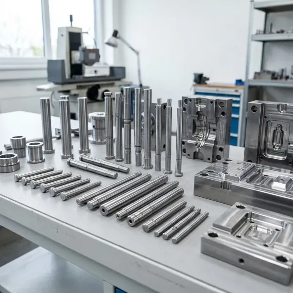
Send the package to a DFM-capable shop and ask for the tolerance review as part of the quote. At DieStrike, DFM feedback returns within 24 hours, and the review flags exactly the callouts covered here: undated profiles, chain tolerances, blanket tight title blocks and datum features that cannot be molded or measured repeatably. Fixing them before cutting steel is the cheapest engineering hour in the program.
FAQ: GD&T for Mold Buyers
Q1. What does datum A, B, C mean on a mold drawing?
It is a three-feature reference frame applied in order. A constrains three degrees of freedom, usually the parting-face plane. B constrains two more, typically a locating edge. C locks the last one, often a hole or pin feature. On the mold side, A maps to the parting surface, B to a cavity wall or slide interface and C to a core pin. All geometric callouts reference this frame, and the CMM rebuilds it before every measurement.
Q2. How tight can injection molded part tolerances realistically get?
Commercial precision sits at ±0.05 mm for most resins, precision work reaches ±0.02 mm, and ±0.01 mm or tighter is micro-molding territory that needs stabilized process, temperature-controlled metrology and select-fit inserts. The mold steel itself is machined tighter than the part demand, typically ±0.005 mm on critical mold dimensions and ±0.002 mm on component geometry, because shrinkage variation and process window consume the rest of the band.
Q3. What is bonus tolerance and why does MMC matter for molds?
Bonus tolerance is extra position allowance a feature earns as its actual size departs from MMC. A φ2 ±0.1 mm hole with position φ0.2 mm at MMC has a φ0.2 mm zone at φ1.9 mm but a φ0.4 mm zone at φ2.1 mm. For molds, that means core pins made at the LMC end can be placed with double the positional freedom while assembly risk stays unchanged, which relaxes plate machining and pin fits.
Q4. Does an undated profile callout cost more than a dated one?
Usually yes. A dated profile gives the mold shop a machining reference and the CMM a stable alignment, so measurement repeats within a few micrometres. An undated profile controls form only, forcing best-fit evaluation whose results drift 0.02 mm to 0.05 mm with probe strategy. Shops price that ambiguity as extra finishing hours and extra measurement passes, and buyers absorb the dispute risk at T1.
Q5. What GD&T information must an RFQ drawing contain for a firm mold quote?
At minimum: a complete A/B/C datum frame on moldable surfaces, geometric callouts with modifiers on every critical feature, a realistic title-block tolerance, Ra values by zone, resin grade with shrinkage data, and the expected first-article measurement level. Missing items force worst-case assumptions, typically adding 10% to 25% contingency to the quote.
The Bottom Line
GD&T callouts are cost decisions in drawing form. Dated profiles, correct modifiers and a two-tier tolerance scheme keep mold steel where it needs to be and nowhere tighter. Undated profiles, chain dimensions and blanket ±0.01 mm prints double machining classes and turn T1 into a measurement argument. Read the frame, question every modifier and agree on datum simulation before the RFQ goes out.
DieStrike is an IATF 16949 certified precision mold manufacturer with over 120 machines, holding ±0.005 mm mold accuracy and ±0.002 mm component geometry, with cavities heat treated to HRC 62 and DFM feedback inside 24 hours. Send us your print for a tolerance review before you commit tooling budget at contact us.
KEEP READING
Related Reading
How to Read a CMM Report: Dimensional Data for Mold Buyers
Nominal vs actual vs deviation, true position as a diameter, Cp/Cpk at 1.33 and 1.67, and the 23 ±1 °C measurement rules behind every CMM sheet.
Read articleArticleHow to Hold ±0.002mm: Precision Mold Tolerances
What it actually takes to hold ±0.002 mm on mold components: machine class, temperature control, steel stability and CMM verification order.
Read articleArticleHow to Write a Mold RFQ: 10 Fields That Get You Better Quotes
The 10 fields that separate a firm mold quote from a placeholder number, from steel and cavity count to tolerance class and validation docs.
Read articleServiceMold Design and DFM
24-hour DFM feedback on your part print: datum scheme, tolerance feasibility, shrinkage compensation and steel selection before cutting starts.
Read articleNEXT STEP
Ready to Start Your Mold?
Send us your element dimensions or part numbers — our team responds within 24 hours with pricing and lead time.

Written by
Ray ChanMold Buyer's Guide Author · Precision Mold Manufacturing Specialist. Ray helps global importers, distributors and OEMs source factory-direct molds and mold parts.