
Stripper Plate vs Ejector Pins: How to Choose an Ejection System
Table of Contents
Shot 14 of an 8-cavity polycarbonate housing mold ejected with a 0.3 mm dimple on the show face. The ejector pin under that spot carried a 1.5 mm tip against a 0.8 mm wall, and the part was still warm enough to deform. Cavity 5 repeated the defect every cycle, and the fix meant moving steel in the ejector plate, not changing a process setting.
That failure is why ejection method is a mold design decision, not a trial decision. Pins push at points. Stripper plates and rings push along an edge band or across a broad flat. The two methods live in different plate stacks, need different mold height, and leave different marks. You cannot swap one for the other after the tool is cut.
This guide compares ejector pin ejection against stripper plate and stripper ring ejection for mold buyers and tooling engineers. It covers how each mechanism works, the geometry where pins fail, the geometry where strippers win, hybrid layouts, mechanism anatomy, cost, and a decision matrix by part geometry. Values are typical industry practice and typical published material figures; verify each against your resin datasheet and a stress calculation before cutting steel.
The Snapshot
- Ejector pins apply force at point contacts that typically total only ~2-5% of projected part area for engineering resins. Verify with a stress calculation before relying on the rule.
- Thin walls of 0.5-1.0 mm are the classic pin failure zone. Pin tips can push through, dimple, or bend the wall before the part releases.
- A stripper plate or ring pushes the full perimeter edge band or a broad flat, so local pressure drops by an order of magnitude or more and no pin marks reach cosmetic faces.
- Glossy, mark-prone resins such as PC and PMMA show witness marks at depths below ~0.05 mm. Amorphous PC shrinks 0.5-0.7% and grips lightly; semicrystalline PP shrinks 1.5-2.5%, shrinks onto the core, and often needs more ejection force.
- Stripper ring inserts typically run hardened to HRC 58-62. Stripper travel equals the ejection stroke plus 3-5 mm clearance, and the mechanism adds mold height and cost over pin-only tooling.
- Choose pins for boss- and rib-rich parts with hidden push lands. Choose a stripper when walls are thin, faces are cosmetic, or release needs a full-perimeter breakaway.
Why the Ejection Method Is Decided at Mold Design, Not Trial
Ejection force is a geometry bill. It scales with the projected area of the part hugging the core, the draft on those surfaces, and how hard the resin shrinks onto the steel. A flat-bottomed deep box grips more than a shallow tray of the same footprint, because more side-wall area is in contact with the core.
Resin chemistry sets the grip, and the pattern is not intuitive. Amorphous PC shrinks about 0.5-0.7%, a typical published figure, and releases from the core early in cooling. Semicrystalline PP shrinks 1.5-2.5%, typical for unfilled grades, and pulls the part onto the core as it crystallizes. That shrinkage grip is why PP thin-wall containers often need more ejection force than a PC housing of similar size, even though PP feels softer at room temperature.
The ejection mechanism has to be chosen when the ejector plate, return pins, stripper hardware, and mold height are still numbers on a drawing. Pins need holes bored through the core and the ejector plate, with pin lands positioned on the part. A stripper needs a moving plate or ring, clearance around the core, guide and return pins, and typically tens of millimeters of extra stackup height. None of that is a trial-floor adjustment.
Changing method late means re-cutting plates, re-balancing ejection, and often re-qualifying the part surface. The discipline that keeps ejection cheap is the same one that keeps every other mold feature cheap: decide the mechanism in DFM, before moldability geometry rules are frozen. A 24-hour DFM review that flags "no push land under this cosmetic face" is cheaper than a plate re-cut in week 6.

Two questions settle most ejection debates early. First: does the part have a continuous non-show surface the ejection system can push on? Second: how thin and how cosmetic are the walls the push would cross? Answer those two and the mechanism usually picks itself.
How Ejector Pins Eject: Point Loads, Pin Marks, and Bending Risk
Ejector pins are hardened cylindrical rods that slide through the core and push the part off at the end of the cycle. They are standard catalog components in DIN and ISO sizes, with head styles, length options, and steel grades made for different duty. The tooling engineer places them under bosses, ribs, lands, and flat areas where the pin tip can push without damaging a show surface.
The physics is a point load. A pin tip of 1 to 3 mm diameter carries a share of the total ejection force. The sum of all pin tip areas on a typical engineering-resin tool lands near 2-5% of the projected part area. That rule of thumb is a starting point, not a license. At each tip, local pressure equals the total force divided by a small footprint. A modest total force can still exceed the yield strength of a warm, thin wall. Run the stress check on every thin section a pin touches.
Pin marks are the visible cost of that concentration. A pin that pushes hard enough leaves a witness mark, and on a gloss face even a mark below ~0.05 mm deep reads as a halo or a gloss change. Push a PC or PMMA part while it is still warm and the mark can also carry micro-stress whitening that survives polishing attempts. Surface finish of the pin tip, pin length, and fit all change how deep the mark goes. The root causes and fixes are covered in our ejector pin marks guide.
Pins also bend. A pin with a long unsupported length, pushed against a part that has not fully released, buckles or bows. Thin walls make the problem worse because the pin meets little resistance before it deforms the wall itself. That is why pin layout on 0.5-1.0 mm walls is a drawing discipline, never a "start small and add pins at trial" plan.
What pins do well is reach. They slide into bosses, stand behind ribs, and push exactly where the geometry offers solid material. Where a part is full of pushable internal features, pins eject it with the smallest tool and the lowest cost.
How a Stripper Plate or Ring Ejects: Perimeter Push With No Marks
A stripper plate is a moving plate that surrounds the core and pushes the part at its perimeter edge band, or across a broad flat face. It strips the part off the core like a piston ring stripping a cylinder. A stripper ring is the single-cavity version: an annular hardened insert around one core that does the same job for that one cavity.
The difference from pins is contact area. Pins concentrate the total ejection force on a few percent of the part area. The stripper spreads the same force over the whole edge band, which is typically many times wider than the combined pin footprints. Local pressure drops by an order of magnitude or more. Thin walls that would dimple under a pin tip survive a perimeter push because the load is distributed instead of concentrated.
Marks disappear from cosmetic faces because nothing touches them. The stripper pushes the underside edge band, the flange, or a hidden flat. The show face never sees an ejector component. For a glossy PC or PMMA housing, that single fact can be the whole reason to choose a stripper.
The stripper is not free of demands. It needs a continuous push surface: an edge band wide enough to take the load without crushing, or a flat land the plate face can be machined to match. It needs a clearance path, because the plate or ring opening slides over the core with a controlled fit. It needs extra mold height for the plate and its travel. And it needs every rib, boss, and undercut accounted for in the plate face, because a rib standing proud of the push surface must have a pocket, not a collision.

When the part releases, the stripper acts on the whole rim at once. That simultaneous release matters for geometry that would tear if one corner let go first. Full-perimeter breakaway is exactly what a stripper is built to do.
When Ejector Pins Fail: Thin Walls, Cosmetic Faces, and Deep-Draw Cups
Pins fail in three predictable geometry classes. Learn to see them in the part model, because each one is a re-cut if it surfaces at trial.
Thin walls of 0.5-1.0 mm are the first. A warm, 0.6 mm PC wall under a 2 mm pin tip has little material to spread the load. The result is push-through, a dimple, or local whitening, and it repeats every shot. No amount of process tuning fixes a pin tip that is punching a wall that is too thin to carry the point load.
Cosmetic Class-A faces are the second. An untextured show surface on an appliance housing or a consumer electronics cover tolerates no witness mark, no gloss halo, and no ejector scar. If the only available pin lands sit under a visible face, the pin layout is wrong by definition. The part needs its push moved to hidden geometry, or the mechanism needs to change.
Deep-draw cups and boxes are the third. Tall side walls grip the core across their full height, and the bottom wall is often the thinnest section in the part. Pins pushing the bottom from the cavity side meet the strongest grip right where the material is thinnest. The bottom dimples, the pin pokes through, or a long pin bows under the load. Cosmetic cups in PC, clear covers in PMMA, and thin-wall containers all live in this class.
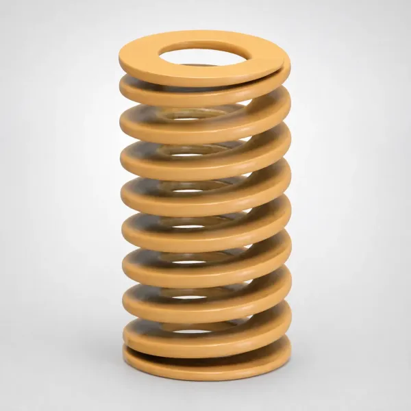
Material choice widens the failure zone. Glossy amorphous resins show pin marks early and visibly. Highly filled compounds can disturb the surface locally or bridge on a pin tip, leaving a print even when force is low. And a semicrystalline resin with high shrinkage multiplies the force a pin must carry, which converts a marginal pin layout into a bending or marking failure on day one.
When Stripper Ejection Wins: Thin-Wall Housings and Deep Boxes
Stripper ejection wins wherever the failure modes above are the alternatives. Thin-wall housings with cosmetic exterior faces are the cleanest case. The stripper pushes the underside edge band, so the show face never sees steel and the distributed load keeps a 0.6 mm wall from dimpling.
Containers, deep boxes, and cups follow the same logic at greater depth. The stripper ring strips the side walls off the core with a perimeter push, so the thin bottom never carries ejection force. Draft on the walls still matters, but the mechanism no longer depends on a thick bottom to survive.
Parts that need full-perimeter breakaway are stripper territory even when the wall is thicker. A rim that must release all at once, or a flange that would tear if one corner ejected first, points to a stripper. So does geometry with no internal pushable features.
Multi-cavity cosmetic parts also favor the stripper. Every cavity pushes through the same plate motion, so ejection is balanced across cavities by construction, and no cavity carries a pin pattern that marks its show face. The plate adds weight and machine stroke, but the per-cavity ring or plate face is uniform.

The stripper has one hard requirement: a push surface that exists and is wide enough. A part designed with no edge band, no flange, and only open-sided walls gives the stripper nothing to grab. That is why stripper decisions start in DFM, where a 1 to 2 mm continuous band can be added to the drawing instead of retrofitted to the steel.
When Ejector Pins Still Win: Bosses, Ribs, and Budget Limits
Pins remain the default for a large share of production tooling, and the reasons are geometry and money. A housing full of bosses, ribs, and internal lands offers dozens of hidden push points. Pins reach each one, carry a share of the load, and never touch a visible face. Adding a pin costs a drilled hole and a catalog part.
Parts with no cosmetic constraint are automatic pin territory. If the underside is hidden, the surface finish tolerance is loose, or the part is a functional bracket nobody inspects cosmetically, the witness-mark argument disappears. Pins eject that part at the lowest tool cost and the fastest build.
Open-sided geometry favors pins too. A part with no continuous perimeter band, interrupted rims, or slots that break the edge leaves a stripper plate nothing continuous to push. Pins tuck under whatever solid geometry exists.
Budget sensitivity is the last pin argument. A pin-only tool skips the plate machining, the hardened ring inserts, the extra guide and return pins, and the taller stack. On a high-volume, low-tolerance part, that saving is pure margin. Maintenance is simpler too: a worn pin is a standard part replaced in minutes, while a worn stripper ring is a fitted, hardened insert.
Here is the crisp version of the choice. Choose ejector pins when the part has bosses, ribs, or hidden lands to push on, and when those lands sit off every show face. Choose pins again when tool cost per cavity is a hard constraint. Choose a stripper plate or ring when walls run 0.5-1.0 mm or a cosmetic face must stay mark-free. Deep boxes, cups, and full-perimeter release needs also point to a stripper.
Hybrid Ejection: Stripper Ring and Ejector Pins Together
Many production parts are not pure cases, and hybrid ejection covers the middle. The standard hybrid is a stripper ring around the core that strips the perimeter while ejector pins push internal bosses and ribs through the middle of the ring. The ring handles the thin walls and the cosmetic rim; the pins handle the features the ring cannot reach.
The classic hybrid part is a thin-wall housing with internal mounting bosses. The ring strips the 0.7 mm walls with a distributed load, and short pins under the bosses push the features the ring would crush. Each mechanism does the work it is good at, and the failure modes of neither one reach the part.
Hybrids add engineering. The pins inside the ring must clear the ring's travel. That usually means an independent or sequenced ejector stage, extra return hardware, and careful timing so the ribs release before the walls bind. The extra stackup is why a hybrid tool runs as the most expensive of the three layouts, and why it should be justified by geometry, not habit.
Where a deep boss or rib needs annular push rather than a point, sleeves replace solid pins inside the hybrid layout. Sleeves ring the feature and push with a full annulus, which is the right tool when the boss itself is thin. The trade-offs between sleeves and solid pins carry over unchanged inside a hybrid stripper tool.
Stripper Mechanism Anatomy: Plate, Return Pins, and Hardened Ring
Build a stripper ejection system from five elements. The moving plate or ring carries the push face. Guide pins keep that plate square to the core through its whole travel. Return pins push the plate back before the mold closes. The ejector drive moves it forward each cycle. And on tools that push through a hardened wear zone, a stripper ring insert takes the duty.
The push face is machined to match the part. On a full plate, each cavity gets its own pocket, contour, and relief for ribs and bosses. On a single-core tool, an annular ring insert surrounds the core and its top face becomes the push band. That insert typically runs hardened to HRC 58-62, because it slides against the core and the part thousands of times per day. DieStrike builds these tools with hardened tool steel at HRC 62 on the wear faces.
The fit between ring bore and core is a controlled sliding clearance. Typical practice lands the clearance in the 0.02-0.05 mm class on the sliding diameter. It must be tight enough to keep flash out and loose enough to move freely at operating temperature. Thermal growth matters: a clearance set at 25 °C that ignores the hot cavity can bind at running temperature.
Travel rules follow the part, not the plate. Stripper travel equals the ejection stroke plus 3-5 mm of clearance, so the part clears the core completely before the next shot. The plate, its guide pins, and its travel add real height to the tool, typically tens of millimeters over a pin-only stack. The molding machine must have the stroke to cover it.
Return pins do the reset work. As the mold closes, the return pins push the stripper plate back to its home position against the spring or pull-back system, and guide pins hold alignment through the cycle. Worn alignment shows up fast on a stripper tool, as uneven wear on the ring, drag marks on the part, or premature flash.
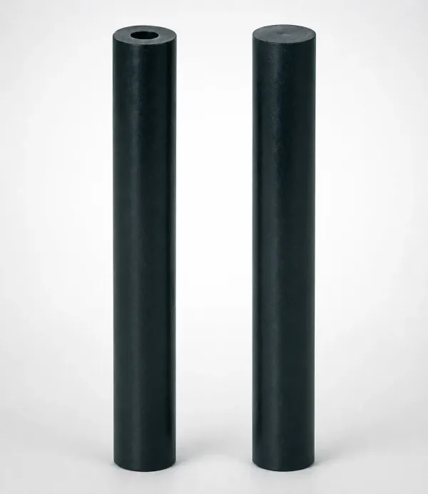
Maintenance on a stripper tool concentrates on the sliding interfaces. Keep the ring bore and the core OD clean, because debris between them gall the fit. Monitor ring edge condition, because a crushed or rounded edge on the push band shows up as part damage before it shows up as a tool failure. Standard stripper components and replacement inserts ship in 3 to 7 days at DieStrike for fast-track repairs.
Comparison, Cost, and the Decision Matrix
The comparison table below stacks the three layouts side by side on the attributes that decide ejection method: force distribution, marks, thin-wall behavior, and what each layout costs and wears.
| Attribute | Ejector Pins | Stripper Plate or Ring | Hybrid Ring Plus Pins |
|---|---|---|---|
| Force distribution | Point loads at pin tips, ~2-5% of projected area total | Full perimeter band or broad flat, spread load | Ring spreads the rim load; pins carry internal features |
| Surface marks | Witness marks and gloss change at every contact point | No pin marks on the pushed band when it is a non-show surface | Marks limited to hidden ribs pushed by pins |
| Thin-wall 0.5-1.0 mm suitability | Push-through, dimpling, and pin bending risk | Safe; load spreads along the edge band | Safe on walls; verify rib lands under pins |
| Deep bosses and ribs | Pins and sleeves reach them directly | Cannot push internal ribs; pockets required | Pins push ribs while the ring strips walls |
| Mold height added | None | Plate, return pins, and travel add stack height | Stripper stack plus independent pin stage |
| Relative tool cost | Baseline | Higher; plate machining plus hardened ring insert | Highest; two mechanisms and sequenced travel |
| Typical failure modes | Pin bend, pin break, mark defects | Ring galling, edge crush on narrow bands | Both of the above, plus timing mismatch |
← swipe to scroll →
Table: Typical practice comparison for mold-side ejection mechanisms. Contact-area percentages and clearances are industry rules of thumb; verify with stress and fit calculations for your geometry.
Cost follows the mechanism's moving mass. A pin-only tool is the cheapest to build: catalog pins, drilled bores, and a standard ejector plate. A stripper tool adds plate or ring machining, a hardened ring insert at HRC 58-62, guide and return pins, and a taller stack. That typically lands it at a meaningful premium over the pin-only tool of the same cavitation. The hybrid sits above both, because it carries the full stripper stack plus an independent pin stage.
The premium buys specific outcomes: no pin marks on cosmetic faces, thin walls that eject without push-through, and balanced full-perimeter release. When those outcomes prevent scrap, the premium pays for itself in the first production batches. When the part has no cosmetic constraint and walls are 1.5 mm or thicker, the premium buys nothing, and pins are the correct call.
| Part Geometry | First Choice | Why | Watch Out |
|---|---|---|---|
| Thin-wall cosmetic housing, 0.5-1.0 mm wall, Class-A face | Stripper plate or ring | Perimeter push avoids push-through and marks | Edge band must be wide enough to take the load |
| Deep-draw cup or box with thin base | Stripper ring | Strips side walls; the thin base never carries force | Confirm draft and ring clearance before steel |
| Housing rich in bosses and ribs, no cosmetic face | Ejector pins | Hidden features give solid push lands | Hold pin contact area near the 2-5% rule of thumb |
| Thin-wall housing with internal ribs | Hybrid ring plus pins | Ring strips walls, pins push hidden ribs | Sequence travel so ribs release before walls bind |
| Open-sided part with no perimeter band | Ejector pins | Nothing continuous exists for a plate to push | Add push lands or extra draft to compensate |
| Multi-cavity small cosmetic parts | Stripper ring per cavity | Balanced mark-free ejection across all cavities | Plate balance and per-cavity ring wear |
← swipe to scroll →
Table: Decision matrix by part geometry, based on typical mold-side practice. Use it as a shortlist, then confirm force, clearance, and cost with your mold maker.
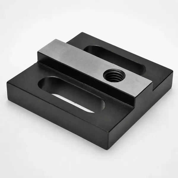
Run the matrix early. The worst ejection decisions are made after the part is frozen. Geometry that needs a stripper gets a pin layout, and the defect shows up in trial as marks or push-through. Move the mechanism decision to the DFM stage, where the part can still grow an edge band or a push land.
FAQ: Stripper Plate vs Ejector Pins
Q1. Can a stripper plate eject a part that has no edge band or flange?
Not usefully. The plate needs a continuous surface to push, so a part with only open-sided walls leaves the stripper nothing to act on. Either add a band in the part design, or use pins under whatever solid geometry exists. This is a DFM decision, made before the cavity is cut.
Q2. Does a stripper system eliminate all ejection marks?
It eliminates pin witness marks on the pushed surfaces, because no pins touch them. The stripper still must push a non-show surface: if the push band is itself a gloss face, the plate contact can leave its own drag or shear mark. Keep the push band off cosmetic surfaces and polish the plate face that contacts the part.
Q3. How much more does a stripper tool cost than a pin tool?
Framing varies by cavitation and geometry, but a stripper tool typically carries a meaningful premium over an equivalent pin-only tool. The premium covers plate or ring machining, a hardened ring insert at HRC 58-62, extra guide and return pins, and a taller stack. The hybrid sits above that. Ask your mold maker for the exact delta on your part during DFM, where the number is still free.
Q4. Why do return pins matter on a stripper tool?
Return pins push the stripper plate back to its home position as the mold closes, so the plate is fully reset before the next injection. Skipping or undersizing them lets the plate drift, which shows up as uneven ring wear, drag marks on parts, and eventually flash at the sliding fit.
Q5. Should the stripper ring have its own cooling?
Yes, in most production layouts. The ring sits against the cavity and runs at mold temperature, and its 0.02-0.05 mm sliding fit was set for that temperature. Thermal growth from an unmanaged ring can bind the fit or shift the push face. Route cooling near the ring and verify the fit at running temperature, not at the bench.
Q6. Does the resin decide the mechanism on its own?
No, but it sets the force budget. High-shrink semicrystalline resins such as PP at 1.5-2.5% grip the core harder and often need more ejection force, which favors spreading that force over more area. Low-shrink amorphous resins such as PC at 0.5-0.7% release more easily, but their gloss surfaces show pin marks sooner. Material and geometry together pick the mechanism.
The Bottom Line
Ejection method is a geometry contract written at mold design. Pins push at points and pay for that concentration with marks, dimples, and bending on thin walls. A stripper plate or ring pushes the perimeter and pays with plate machining, a hardened ring, and a taller mold.
Choose pins when bosses, ribs, and hidden lands carry the part off the core and no cosmetic face is at stake. Choose a stripper when walls run 0.5-1.0 mm or a Class-A face must stay mark-free. Deep boxes, cups, and full-perimeter release needs also point to a stripper. Choose a hybrid ring-plus-pin layout when thin walls and internal ribs exist in the same part.
Send the ejection question to DFM before the steel order. A mold maker that answers with force calculations, clearance checks, and a cost delta is a partner. One that answers with a pin pattern by default is selling you tomorrow's scrap. DieStrike reviews ejection layout as part of every DFM and builds under IATF 16949 across 120+ machines. Mold geometry holds to ±0.005 mm standard and ±0.002 mm precision, and molds ship in 2 to 5 weeks. Customers including TE Connectivity, Amphenol, and Luxshare run production on tools built to this discipline.
KEEP READING
Related Reading
Ejector Sleeve vs Ejector Pin: Which Ejection Method Fits Your Part?
Sleeves ring a boss or rib and push with an annular face instead of a point. Compare contact area, mark risk, and cost against solid pins for deep features.
Read articleArticleHow to Select Ejector Pins for Automotive Connector Molds
Small pins, tight grids, and zero-defect cosmetic rules. Diameter, steel, hardness, and layout guidance for automotive connector tooling.
Read articleArticleHow to Prevent Ejector Pin Marks: 5 Root Causes and Fixes
Pin marks trace to ejection force, layout area, fit, and process. Five root causes with the mold-side fix order, from pin polish to pack pressure.
Read articleServiceMold Design & DFM
Free 24-hour DFM feedback on your part drawing: manufacturability review, ejection layout, gate and runner design, steel selection, and quotation.
Read articleNEXT STEP
Ready to Start Your Mold?
Send us your element dimensions or part numbers — our team responds within 24 hours with pricing and lead time.

Written by
Ray ChanMold Buyer's Guide Author · Precision Mold Manufacturing Specialist. Ray helps global importers, distributors and OEMs source factory-direct molds and mold parts.