
How to Prevent Ejector Pin Marks: 5 Root Causes and Fixes
Table of Contents
You approved the connector housing mold in January. By March the customer's QC was holding every batch. A row of white crescents, one per ejector pin, showed on the B-side under raking light. Sorting cost 6 hours per lot. Scrap ran 9-12%. PPAP stalled while toolroom and molding argued about who changed what. That sequence is common enough to be boring, and it is almost never a mystery. Ejector pin marks are a mechanical contact defect. During ejection the pin presses the part surface with a local pressure higher than the material can absorb elastically. The surface then whitens, dimples, or cracks exactly where the pin touches. The root causes are five, checkable in an afternoon, and three of them are decided in mold design before the steel is cut. This guide covers the mechanism, the numbers that separate an acceptable witness mark from a reject, and the fixes in the order to try them.

The Snapshot
- Pin-tip bearing pressure is the number that matters. Keep it below the material's compressive yield: roughly 25-35 MPa for PP, 40-55 MPa for ABS, 60-75 MPa for PC. Above that, expect whitening on the first shot.
- Total ejector tip area should reach about 0.3-1% of the part's projected area on shallow parts, and more on deep ribs and bosses. Undersized layouts are the most common design-side cause.
- Pins must sit flush within ±0.02-0.05 mm of the cavity face. A pin standing 0.05 mm proud leaves a raised ring on every shot, and a pin 0.05 mm low leaves a dimple.
- Draft on cores: 0.5° minimum on polished steel, 1-2° on textured surfaces, paired with core polish at Ra 0.2-0.4 µm. Together they can cut ejection force by up to 50%.
Identifying Ejector Pin Marks: Symptoms and Types
Before you change anything, classify what you are looking at. The five defect families below have different root causes, and fixing the wrong one wastes a day of trials. Use raking light at about 30° across the surface, because ejector pin marks are shallow and invisible under direct lighting.
- White stress marks (blush). Frosty crescents or rings centered on each pin. The material yielded locally under the pin tip. Most common in PP, PE, and soft ABS grades.
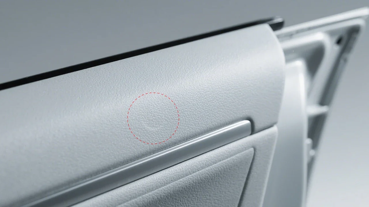
- Raised ring or dimple. A lip of 0.02-0.1 mm around the pin, or a depression at the pin tip. This is a geometry fault: the pin is proud of the surface, recessed, or the tip is too small for the load.
- Pin-side crack. A crack starting at the pin edge, usually on walls under 0.5 mm. Sharp pin edges, cold mold, or a pressure spike during ejection.
- Blush that grows over a run. Marks worsen after 50 or more shots. This points to blocked vents, pin wear, or clearance changes, not design.
Photograph the suspect surface at a fixed 30° light angle and fixed distance, and keep the images in the maintenance log. Shot-to-shot comparison is the fastest way to see whether a mark is stable, growing, or new. It also settles shift-to-shift arguments in seconds.
| Symptom | What It Looks Like | Most Likely Root Cause | First Check |
|---|---|---|---|
| White crescents at pin locations | Frosty ring, 1-3 mm around the pin, under raking light | Tip pressure above material yield | Bearing pressure: ejection force ÷ (pin count × tip area) |
| Raised ring around pin | Visible lip of 0.02-0.1 mm | Pin standing proud of cavity face | Height gauge or CMM, flush within ±0.02-0.05 mm |
| Dimple at pin tip | Local depression of 0.02-0.08 mm | Pin recessed, or tip too small for the load | Pin length and tip diameter vs mold drawing |
| Crack starting at pin edge | Fine crack on a wall under 0.5 mm thick | Brittle overload, sharp pin edge, cold mold | Break pin edges 0.05-0.1 mm radius; raise mold temp |
| Blush that worsens after shot 50 | Marks appear mid-run, absent at startup | Blocked vent, worn pin, clearance drift | Clean vents, check pin shank and clearance class |
← swipe to scroll →
Snap Check · True or False?
Ejector pin marks are mostly a packing-pressure problem — lower the pack pressure and they disappear.
True False
Answer: False. The number that matters is pin-tip bearing pressure, kept below the material's compressive yield (roughly 25-35 MPa for PP, 40-55 MPa for ABS, 60-75 MPa for PC). Undersized pin layouts are the most common design-side cause; packing is one of five root causes.
Root Cause 1: Ejection Force Exceeds Material Limits
Shrinkage grips the core. PP shrinks 1.5-2.5%, ABS 0.4-0.7%, PC 0.5-0.7%, and the part contracts onto the steel, generating contact pressure proportional to the modulus of the resin. Friction turns that grip into ejection force: F = μ × P × A. μ is the friction coefficient, typically 0.2-0.5. P is the contact pressure from shrinkage. A is the wrapped contact area. Deep ribs and bosses multiply A quickly. A 25 mm deep cup can double the ejection force of a flat part with the same footprint.
When total ejection force stays high, every pin works harder. The first sign is a stress mark on the pin carrying the most load. Attack the force itself before you attack the pins:
- Add draft. 0.5° minimum on polished cores, 1-2° on textured surfaces, 2-3° on cores deeper than 25 mm. For texture, add about 1° of draft for every 0.025 mm of texture depth.
- Polish along the pull direction. Core finish at Ra 0.2-0.4 µm (SPI B-2) drops the friction coefficient. Polishing with the draw direction instead of across it matters more than the Ra number. Cutting μ from 0.4 to 0.2 halves the ejection force.
- Vent the core roots. Add vents 0.02-0.05 mm deep and 3-5 mm wide at rib and boss roots. They break the vacuum suction that adds a spike to ejection force on every shot.
- Break vacuum on deep features. Cups deeper than 25 mm benefit from an air poppet that admits air before the ejector stroke, cutting suction force by up to 30%.
Go or no-go: after these changes, ejection tonnage on the machine readout should drop 20-50% at the same cycle settings. If it does not, the force is coming from somewhere else, and you move to Root Cause 2.
Root Cause 2: Pin Size and Layout Carry Too Little Area
Every ejector pin carries a share of the ejection force, and the pressure under each tip is the force divided by the tip area. Here is a worked example from a small housing that marked at every pin. Measured ejection force was 2,400 N. Layout A used 16 pins of 1.5 mm diameter. Total tip area was 16 × 1.77 = 28.3 mm², so bearing pressure was 2,400 ÷ 28.3 = 85 MPa. ABS yields near 45-60 MPa, so every pin marked the part. Layout B used 16 pins of 2.5 mm diameter, total area 78.5 mm², pressure 30.6 MPa, safely under the yield of PP and ABS. The fix was a rework of pin diameters, not a process change.
In a 16-cavity mold the same calculation repeats per cavity, and the cavities are not identical. If the mark shows only on cavities 4 and 11, measure those pins first: tip diameter, flushness, and shank straightness. Cavity-to-cavity variation in pin marks is almost always a pin geometry difference, not a process difference, because the process is common to all cavities. Record the cavity number on every inspection photo so the pattern becomes visible.
Thin-wall connector housings, the 0.35-0.6 mm wall parts common in automotive and consumer electronics, mark faster than any other geometry class. The wall is too thin for the stress to redistribute, so the pin contact stays local. If you design these parts, plan the ejector layout in the same session as the cooling layout. Never let a pin land on a wall thinner than 0.4 mm without a bearing-pressure check.
- Size for pressure, not for habit. As a starting point, total ejector tip area should equal 0.3-1% of the part's projected area, and more on parts full of ribs and bosses. Calculate bearing pressure for every pin and keep it under 70% of the material's compressive yield.
- Reserve small pins for ribs. Pins under 2 mm concentrate stress and bend under 30-50 kN loads. Use 1-1.5 mm pins only where a rib leaves no room, and count their area honestly.
- Change the ejector type where pins cannot win. Large flat faces take a stripper plate or stripper ring. Ribs take blade ejectors 1-2 mm wide. Undercuts take lifters. A stripper plate spreads the force over the whole face and makes bearing-pressure math almost irrelevant.
- Place pins symmetrically and near stiff features. Eject near ribs, bosses, and deep sections where shrinkage grip is strongest, and balance the layout so the plate does not rock. An off-center layout marks the part on the high side of the plate.
Quick audit rule: any pin tip above about 40 MPa on PP or 55 MPa on ABS means the layout is undersized and will mark. Recalculate after every pin diameter change.
Snap Check · True or False?
A pin standing 0.05 mm proud of the cavity face leaves a raised ring on every shot.
True False
Answer: True. Pins must sit flush within ±0.02-0.05 mm of the cavity face. At 0.05 mm proud you get a raised ring; at 0.05 mm low you get a dimple.
Root Cause 3: Pin Length, Fit, and Surface Finish
Pin geometry at the cavity face decides whether a mark is a witness line or a reject. A pin standing 0.05 mm proud of the cavity leaves a raised ring on every shot, because the pin face acts like a tiny stamp. A pin 0.05 mm low leaves a dimple that traps water in plating and reads as a defect on glossy parts.
- Set flush within ±0.02-0.05 mm. On cosmetic faces, set pins 0.00 to 0.02 mm low so nothing can stand proud. Verify every pin with a height gauge or a CMM; a CMM measures this to ±0.002 mm, which is the resolution this check deserves.
- Match the clearance class to the pin diameter. Standard ejector pin fits are DME M6, 0.008-0.013 mm clearance for pins up to about 6 mm, and M7, 0.013-0.025 mm above that. Tighter than M6 binds and galles, which shows up as streaks and uneven marks. Looser than about 0.03 mm produces pin flash, thin fins of plastic around each pin.
- Polish the tip, break the edge. Mirror tips at Ra 0.05-0.1 µm (SPI A-1) reduce the visible stress mark. A 0.05-0.1 mm radius on the tip edge stops the pin from cutting the part on retraction. Sharp edges leave crescent cracks on thin walls.
- Use pins that keep their geometry. Pins hardened to 58-62 HRC and nitrided keep tip flatness and shank straightness across long runs. A worn pin leaves marks that grow shot by shot. Inspect pins at 50,000-100,000 shot intervals and replace any with shank wear or tip rounding. DieStrike supplies precision ejector pins in HASCO, DME, and MISUMI-compatible styles with a 3-7 day standard lead time.
The fit audit is a 20-minute job: pull the ejector assembly, check every pin for flushness, straightness, and shank condition, and record the clearance classes. Most ring-mark complaints end here.
Replace pins in complete sets, not one at a time. A mixed set of new and worn pins spreads the ejection force unevenly. The worn pins mark exactly where the new pins stop carrying load. Lap the tip face flat after grinding, and record tip lengths in the maintenance log so drift becomes visible over time.
Root Cause 4: Ejector System Alignment and Binding
A healthy ejector system moves every pin the same distance at the same speed. When it does not, individual pins lead or lag, and the part gets uneven marks or bending loads. This is a maintenance fault, not a design fault, and it shows up mid-run after the mold has been through a few hundred thousand shots.
- Check pin straightness. Pins under 2 mm bend easily under repeated load. Straightness should hold within 0.01 mm per 100 mm of length. A bent pin marks the same spot on every shot and eventually scores its hole.
- Check plate parallelism. The ejector plate should stay parallel within 0.02 mm across its travel. A single off-center ejector rod rocks the plate, so the pins at the leading edge hit first. Add ejector guides or ball-cage guides when the plate rocks.
- Inspect return springs. Weak return springs let the ejector assembly crash back into the closed mold, denting pins and the part. Measure free length against the drawing and replace springs at 70% of rated cycle life.
- Watch for galling and scoring. Scratched pin shanks and galled holes mean the mold runs dry or the clearance class is too tight. Clean, relube with MoS2 grease, and ream or bushing oversized holes rather than pushing the pins back in.
- Check the ejection speed profile. Jerky, slam-start ejection adds dynamic load spikes that static calculations miss. Use a slow first 5-10 mm, then accelerate. The same mold that marks at 60 mm/s ejection is often clean at 30 mm/s.
If you find bent pins, follow our guide on replacing a broken ejector pin before touching any other variable. A single bent pin contaminates every trial you run after it.
Set a maintenance interval: visual pin inspection every 10,000 shots, full ejector system audit every 50,000-100,000 shots. The audit covers straightness, flushness, spring free length, and clearance class. Molds that skip this interval do not fail suddenly. They degrade one pin at a time, and the marks return slowly enough that nobody remembers when they started.
Root Cause 5: Packing, Temperature, and Cooling
When the mold design is sound and the ejector system is healthy, the last variable is the process window. Over-packing is the classic offender. High pack pressure and long hold time push more material into the cavity. The part grips the core harder, and the extra force lands on the pins.
- Reduce pack pressure 10-20%. Watch part weight as you step down. A 0.1% weight change is normal; a larger drop means you are leaving short shots and you should stop.
- Shorten hold time in 1 second steps. Hold time exists to feed shrinkage until the gate freezes. Once the gate is frozen, extra hold time only increases stress in the part.
- Raise mold temperature 10-20 °C. A warmer cavity keeps the skin softer at ejection, which reduces stress whitening. Budget the cycle time cost before you commit.
- Add 10-20% cooling time. Better-cooled parts carry less residual stress and release from the core more evenly. This is the slowest fix, but it is also the most reliable on thin-wall parts.
- Clean the vents. A blocked vent turns a clean mold into a vacuum pump, and the suction shows up as blush at the pins. Confirm vent depth of 0.02-0.05 mm and clear them at every scheduled maintenance.
- Use mold release only for the first 3-5 shots. After the initial break-in, stop spraying. Release buildup creates haze and separation lines that look like ejector defects and send you chasing the wrong root cause.
Run a small matrix before you call it: 30-50 shots sweeping pack pressure and mold temperature at two levels each. Inspect every 10th part under raking light. Record the shot count at which marks first appear. That record is what survives the handoff between shifts.
Fix Order and Verification
Work cheapest to most expensive, and verify at each step so you know what actually worked:
- Process first. Pack pressure, hold time, mold temperature, ejection speed. Cost is one shift and zero steel changes. If marks disappear, you are done.
- Recalculate the pin layout. Bearing pressure per pin against material yield. Add pins, enlarge diameters, or switch to a stripper plate.
- Audit pin geometry. Flush within ±0.02-0.05 mm, correct clearance class, polished tips with broken edges.
- Add draft and polish. 0.5-1° draft, Ra 0.2-0.4 µm core finish, vents at rib roots, air poppets on deep cups. This is a toolroom job and takes the longest.
- Rebuild the ejector system. Straighten or replace pins, fix plate parallelism, replace return springs, add guides.
| Fix | Typical Change | Expected Effect | Verify With |
|---|---|---|---|
| Reduce pack pressure | -10 to -20% | Lower grip force, marks fade | Part weight within ±0.1% |
| Enlarge pin diameter | 1.5 mm → 2.5 mm | Bearing pressure 85 → 31 MPa | Bearing-pressure calculation |
| Set pins flush | Within ±0.02-0.05 mm | Ring marks and dimples gone | Height gauge or CMM |
| Add draft and polish core | 0.5-1° plus Ra 0.2-0.4 µm | Ejection force down up to 50% | Ejection tonnage readout |
| Raise mold temperature | +10-20 °C | Less stress whitening | Visual check at 30° raking light |
← swipe to scroll →
Verification standard: run 50 shots, inspect parts at shot 10, 20, 30, 40, and 50 under 30° raking light. Zero whitening at every pin is the pass condition on cosmetic surfaces. Mark the cavity number and shot count on every inspected part. A mark that appears at shot 40 but not at shot 10 is a wear or vent problem, not a design problem. On non-cosmetic surfaces, a witness mark up to 0.05 mm raised or sunk may be accepted if the customer drawing allows it. Write the limit into the DFM agreement before the mold runs. Do not argue about it at PPAP.
On the design side, a 24-hour DFM review catches most of these issues before steel is cut. It checks pin layout, bearing pressure, draft, and venting. On the maintenance side, apply the same review to an existing mold with the pin geometry audit above. That is the fastest path to a clean surface on a mold that has been marking for months.
Frequently Asked Questions
What causes ejector pin marks on plastic parts?
Ejector pin marks appear when the pressure under a pin tip exceeds what the material can absorb elastically. The five root causes are excessive ejection force, undersized pin layout, wrong pin length or fit, and ejector system misalignment. Process settings such as over-packing or a cold mold add the fifth.
How do you fix ejector pin marks without modifying the mold?
Start with the process: reduce pack pressure 10-20%, shorten hold time in 1 second steps, and raise mold temperature 10-20 °C. Slow the ejection start and clean the vents. If marks persist after a 30-50 shot matrix, the cause is in the tool. Move to the pin layout and geometry fixes.
What is the acceptable ejector pin mark tolerance?
On cosmetic surfaces (SPI A-1 finish class), no mark should be visible under raking light. On non-cosmetic surfaces, a witness mark up to 0.05 mm raised or sunk is commonly accepted when the customer drawing allows it. Agree on the limit in the DFM phase, before tooling starts.
Ejector pin marks vs sink marks: how do you tell them apart?
Location and timing. Ejector pin marks sit exactly at pin positions, are crescent or ring shaped, and appear at ejection. Sink marks sit above thick sections or opposite ribs, are broad shallow depressions, and develop during cooling. A straightedge across the surface separates them in seconds.
How much draft angle prevents ejector pin marks?
Use 0.5° minimum on polished cores, 1-2° on textured surfaces, and 2-3° on cores deeper than 25 mm. Draft reduces ejection force but does not eliminate marks by itself, so pair it with adequate pin area and core polish at Ra 0.2-0.4 µm.
Can ejector pin marks crack thin walls?
Yes. On walls under 0.5 mm, especially in PP and ABS, a sharp pin edge under high bearing pressure acts as a stress concentrator. It can crack the part at ejection. Break the pin edge to a 0.05-0.1 mm radius, reduce bearing pressure, and raise mold temperature.
The Bottom Line
Ejector pin marks are a pressure problem. Keep pin-tip pressure below the material's yield. Keep pins flush within ±0.02-0.05 mm. Give the part enough draft. The marks then disappear before they cost a sorting shift. DieStrike builds IATF 16949-certified molds with ±0.005 mm standard machining accuracy and ±0.002 mm on critical features. Our HRC 62 ejector pins and 24-hour DFM review flag pin layout and ejection risk before steel is cut. Send us your part file for a mark-free first trial.
KEEP READING
Related Reading
7 Hot Runner Maintenance Checks Before Every Run
7 Hot Runner Maintenance Checks Before Every Run
Read articleArticle5 Mold Cooling Channel Design Tips for Faster Cycles
Mold maker's 5 cooling channel design rules: channel-to-cavity distance 2-2.
Read articleArticle5 Shrinkage Compensation Rules for Mold Design
Shrinkage compensation decides mold accuracy. Five rules: material rates from 0.3% to 2.
Read articleArticle5 Ways to Reduce Mold Cost Without Cutting Quality
Five proven ways to reduce injection mold cost without cutting quality: DFM before quoting, right-sized cavity count,…
Read articleNEXT STEP
Ready to Start Your Mold?
Send us your element dimensions or part numbers — our team responds within 24 hours with pricing and lead time.

Written by
Ray ChanMold Buyer's Guide Author · Precision Mold Manufacturing Specialist. Ray helps global importers, distributors and OEMs source factory-direct molds and mold parts.