
How to Replace a Broken Ejector Pin: 7 Steps
Table of Contents
A broken ejector pin stops a mold the same way a seized bearing stops a motor: fast, loud, and expensive. One 0.8 mm pin snaps at 3:40 AM on a 64-cavity connector mold, and the press alarm wakes a maintenance team that now owns a 400-piece sorting problem. The pin costs USD 4. The downtime costs USD 200 per hour. The scrap review costs a customer relationship.
Ejector pin failure is the most common mold repair call in any injection molding shop, and most teams replace the pin, not the problem. That is why the same mold comes back three weeks later with the same snapped shaft, the same galling marks, and a new production claim. A disciplined replacement sequence fixes the pin once: diagnose the failure mode, strip the mold, measure the bore, select the right steel, assemble with correct clearance, trial-run under load, and close the loop with spare stock. Each step has a measurable go/no-go criterion, and this guide gives you all seven.
The seven steps below assume the pin itself is the failed component and the mold is otherwise sound. That is true more often than not: on a 120+ machine tooling floor running connector, sensor, and EV housings, ejector pin failures are the number one reason a mold comes off the press outside a scheduled changeover. The difference between a 45-minute swap and a two-day ordeal is almost never the pin. It is whether anyone measured the bore before ordering.

The Snapshot
- DieStrike ejector pins ship in 3–7 days with MOQ 1, jig-ground to ±0.002 mm and mirror-polished to Ra 0.2, in HASCO / DME / MISUMI interchangeable dimensions.
- Standard ejector pin steel is SKD61 (H13 class) at 58–62 HRC; upgrade to SKH51 or add TiN coating for abrasive resins and high-cycle runs.
- Pin-to-bore clearance typically runs 0.005–0.015 mm depending on diameter; anything tighter promotes galling, anything looser produces flash.
- A correct replacement with documented measurements and a trial-run record keeps repeat ejector pin failure below 5% of mold repair events.
Step 1: Diagnose the Failure Mode
Do not order a replacement pin before you know why the old one died. A bent pin, a snapped tip, a galled shaft, and a worn land are four different failures with four different root causes. Replacing a galled pin with the same steel and the same clearance guarantees the same result.
Read the broken pin like a witness
Clean the pin and inspect it under 10–20× magnification. The fracture face tells the story. A bright, granular face with beach marks means fatigue, usually from a loose ejector plate or a spring that lost preload. A dull, torn face with necking means overload, usually from ejection force exceeding the column strength of the pin. Score lines running along the shaft with transferred steel mean galling against the bore wall.
Measure the straightness of the surviving shaft on a surface plate. A pin that bent more than 0.05 mm over its length was side-loaded, which points to an ejector plate misalignment, a tilted core, or insufficient draft on the part. None of these are fixed by a new pin.
Match the symptom to the root cause
| Failure | Visual signature | Typical root cause | Fix beyond the pin |
|---|---|---|---|
| Buckled shaft | Permanent bow, rub marks on one side | Column buckling under high ejection force | Larger diameter, stepped pin, or sleeve ejector |
| Snapped tip | Clean break at gate-side land | Overload, sharp corner, thin land | Radius the land, increase land length, add draft |
| Galling / seizure | Adhered steel, drag marks, stuck pin | Tight clearance, poor finish, no lubrication | Ream bore, polish to Ra 0.2, apply mold release |
| Land wear | Grooves, flash around pin hole | Abrasive resin, soft steel | TiN coating, SKH51 upgrade, replace bore liner |
← swipe to scroll →
Go/no-go: If the diagnosis points to the bore, the plate, the spring, or the part design, the replacement pin is only half the repair. Fix the driver first, then install the new pin.
Step 2: Strip the Mold and Document the Ejector System
Ejector pin replacement is a mold repair, not a part swap. You must open the mold safely, remove the ejector assembly, and record what you find before a single pin moves.
Safe strip sequence
Start with the press in manual mode, ejector system at home position, and the mold clamped. Remove the sprue picker or robot, disconnect the ejector rod, then separate the A and B halves on the bolster. Lay the B half face-down on clean wooden blocks so the ejector plate faces up. Remove the ejector rod clamp, the return pins, and the stop buttons before lifting the ejector plate assembly.
Keep the ejector plates stacked in the order they came off. Springs eject under preload, so compress and release them in a spring holder or vise before removal. Loose springs are a shop-floor injury, not a footnote.
Set the halves on dedicated mold blocks, never on the bare floor and never on a forklift pallet with protruding nails. A dropped B half scrapes the parting line and turns a one-pin repair into a full surface restoration. If the mold is hot, wait until the core and cavity reach 60°C or lower before you touch the ejector system; pulling pins from a hot mold draws heat-treated steel out of its hardness window and warps the bores.
Record the cycle count from the press controller before shutdown. It is the cheapest data point in the whole repair and the one that tells you whether the pin died at 8,000 cycles or 480,000. Wear life at 8,000 cycles is a design problem. Wear at 480,000 is a maintenance interval problem. The same pin, the same repair, two completely different actions.
Photograph and map every pin
Before pulling the pins, photograph the ejector plate layout and sketch a pin map: cavity number, pin number, diameter, length, head type, and land length. On a 64-cavity mold, identical-looking pins differ by 0.1 mm in length or 0.5 mm in head height. A pin map converts the mold repair from memory work into a checklist.
Tag the broken pin and its neighbors. Check the two pins beside the failure for early-stage galling or wear. Ejector pin failure rarely travels alone, and catching a second marginal pin during the same mold repair saves a second teardown in four weeks.
Inspect the supporting system
While the ejector assembly is out, check the return pins, the ejector guide pins, and the springs for wear or fatigue. Measure ejector plate parallelism with a dial indicator across the plate surface. More than 0.03 mm of deviation means the plate is loading pins unevenly, and every pin in that row will eventually fail. That measurement alone can turn a single pin repair into a full-ejector-system mold maintenance job, which is cheaper than three separate emergency repairs.
Step 3: Measure the Bore and Check the Tolerances
The bore the pin rides in decides whether the new pin lasts 10,000 cycles or 500,000. Measure it before you order anything.
What to measure and with what
| Feature | Instrument | Typical acceptance | Action if failed |
|---|---|---|---|
| Bore diameter | Bore gauge or pin gauge, 0.001 mm resolution | Pin diameter + 0.005–0.015 mm clearance | Ream to next step, use stepped pin |
| Bore ovality | Two-axis bore measurement | Within 0.005 mm of round | Ream or install liner bushing |
| Bore surface | Borescope or comparator | Ra 0.2–0.4, no scoring | Hone, polish, or line bore |
| Land length | Depth micrometer | Matches original drawing | Adjust land, radius edges |
| Plate pin-hole alignment | Concentricity gauge | Within 0.02 mm | Re-bush the plate hole |
← swipe to scroll →
Measure the bore at three depths: the gate-side land, mid-length, and the plate-side entry. Ejector bores wear first at the land, where pressure and abrasion concentrate. If the land end is 0.01 mm larger than the plate end, the bore is worn, not just dirty.
Decide: re-pin, ream, or re-bush
Three outcomes are possible. If the bore is round and within 0.005 mm of nominal, order a standard pin at nominal diameter. If the bore is worn past 0.01 mm oversize but still round, ream it to the next standard step and order a stepped or oversize pin. If the bore is scored, oval, or damaged by a broken pin fragment, install a liner bushing or have the hole line-bored, then order a pin matched to the reworked bore.
Never order a pin before this measurement is written down. The single most common ejector pin replacement mistake is ordering nominal diameter into a worn bore, which produces flash on shot one and a stuck pin by shot five hundred.
Record the measured values on the pin map itself: bore at land, bore at mid-length, bore at plate entry, ovality, and land depth. This one sheet becomes the inspection baseline for every future PM, so the next mold maintenance check has a number to compare against instead of a memory. If the mold has 32 or 64 cavities, measure a sample of six bores across the pattern and check the worst one. Cavity-to-cavity variation is a leading indicator of an imbalanced runner or a soft steel batch, and it shows up in the bores before it shows up in the parts.
Step 4: Select the Replacement Pin
With the bore measured and the failure mode diagnosed, the pin selection writes itself: material, hardness, coating, size, and head geometry.
Material and hardness
SKD61, the H13 class, is the workhorse ejector pin steel. It balances toughness against wear resistance and survives both the heat of the cavity and the shock of ejection. DieStrike standard ejector pins run SKD61 at 58–62 HRC, jig-ground to ±0.002 mm and finished to Ra 0.2 so the shaft runs clean without galling.
For abrasive compounds such as 30–40% glass-filled nylon or PBT, upgrade the material or the surface. Options in order of cost: TiN-coated SKD61 for moderate abrasion, SKH51 (high-speed steel) for severe wear, or a coated SKH51 pin for the worst cases. DieStrike offers TiN coating as a standard option, and the coating extends land life by 3–5× on glass-filled resins.
Size and geometry
Standard ejector pins cover 0.5–20 mm diameters in HASCO / DME / MISUMI interchangeable dimensions, so a replacement matches the existing head counterbore and bore without rework. Confirm four dimensions against the pin map: body diameter, overall length, head diameter, and head height. On stepped pins, also confirm the step diameter, step length, and the corner radius at the step, which is where stepped pins break if the corner is sharp.
If the diagnosis in Step 1 was buckling, do not order the same diameter. Either step up one standard size, order a stepped pin that thickens the unsupported mid-section, or switch to a sleeve ejector. A 1.0 mm pin with a 30:1 length-to-diameter ratio is a buckling accident waiting for a hot shift.
Ordering for speed
With MOQ 1 and a 3–7 day lead time, ordering one emergency pin is fast. Ordering every pin on the repair list in one purchase order is faster overall, and it builds the spare stock you need for Step 7. Send the pin map, the measured bores, and the failure photos with the order. A supplier that sees the diagnosis can flag a wrong material before it ships. Browse DieStrike ejector pins for standard, stepped, and blade options with the interchange tables.
Step 5: Assemble the New Pin
Assembly is where clean measurements meet dirty reality. Work on a clean bench, with the ejector plates on blocks, and verify the pin against the packing slip before installation.
Fit check before insertion
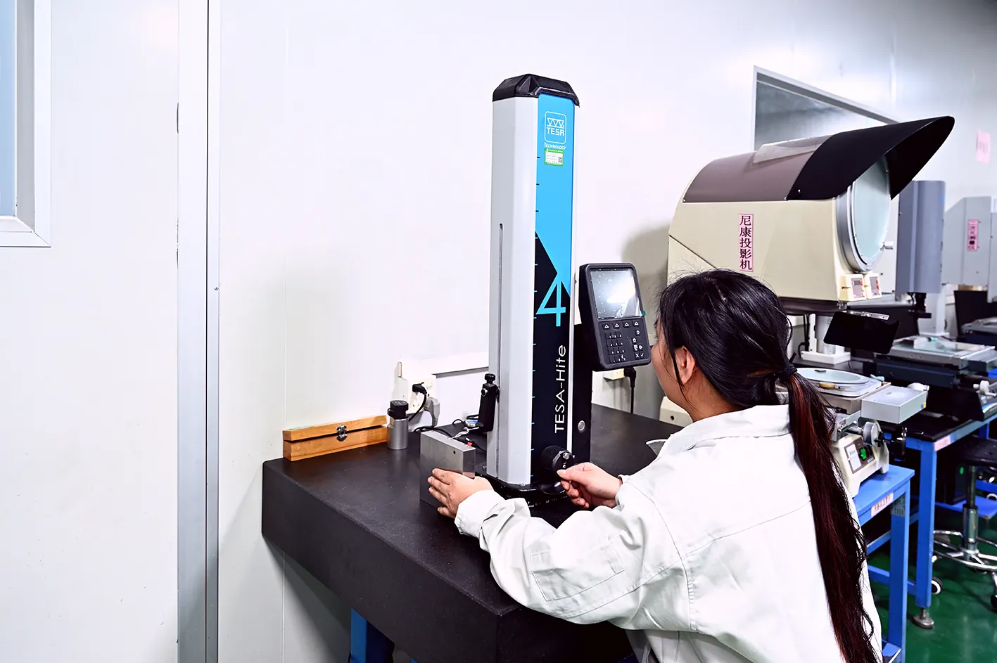
Verify the new pin diameter with a micrometer and the bore with a pin gauge, then test the fit by hand. The pin should slide through the bore with a smooth, uniform drag over the full stroke. It should not drop through under its own weight in a vertical bore, and it should never require force. Force at the first fit means clearance below the 0.005 mm floor, and that pin will gall within hours.
Check the head seat. The head must sit flush in the ejector plate counterbore with the head height matching the drawing to ±0.02 mm. A proud head rocks the ejector plate and bends the pin at the head, which recreates the buckling failure you just fixed.
Install and lubricate
Insert the pin from the cavity side or the plate side, whichever the design specifies, and seat the head. Apply a thin film of high-temperature mold grease to the shaft land before final seating. Do not flood the bore; excess grease migrates to the cavity and shows up as oil stains on parts. Reinstall the ejector plates, springs, return pins, and the ejector rod in reverse order, then hand-cycle the ejector system through the full stroke three times. The system should move freely with no binding at any point in the travel.
Torque and verify travel
Torque the ejector rod clamp and return pin fasteners to the mold maker's spec, not to feel. Check the total ejector stroke with a dial indicator against the press setting, and confirm the pins return flush with the cavity surface. Go/no-go: zero pins proud, zero pins recessed more than 0.02 mm, full free stroke, no audible click or bind.
Step 6: Trial-Run and Verify the Repair
A mold repair is not finished when the mold is closed. It is finished when the parts pass and the ejector system survives a loaded cycle.
Dry cycle first
Run the mold in manual mode with the press on slow. Watch the ejector stroke through the full cycle: forward, dwell, return. Confirm every pin moves with the plate, no pin sticks on the return, and no pin hangs past the cavity surface. Repeat for ten dry cycles before introducing material.
Short shots and a full shot
Take a short shot at 30% fill and inspect the cavity side. A sticking pin leaves a mark on the part face; a pin with too little land lets flash creep past the gate. Then run a full shot at normal parameters. Check the part for ejector marks, flash around the pin holes, and drag lines on the ribs where blade pins eject. Ejector marks deeper than 0.05 mm or flash over 0.03 mm around a pin are failures, not cosmetics.
Measure the parts
Check the first five parts on the critical dimensions that the failed pin affected. On connector housings, that is the terminal cavity pitch and depth. Use a CMM or optical comparator to confirm the dimensions hold within the customer tolerance band. Then run a 50-cycle soak at production speed and re-check the ejector system for heat, noise, and pin free-movement.
Document the results: stroke, temperatures, pin travel, part dimensions, and any adjustment. That record is the proof of repair for the production handover and the baseline for the next mold maintenance interval.
One more check before the mold leaves the bench: confirm the new pin's head height against the other pins in the same ejector plate row. On multi-cavity tools the ejector plate pushes all pins together, so a pin head that sits 0.05 mm higher than its neighbors takes a disproportionate share of the ejection load every single cycle. That is how a brand-new pin becomes the next failure in six weeks. Set the head height flush with the plate within 0.02 mm, and you have balanced the entire row.
Step 7: Prevent the Next Failure
The last step of a good ejector pin replacement is making sure you never need to do it as an emergency again.
Build spare stock by pin map
Every mold should have a spare kit: one pin per diameter and length in the pin map, plus the springs, return pins, and o-rings that wear with them. With MOQ 1 and 3–7 day standard delivery, a stocked spare kit turns a line-down event into a scheduled 45-minute repair. Stock the top 20% of pin sizes that cause 80% of your failures, which in most connector and automotive molds are the small diameters under 1.5 mm.
Schedule the inspection, not the failure
Add ejector pins to the mold maintenance checklist. Measure bore diameter at the land every 50,000 cycles on standard resins and every 20,000 cycles on glass-filled compounds. Inspect land wear, shaft straightness, and plate alignment at the same interval. Re-lubricate the ejector system at each PM, because dry pins gall and galled pins snap.
Log the root cause
Close the mold repair loop with a one-line root cause entry in the mold logbook: failure mode, measured bore, pin spec, and the fix. After three failures on the same cavity, the log tells you to stop buying pins and rework the ejector system. That is the difference between mold repair as firefighting and mold maintenance as engineering. If the mold needs deeper work, DieStrike's mold repair and maintenance service covers bore re-lining, surface restoration, and preventive maintenance programs.
The 7-Step Checklist
- Diagnose: inspect fracture face, shaft straightness, and side-load marks under magnification.
- Strip: safe sequence, spring control, pin map, and photos before disassembly.
- Measure: bore diameter at three depths, ovality, surface, land length, plate alignment.
- Select: SKD61 58–62 HRC standard; TiN or SKH51 for abrasive resins; stepped for buckling.
- Assemble: hand fit check, flush head, thin grease, full-stroke dry cycle.
- Verify: dry cycles, short shots, full shot, first-five part measurement, 50-cycle soak.
- Prevent: spare kit per pin map, PM inspection intervals, root cause log.
FAQ
How long does it take to replace an ejector pin?
A scheduled replacement with the spare pin in stock takes 30–60 minutes on a single mold. With a custom pin on order, add the 3–7 day manufacturing lead time. An emergency teardown with no spare and a worn bore takes a shift and a half, which is the strongest argument for the Step 7 spare kit.
What clearance should an ejector pin have in its bore?
Typically 0.005–0.015 mm diametral clearance depending on pin diameter, resin, and mold temperature. Small pins run at the tighter end, large pins at the looser end. Less clearance causes galling and sticking; more clearance causes flash and part flash lines.
Why does my ejector pin keep breaking in the same cavity?
Three failures in the same cavity mean the pin is not the problem. Check bore wear and ovality, ejector plate alignment, spring preload, and part draft at that cavity. If the cavity is at the end of the runner system, it may also be overpacked, which raises ejection force beyond the pin's column strength.
SKD61 or H13: which ejector pin steel is better?
SKD61 and H13 are the same steel family, with SKD61 being the JIS designation and H13 the AISI/SAE equivalent. Both run at 58–62 HRC for ejector pins. The material choice matters less than the coating: TiN-coated pins last 3–5× longer than uncoated on abrasive resins.
Can I straighten a bent ejector pin and reuse it?
No. Cold straightening leaves residual stress and micro-cracks that convert a bending failure into a snapping failure at a random cycle count. A straightened pin is a warranty claim waiting to ship. Replace it and fix the side-load that bent it.
The Bottom Line
Ejector pin replacement is a seven-step mold repair, not a part swap: diagnose the failure, strip and document the ejector system, measure the bore and tolerances, select the right steel and size, assemble with verified fit, trial-run under load, and build spare stock so the next failure is a scheduled job. Every step has a measurable gate, and skipping the measuring step is how repeat failures are manufactured.
When the repair needs a pin that matches the original geometry exactly, DieStrike delivers standard, stepped, and blade ejector pins in SKD61 at 58–62 HRC, ground to ±0.002 mm, in HASCO / DME / MISUMI interchangeable sizes, with MOQ 1 and 3–7 day lead times. Send us your pin list for a same-week delivery.
KEEP READING
Related Reading
5 Mold Cooling Channel Design Tips for Faster Cycles
Mold maker's 5 cooling channel design rules: channel-to-cavity distance 2-2.
Read articleArticle5 Shrinkage Compensation Rules for Mold Design
Shrinkage compensation decides mold accuracy. Five rules: material rates from 0.3% to 2.
Read articleArticle5 Ways to Reduce Mold Cost Without Cutting Quality
Five proven ways to reduce injection mold cost without cutting quality: DFM before quoting, right-sized cavity count,…
Read articleArticle7 Gate Design Best Practices for Balanced Filling
Mold maker's 7 gate design rules for balanced multi-cavity filling: gate depth 50-80% of wall thickness, land 0.5-1.
Read articleNEXT STEP
Ready to Start Your Mold?
Send us your element dimensions or part numbers — our team responds within 24 hours with pricing and lead time.

Written by
Ray ChanMold Buyer's Guide Author · Precision Mold Manufacturing Specialist. Ray helps global importers, distributors and OEMs source factory-direct molds and mold parts.