
7 Gate Design Best Practices for Balanced Filling
Table of Contents
A 32-cavity connector mold left the build floor with gates copied from a similar job, not from the drawing. Cavities 1-6 filled 0.4 s ahead of the pack, cavity 24 shorted at 97% of its volume, and 18,000 housings from the first 120,000-piece run went to scrap before the press stopped. The mold steel was fine. The gate design was not. Every cavity carried the wrong gate type, depth, or position for its material and wall section.

Gate design is the last mold-side decision made before steel is cut, and the first thing that shows up in the part. The gate sets the fill rate, the pressure drop, the shear heating, the weld line position, and the vestige the customer photographs. This article lists 7 practices that keep multi-cavity tools balanced, from gate type selection to gate insert replacement scheduling. Every practice carries a number you can verify at T1 sampling.
The Snapshot
- Gate depth starts at 50-80% of nominal wall thickness, with gate land held at 0.5-1.5 mm.
- Polycarbonate tolerates about 40,000-60,000 s⁻¹ at the gate, while PA66 runs 60,000-100,000 s⁻¹ (typical figures).
- Fill time spread across cavities should hold within 5%, and cavity weight spread within 0.5% on a balanced runner.
- A gate restriction adds 30-60% of the total system pressure drop in a cold runner mold (typical).
- Replaceable gate inserts turn erosion rework into a 30-60 minute swap per cavity.
Gate Design Failures: The Scrap Math
The gate is the final restriction between the runner and the cavity. It meters the melt, sets the flow front, and freezes first so the part can separate from the runner. When the gate is wrong, nothing downstream fixes it. The molding machine can change pressures and speeds, but a gate that is too small, too large, or misplaced prints its flaw on every cycle.
Costs are the honest measure. Reworking one gate by welding or inserting steel runs $300-$1,500 per cavity typical, plus 2-5 days of press downtime. A scrapped multi-cavity batch runs $10,000-$50,000 in material, labor, and missed delivery (industry figures). An unbalanced 32-cavity tool repeats that loss on every run until the gates are corrected.
Balance is a mold design property. It is decided when the runner layout, gate type, gate depth, and gate position are drawn, then verified at T1 sampling with part weights or cavity pressure sensors. DieStrike returns DFM feedback within 24 hours on gate placement and sizing, and gate selection advice with a cost breakdown within 48 hours.
Snap Check · True or False?
Any gate works as long as the cavity fills — gate type and depth are cosmetic.
True False
Answer: False. The gate sets fill rate, pressure drop, shear heating, weld line position, and the vestige the customer photographs. The 32-cavity case scrapped 18,000 housings because gates were copied instead of designed.
Practice 1: Match the Gate Type to the Geometry
Eight gate families cover nearly every production mold: edge, fan, tab, submarine, pin point, film, ring, and hot sprue tip. Each has a fill behavior, a vestige, and a cost profile. The mold maker picks the family from the part geometry, the material, the cavity count, and the cosmetic class of the surface.
Edge, Fan, and Tab Gates
An edge gate is a rectangular slot machined into the parting line on the side of the part. It suits flat walls, is simple to cut, and costs the least of any family. Depth runs 50-80% of the wall and width runs 2-4 times the depth. The vestige sits on a part edge and is trimmed flush in secondary work.
A fan gate widens from the runner to the cavity so the melt spreads over a band instead of a point. Use it on wide flat parts and thin walls where an edge gate would jet. The fan typically spans 60-80% of the part edge. The vestige is wider and must be machined off, so fan gates cost more to finish.
A tab gate feeds a small pad beside the part instead of the part wall itself. The melt enters the tab and then the part, which protects thin edges from jetting and helps hesitation on long thin parts. The tab is trimmed after molding. Tab gates are common on flat covers and thin-walled housings.
Submarine and Pin Point Gates
A submarine gate is a tunnel bored under the parting line that opens on the side wall of the part. The part is ejected against the runner, and the gate shears off automatically, so no trimming labor exists. Gate diameter runs 0.5-1.2 mm typical for small parts. The vestige is a small dot that can be placed on a hidden wall.
A pin point gate feeds from a three-plate mold through a small orifice onto the top face. Vestige diameter runs 0.3-1.0 mm and degates automatically at ejection. The three-plate stack adds 15-25% to mold cost typical, but it allows a gate on the cosmetic face with a small, grindable dot.
Film, Ring, and Hot Sprue Gates
A film gate is a full-width slot across one edge of a large flat panel. It produces a straight, even flow front and suits flat parts that must stay flat. The vestige runs the full edge and is machined off, so it is a finishing-cost decision.
A ring gate wraps around a circular part, like a gear or bearing housing, and fills radially from all sides. It eliminates weld lines on round parts. Vestige removal requires machining the inner ring, so it is chosen where fill behavior matters more than gate removal cost.
Hot sprue tips and valve gates feed melt directly into the cavity with no cold runner. A valve gate pin closes the orifice, leaving a vestige of 0.05 mm or less. Hot runner systems add the largest up-front cost, typically $5,000-$30,000 per mold depending on cavity count, and pay back on runner scrap and cycle time (industry figures). Our hot runner systems cover valve gates and thermal tips for multi-cavity work.
| Gate Type | Best Material Fit | Cavity Count Fit | Vestige | Relative Cost |
|---|---|---|---|---|
| Edge | ABS, PC, PP, unfilled resins | 1-8 cavities | Trimmed flush, 0-0.3 mm | Low |
| Fan | Wide flat parts, thin walls | 1-4 cavities | Wide band, machined off | Moderate |
| Tab | Thin edges, jetting risk | 1-8 cavities | Tab trimmed in secondary work | Low |
| Submarine | PP, PE, PA, auto-degating | 8-64 cavities | Dot 0.3-0.8 mm, automatic | Low |
| Pin point | Cosmetic tops, 3-plate molds | 4-32 cavities | Dot 0.3-1.0 mm, automatic | Moderate |
| Film | Large flat panels | 1-2 cavities | Full edge, machined off | Moderate |
| Ring | Gears, bearing housings | 1-4 cavities | Inner ring, machined off | Moderate |
| Hot sprue / valve | Cosmetic, glass-filled, high cavitation | 8-64 cavities | 0.05 mm or less with valve pin | High |
← swipe to scroll →
Table: typical industry figures; verify against your program.
Practice 2: Size the Gate From Wall Thickness
Gate depth is anchored to the nominal wall, not to the part volume. The standard range is 50-80% of wall thickness (typical). Unfilled amorphous resins like ABS and PC start at 50-60%. Semi-crystalline resins like PA66 and POM start at 60-80%. Glass-filled grades start at 60% and are verified by shear rate, because filler raises viscosity and erosion.
Gate width follows depth. For edge gates, width runs 2-4 times the depth. For fan gates, the fan spreads to 60-80% of the part edge. Gate land length, the straight channel between runner and cavity, holds at 0.5-1.5 mm. A land under 0.5 mm erodes quickly and is hard to cut. A land over 1.5 mm adds pressure drop and shear residence time.
Worked Example: 2.0 mm ABS Housing
Take an ABS housing with a 2.0 mm nominal wall and a 3.0 cm³ cavity volume. Start the edge gate at 60% of wall. Gate depth t = 0.6 × 2.0 = 1.2 mm. Gate width W = 3 × t = 3.6 mm. Land L = 1.0 mm. Gate cross section A = 1.2 × 3.6 = 4.32 mm².
Check the shear rate at the gate. Fill the cavity in 0.8 s, so volumetric flow Q = 3.0 cm³ / 0.8 s = 3,750 mm³/s. For a rectangular gate, shear rate = 6Q / (W × t²). That gives 6 × 3,750 / (3.6 × 1.44) = 22,500 / 5.18 = 4,340 s⁻¹. The ABS ceiling is 30,000-50,000 s⁻¹ typical, so this gate is safe by a wide margin.
Now repeat for a 0.9 mm gate depth. t = 0.9 mm, W = 2.7 mm, and A = 2.43 mm². Shear rate = 6 × 3,750 / (2.7 × 0.81) = 22,500 / 2.19 = 10,300 s⁻¹. Still safe, but pressure drop climbs because the restriction is smaller. Gate pressure drop scales with the cube of the depth, so the 0.9 mm gate carries about 2.4 times the pressure drop of the 1.2 mm gate.

Keep the gate pressure drop within 5-10 MPa for unfilled resins (typical). If the mold flow report shows more, widen the gate 10-15% or extend the fill time, never both at once. Record the final gate dimensions on the mold drawing so maintenance can verify them later.
Practice 3: Balance the Runner for Multi-Cavity Fill
Multi-cavity balance starts with the runner, not the gate. In a geometrically balanced layout every cavity sees the same runner path length, the same number of turns, and the same pressure drop. In an artificially balanced layout the runner diameters are varied to force equal pressure drop across unequal paths. Natural balance is preferred where cavity count and mold footprint allow it.
Runner diameter sets the pressure drop before the gate. For a small part with a 1-2 g shot, a main runner of 4-6 mm and secondary runners of 3-5 mm are typical starting points. Pressure drop in a runner scales with length and flow rate and with the fourth power of the radius, so a 1 mm reduction in a 4 mm runner raises resistance sharply.
Balance is measured, not assumed. At T1 sampling, weigh parts from every cavity. A balanced tool holds cavity weight spread within 0.3-0.5%. An unbalanced tool shows 1-2% or more, and the light cavities short first when the process window shrinks. Fill time spread across cavities should hold within 5% (typical practice).

Cold runner molds carry a second cost: runner scrap. The runner can be 20-50% of the shot weight on small parts (typical). Hot runners eliminate the cold runner, hold each cavity at its own temperature, and open the door to higher cavity counts. The trade-off is covered in our comparison of hot runner versus cold runner molds.
Shear heating in the runner changes the balance. Melt viscosity drops 10-20% for every 10°C rise, so a hot runner leg fills easier than a cold one. That is why the same mold can balance at one temperature profile and drift at another. Keep the runner temperature strategy fixed during T1 trials, then document it in the mold book.
Practice 4: Position the Gate for Weld Lines and Flow
Gate position sets the flow path, and the flow path sets the weld lines. Every time two flow fronts meet, a weld line forms. On glass-filled resins a weld line carries only 40-60% of the bulk strength (typical). The gate should place weld lines at low-stress locations, or merge the fronts so they knit instead of weld.
Flow front meeting angle decides the joint class. Fronts that meet at more than 135° knit together with near-full strength. Fronts that meet at less than 135° form a weak weld line. Gate position and the part geometry control that angle, so the mold maker sets the weld line quality at design time, not at the press.
Gate placement also controls the flow length. The ratio of flow length to wall thickness, L/t, should stay under 100-150 for unfilled resins and under 60-80 for glass-filled grades (typical). A gate near the thickest wall shortens the worst flow path and supports packing. Packing pressure reaches the gate region first, so gate the side of the part that needs the most pressure.
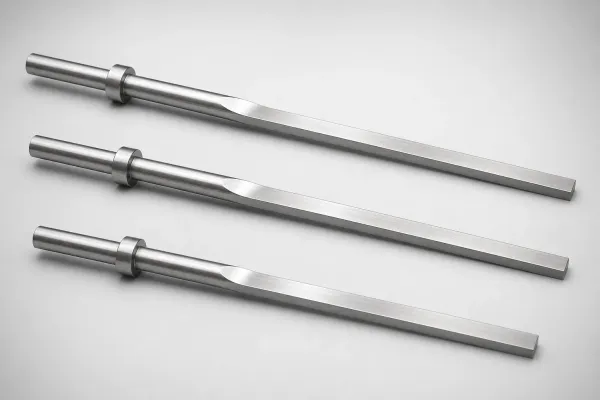
Jetting is a gate position defect. When melt exits the gate and travels across an open cavity before the front attaches to a wall, it cools into a worm-like mark. Aim the gate at an opposing wall or rib, use a tab gate, or cut the gate depth to 50% of wall to kill jetting.
Weld lines trap air at the last fill point. Add vents 0.02-0.03 mm deep at every weld line location so the trapped air escapes instead of burning. Vent placement follows gate position, which is why the vent plan is drawn with the gate plan.
Practice 5: Control the Vestige and Degating Force
The vestige is the gate remnant left on the part. Cosmetic class A surfaces allow 0-0.05 mm of vestige, general surfaces allow 0.1-0.3 mm, and submarine dots run 0.3-0.8 mm typical. The mold design must state which class applies before the gate family is chosen, because the family decides the vestige.
Edge gates are trimmed flush with a flush cutter, then stoned or hand-finished. Trimming adds 5-15 seconds of labor per part typical. Submarine, pin point, and valve gates degate automatically, removing that labor but leaving a dot. Valve gates cut the vestige to 0.05 mm or less and are the standard answer for painted cosmetic parts.
Degating force is a mold design number. A submarine gate with a 0.5-1.0 mm diameter shears at roughly 200-1,000 N per gate (typical). The ejector system must carry the sum of every gate plus the part ejection force. If the ejector is sized for the part alone, the gate shears late, the runner sticks, or the part distorts at the gate.
Brittle resins change the rules. PC and PMMA crack or whiten at a small gate when the part is ejected against it. For these resins, enlarge the gate, add a gate pad, or switch to a valve gate. The vestige target and the material toughness are set together at mold design.
Gate pullers belong on the runner. A sprue puller and gate puller hold the runner on the ejector side so the runner comes off the cavity cleanly. A runner that sticks adds 1-3 seconds to the cycle and risks a crushed mold face on the next close.
Practice 6: Stay Inside Material Shear Rate Limits
Shear rate at the gate is the fastest flow velocity gradient in the mold. It is calculated for a rectangular gate as 6Q / (W × t²), and for a round orifice as 4Q / (π × r³). Every resin family has a ceiling above which the melt degrades, molecular chains break, and the part shows splay, burn marks, or black specks.
Polycarbonate tolerates about 40,000-60,000 s⁻¹ at the gate (typical published range). PA66 runs 60,000-100,000 s⁻¹. PP and POM run near 50,000-100,000 s⁻¹. ABS holds 30,000-50,000 s⁻¹. PMMA is the tightest at 30,000-40,000 s⁻¹. These are gate design ceilings, not process recommendations, and they belong on the mold drawing.
Shear heating follows the shear rate. Melt temperature can rise 10-30°C across the gate (typical). For heat-sensitive resins like POM, the rise degrades the material even when the machine barrel is correct. A larger gate, a shorter land, or a slower fill rate drops the shear peak.
The land length sets how long the melt lives at high shear. Keep the land at 0.5-1.5 mm so the melt passes the restriction quickly. A long land from a worn or recut gate raises residence time and turns a balanced mold into a streak factory.
| Material | Max Shear Rate at Gate (s⁻¹) | Gate Depth Start (% of Wall) | Notes |
|---|---|---|---|
| PC | 40,000-60,000 | 50-60 | Brittle, use larger gate or valve gate |
| ABS | 30,000-50,000 | 50-60 | Standard edge gate sizing |
| PA66 | 60,000-100,000 | 60-80 | High viscosity, erosive when glass filled |
| POM | 50,000-100,000 | 60-80 | Heat sensitive, keep land at 0.5-1.0 mm |
| PP | 50,000-100,000 | 60-80 | Forgiving, submarine gate friendly |
| PMMA | 30,000-40,000 | 50-60 | Tightest ceiling, avoid small gates |
← swipe to scroll →
Table: typical industry figures; verify against your program.
Snap Check · True or False?
Exceeding the material's shear rate limit at the gate degrades the resin and can burn the gate.
True False
Answer: True. The gate is the highest-shear point in the tool, which is why gate size and land are engineered rather than copied — a degraded, overheated slug at the gate shows up on every shot.
Practice 7: Design for Gate Wear and Insert Replacement
Gates wear, and the wear changes the balance. Glass-filled resins are the fast case: a 30% GF PA66 can enlarge a gate orifice by 0.05-0.2 mm over 100k-500k cycles typical. The gate opens, the cavity fills faster, and the part weight drifts. One worn gate in a 16-cavity mold unbalances the whole tool.
Erosion has two drivers: abrasive filler and corrosive vent gas. The fix is material, not geometry. Gate inserts in H13 or SKD61 at HRC 52-58 hold up for unfilled resins. Tungsten carbide inserts are the standard answer for glass-filled and mineral-filled runs. Carbide gates cost more, typically 2-4 times a steel insert, and last 3-10 times longer (industry figures).
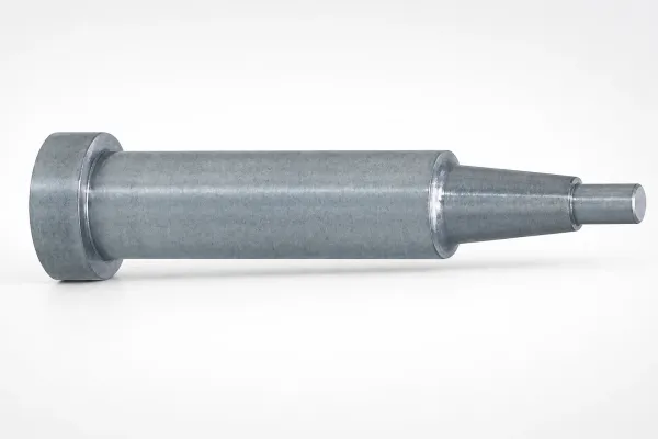
Replaceable gate inserts make wear a maintenance event, not a rebuild. A gate insert swap takes 30-60 minutes per cavity with the mold on the bench. A welded and recut gate takes 2-5 days. Design the gate pocket for an insert from the start, and the tool never goes back to the welding bench for a gate.
Schedule the inspection. Measure the gate orifice with pin gauges every 50k-100k cycles. Record the fill time spread at the same interval. When the spread passes 5%, or the part weight drift passes 1%, inspect the gates before touching the process. The sprue bushing wears the same way, and our sprue bushings and gates ship as standard parts in 3-7 days, so a scheduled swap never waits.
DieStrike builds under IATF 16949 across 120+ machines, holds mold size precision to ±0.005 mm and part geometry to ±0.002 mm, and hardens cavity inserts to HRC 62. Gate inserts are treated as consumable tooling, documented in the mold book with an orifice measurement baseline from T1.
Summary: The 7-Point Gate Design Checklist
Seven numbers cover the gate design. One, pick the gate family from geometry and cosmetic class. Two, set depth at 50-80% of wall. Three, hold the land at 0.5-1.5 mm. Four, balance the runner so cavity weight spread stays under 0.5%. Five, place the gate so weld lines sit in low-stress zones and L/t stays under 100-150. Six, verify shear rate against the material ceiling. Seven, schedule gate insert inspection every 50k-100k cycles.
Each number has a measurement. Depth is measured on the insert with a micrometer or pin gauge. Balance is weighed at T1, cavity by cavity. Shear rate is calculated from fill time and gate dimensions. Wear is measured with pin gauges against the T1 baseline. A mold book with those four baselines turns gate maintenance from a guess into a schedule.
The 2-4 week injection mold lead time at DieStrike includes the gate design review. DFM feedback arrives within 24 hours, and gate selection advice with a cost breakdown within 48 hours. That is the window where gate mistakes are still free to fix, before steel is cut.
FAQ: Gate Design for Balanced Filling
Q1. What gate depth should I use for a 2.5 mm wall?
Start at 50-80% of the wall, so 1.25-2.0 mm. Unfilled amorphous resins like ABS and PC start at 50-60%, or 1.25-1.5 mm. Semi-crystalline resins start at 60-80%, or 1.5-2.0 mm. Verify with the shear rate check at T1.
Q2. Which gate type leaves the smallest vestige?
A valve gate leaves 0.05 mm or less and is the standard for painted cosmetic parts. Pin point gates leave a 0.3-1.0 mm dot, and submarine gates leave a 0.3-0.8 mm dot on the side wall. Edge gates are trimmed flush in secondary work.
Q3. What shear rate can polycarbonate handle at the gate?
About 40,000-60,000 s⁻¹ typical. Above that ceiling, PC degrades, shows splay, and can crack at the gate. A larger gate or a longer fill time drops the shear peak.
Q4. How do I balance filling across 32 cavities?
Use a geometrically balanced runner with equal path length to every cavity, hold gate depth within 0.05 mm cavity to cavity, and verify by weighing parts from every cavity at T1. Target cavity weight spread under 0.5% and fill time spread within 5%.
Q5. How often should gate inserts be inspected?
Every 50k-100k cycles with pin gauges. Glass-filled resins shorten the interval to the low end. Replace the insert when the orifice grows 0.05-0.2 mm or the fill time spread passes 5%.
The Bottom Line
Gate mistakes scrap multi-cavity runs, and they are the cheapest errors to fix at design time. Type, depth, land, balance, position, shear rate, and wear schedule cover the gate design. Each has a number, and each number is verified at T1. The mold, not the press, decides whether the fill is balanced.
Send us your part drawing for DFM feedback within 24 hours, or get gate selection advice with a cost breakdown within 48 hours.
KEEP READING
Related Reading
5 Mold Cooling Channel Design Tips for Faster Cycles
Mold maker's 5 cooling channel design rules: channel-to-cavity distance 2-2.
Read articleArticle5 Shrinkage Compensation Rules for Mold Design
Shrinkage compensation decides mold accuracy. Five rules: material rates from 0.3% to 2.
Read articleArticle5 Ways to Reduce Mold Cost Without Cutting Quality
Five proven ways to reduce injection mold cost without cutting quality: DFM before quoting, right-sized cavity count,…
Read articleArticle7 Signs Your Mold Base Needs Replacement
A guide pillar with 0.04 mm play can scrap a 32-cavity run in one shift.
Read articleNEXT STEP
Ready to Start Your Mold?
Send us your element dimensions or part numbers — our team responds within 24 hours with pricing and lead time.

Written by
Ray ChanMold Buyer's Guide Author · Precision Mold Manufacturing Specialist. Ray helps global importers, distributors and OEMs source factory-direct molds and mold parts.