
5 Shrinkage Compensation Rules for Mold Design
Table of Contents
A single wrong number can scrap a $50,000 mold. Cut a cavity to the nominal part dimension without shrinkage compensation and the parts come out undersized by the full shrinkage rate. On a 100 mm POM dimension at 2.0% shrinkage, that is 2.0 mm of error. No tolerance band accepts that, and no polishing pass fixes it.
Shrinkage compensation is the mold design step that converts a part drawing into a cavity model that actually produces that drawing. The allowance is not one percentage. It is a set of corrections for material, geometry, gating, steel temperature and measurement, and it typically lands between 0.3% and 2.5% of the part dimension. DieStrike reviews this set on every quote, because the compensation error is the most expensive error a mold can carry.
This guide covers the five rules DieStrike applies to every injection mold, from a 2-week connector tool to a multi-cavity housing mold. Each rule comes with the numbers that matter, a reference table for common materials, and a worked cavity calculation you can reuse on your own parts.
The Snapshot
- POM shrinks 1.8-2.2%, PP 1.5-2.5%, ABS 0.4-0.7%, PBT+30% GF 0.3-0.8%. A single global rate misses every material.
- Flow and transverse shrinkage differ by up to 0.4-0.5% on crystalline grades, equal to 0.4-0.5 mm on a 100 mm part.
- Tool steel expands 11-12 µm/m·K, so a 150 mm cavity at 80°C grows 0.10-0.11 mm over its 20°C machined size.
- Trial-shot correction loops, driven by CMM measurement, close precision dimensions in one to three iterations.
- DieStrike machines compensated cavities to ±0.005 mm and verifies geometry at ±0.002 mm, with cavities hardened to HRC 62.
Rule 1: Use Material-Specific Shrinkage Rates
Shrinkage is the difference between the cavity dimension at room temperature and the cooled part dimension. It is expressed as a percentage of the nominal dimension. A 100 mm cavity in a 2.0% shrink material delivers a 98.0 mm part. The cavity must be cut larger, and that enlargement is the compensation allowance.
Every resin family has its own range, and the spread is wide. Crystalline materials shrink more than amorphous ones, because polymer chains pack into ordered lamellae during cooling. A 100 mm PP part can lose 1.5 to 2.5 mm, while an ABS part of the same size loses 0.4 to 0.7 mm. That packing is directional, so crystalline shrinkage depends on flow direction. Glass fibers add another layer, since fibers align with the melt flow and restrain shrinkage along that axis.
The direction split matters more than the average. On a 100 mm part in unfilled POM, flow-direction shrinkage can sit near 1.8% while transverse shrinkage runs to 2.2%. The 0.4% delta is 0.40 mm of cavity difference on one dimension. A mold built to a single average rate misses one axis by 0.2 mm, which is 10 to 20 times the ±0.005 mm cavity precision DieStrike machines to.
The cavity model, not the mold base, carries the compensation. DieStrike builds the allowance into the 3D cavity surface before programming the CNC toolpaths. The finished steel is then checked against the compensated model at ±0.005 mm, not against the part drawing.
Reference Shrinkage Rates for Common Molding Materials
Published datasheet values are starting points, not final numbers. They are measured on a standard test plaque with a defined wall thickness and flow length. Typical plaques use a 3.2 mm wall, which rarely matches your part. Your part geometry and gate layout shift the real value. Use the table below as the first-pass model, then refine it with the mold trial.
| Material | Shrinkage % | Direction Note | Typical Tolerance (mm) |
|---|---|---|---|
| POM (unfilled) | 1.8 - 2.2 | Flow lower, transverse higher. Delta up to 0.4% | ±0.05 to ±0.10 |
| PBT + 30% GF | 0.3 - 0.8 | Fibers align in flow. Delta below 0.2% | ±0.02 to ±0.05 |
| PP (unfilled) | 1.5 - 2.5 | Strong direction dependence. Delta up to 0.5% | ±0.08 to ±0.15 |
| ABS | 0.4 - 0.7 | Amorphous, near isotropic | ±0.03 to ±0.08 |
| PA66 + 30% GF (typical) | 0.2 - 0.6 | Fibers align in flow. Low delta | ±0.02 to ±0.05 |
| PC/ABS (typical) | 0.5 - 0.7 | Amorphous blend, near isotropic | ±0.03 to ±0.08 |
← swipe to scroll →
Table: typical industry figures; verify against your program.
Flow versus Transverse Shrinkage
Polymer chains and glass fibers align with the melt flow front. Shrinkage along the flow axis is smaller, because the aligned structure resists contraction. Shrinkage across the flow axis is larger. The delta sits near 0.3% to 0.5% on unfilled crystalline grades.

Some moldmakers model this by splitting the cavity into flow-aligned zones and assigning each zone its own rate. A gear hub in POM may carry 1.8% on radial dimensions and 2.2% on axial ones. The same logic applies to housings with long thin walls, where the flow path runs the full length of the wall.
The material datasheet reports both directions on most engineering grades. Read the flow and transverse values, not the single average. When the datasheet gives only one number, use the high end for transverse dimensions and the low end for flow dimensions until trial data exists. On a 100 mm dimension, the choice between the two ends is a 0.2 to 0.4 mm difference.
Snap Check · True or False?
Shrinkage compensation is one percentage — take the datasheet rate, scale the cavity, done.
True False
Answer: False. The allowance is a set of corrections for material, geometry, gating, steel temperature, and measurement, typically 0.3% to 2.5% of the part dimension. Trusting a single rate is how $50,000 molds go wrong.
Rule 2: Correct for Part Geometry
Shrinkage is not uniform across a part, and the spread between thick and thin sections can reach 0.5% on a single geometry. Thick sections hold heat longer and shrink more in total, while thin sections freeze early. Ribs, bosses, walls and inserts each create a local shrinkage field that differs from the nominal rate. A single global rate applied to the whole cavity is the most common compensation error in quoted molds.
Wall thickness is the first variable. A 1.5 mm wall in ABS shrinks close to the datasheet low end. A 3.0 mm boss base retains heat and can shrink 30% to 50% more per unit length in crystalline materials. The cavity for the thick feature needs extra allowance, while the thin wall runs close to nominal.
The tolerance stack on a dimension also depends on the shrinkage model. A dimension between two bosses crosses two local shrinkage fields. If each field carries 0.1% uncertainty, the stack adds 0.2% error, which is 0.2 mm on a 100 mm span. The DFM pass assigns rates feature by feature instead of once per material.
Ribs, Bosses and Inserts
A rib that is thicker than 50% to 60% of the adjacent wall creates a sink mark and a local shrinkage spike. The mold design rule is to hold the rib base below that ratio and let the rib taper for ejection. The cavity at the rib base is then compensated with the wall rate, not the rib rate.

Bosses that support self-tapping screws behave like local thick sections. Their cavity dimension carries an extra 0.1% to 0.3% allowance on crystalline grades, depending on boss diameter and wall thickness. The correction is cheap at the CAD stage and expensive after hardening, so it belongs in the DFM pass.
Metal inserts stop shrinkage locally. A steel insert in a POM boss constrains the polymer as it cools, and shrinkage around the insert typically drops to 30% to 60% of the free value. The cavity around the insert is compensated at the reduced rate, and the gate is placed to keep packing pressure on the insert region.
Rule 3: Gate Position and Packing Control Differential Shrinkage
Gate position decides the flow length, the fill pattern and where packing pressure can act. Shrinkage is highest where packing is weakest, which is the last area to fill and the farthest point from the gate. On a 200 mm housing in PP, the far corner can shrink 0.4% to 0.6% more than the region beside the gate.
The mold designer controls this before steel is cut. Gate position, gate size, runner balance and cooling layout are decided in the design phase. A balanced layout keeps the shrinkage spread inside 0.1% across the cavity, which is the difference between a flat part and a warped one.
Differential shrinkage is a warpage source. If one end of a part shrinks 2.0% and the other end 1.5%, the length mismatch bends the part. The moldmaker's countermeasure is to compensate the far-from-gate zone with a slightly larger cavity allowance, then verify the correction on the first trial shots.
Multiple gates shorten the flow length and shrink the differential. A two-gate layout on a 400 mm PP tray cuts the effective flow length from 400 mm to 200 mm. The trade-off is a weld line at the meeting point, so gate count is a DFM decision between the mold designer and the customer.
Gate size is a mold design decision with shrinkage consequences. A gate that is too small freezes early and cuts off packing, which raises shrinkage at the far end of the cavity. A gate depth of 0.8 to 1.2 mm on a typical housing keeps the seal open long enough for packing to reach the last fill point. The gate is sized with the runner, and both are documented on the mold layout for the trial engineer.
Runner balance belongs to the same compensation model. An unbalanced runner starves the far cavity in a multi-cavity mold, and that cavity produces parts with higher shrinkage. A 4-cavity tool with 0.3% shrinkage spread between cavities fails a ±0.05 mm tolerance on 100 mm parts. The runner is sized so each cavity sees the same pressure drop, and the trial report records each cavity separately.
Rule 4: Compensate Mold Steel Thermal Expansion
Mold steel expands when it runs hot. Tool steels used for cavity plates, P20, H13 and S136 included, expand at 11 to 12 µm per meter per Kelvin. A cavity plate at 80°C operating temperature is physically larger than it was at 20°C, when it was machined and measured.
The expansion is real and measurable. On a 150 mm cavity, the 60 K temperature rise adds 0.10 to 0.11 mm of growth. That is larger than the entire machining tolerance on many precision cavities, and it is in the same order as the shrinkage allowance of a glass-filled material.
When Steel Expansion Matters
For typical tolerances of ±0.05 mm or looser, steel expansion is ignored because it is smaller than the tolerance band. For tight dimensions, the designer must decide which temperature the cavity dimension refers to. DieStrike machines and inspects cavities at 20°C, with geometry verified at ±0.002 mm.
Two conventions exist in the industry. The first ignores thermal growth and lets the trial loop absorb the error. The second pre-compensates the cavity smaller by the expected growth at the planned mold temperature. The second approach matters most for low-shrink materials like PBT+30% GF. There, 0.1 mm of steel growth can exceed the 0.3% to 0.8% material allowance on short dimensions.
Cooling layout is the mold side of the equation. Balanced cooling holds cavity temperature uniform, which keeps the expansion uniform. A cavity that runs 10°C hotter at one end grows 0.01 to 0.02 mm more over a 100 mm span. That gradient prints itself into part geometry.
Rule 5: Close the Loop with Trial Shot Measurement
No compensation model survives contact with a real machine. Datasheet rates, geometry factors and steel expansion are estimates until a part is molded and measured. The trial shot is the verification step, and the measurement feeds back into the cavity dimensions at ±0.01 mm CMM resolution.
Measuring the Trial Shot
The loop is simple. Measure the trial part on a CMM at 20°C, compare each dimension to nominal, and compute the error and the true shrinkage. Correct the cavity by the difference, re-cut the steel, and mold again. One to three loops normally closes a precision dimension to spec.
The correction formula is the same every round. New cavity dimension equals nominal part dimension divided by one minus the measured shrinkage. If a 100 mm part comes out at 98.1 mm, the measured shrinkage is 1.9%. The cavity is then cut to 101.94 mm instead of the 102.04 mm first-pass value.
Cutting the Correction into Hardened Steel
Corrections after heat treatment are cut with EDM or precision machining. A cavity at HRC 62 is not touched by conventional milling without expensive tooling. Wire EDM re-cuts inserts and open cavities, while sinker EDM handles blind geometry. DieStrike holds ±0.005 mm on mold dimensions through these correction passes.
Over-correction is as dangerous as under-correction. A cavity cut 0.02 mm too large produces parts that exceed the upper tolerance limit, and the fix is a weld repair plus re-machining. That is why the measured value, not the datasheet value, drives the second pass.
Document the final rates. The closed-loop result for a given material, gate layout and mold temperature is the best input for the next mold of the same family. Repeatable data beats published ranges on the second and third tools, and it cuts trial loops from 3 to 1 on repeat builds.
Worked Example: Cavity Dimension Calculation
This is the calculation the mold designer runs for every critical dimension. Start with the nominal part dimension, divide by one minus the shrinkage rate expressed as a decimal, and assign the machining tolerance. On a typical mold, 10 to 30 dimensions carry this calculation.
Take a POM gear hub with a 100.00 mm nominal diameter. POM shrinks 1.8% to 2.2%, so the design rate is 2.0%. The cavity dimension is 100.00 divided by 0.980, which equals 102.04 mm. The cavity is cut to 102.04 mm and inspected at ±0.005 mm.
Take a PBT+30% GF housing with a 50.00 mm nominal length. The rate is 0.5%. The cavity dimension is 50.00 divided by 0.995, which equals 50.25 mm. The allowance is 0.25 mm, a quarter of the POM allowance on half the dimension.
Take a 25.40 mm boss bore in PP at 2.0% transverse shrinkage. The cavity dimension is 25.40 divided by 0.980, which equals 25.92 mm. If the boss sits beside a metal insert, the local rate drops to roughly 1.0%, and the cavity becomes 25.66 mm instead.
The same calculation runs twice on parts with direction-dependent shrinkage. A 120.00 mm PP housing wall in the flow direction at 1.8% gives a 122.20 mm cavity. The same wall measured across the flow at 2.4% gives a 122.95 mm cavity. The 0.75 mm difference between the two axes is the anisotropic allowance, and it is exactly what a single-rate model misses.
| Feature | Part Nominal (mm) | Shrinkage % | Cavity Dimension (mm) | Cavity Tolerance (±mm) |
|---|---|---|---|---|
| POM gear hub diameter | 100.00 | 2.0 | 102.04 | 0.005 |
| PBT+30% GF housing length | 50.00 | 0.5 | 50.25 | 0.005 |
| PP boss bore, free | 25.40 | 2.0 | 25.92 | 0.005 |
| PP boss bore beside steel insert | 25.40 | 1.0 | 25.66 | 0.005 |
← swipe to scroll →
Table: typical industry figures; verify against your program.
The division formula is the conservative convention. Some shops multiply by one plus the rate, which gives 102.00 mm for the same POM case. The difference is 0.04 mm, small on a 2% material and significant on a ±0.005 mm machining budget. Agree on the formula before quoting, not after.
Snap Check · True or False?
Cut a cavity to the nominal part dimension without compensation and the parts come out undersized by the full shrinkage rate.
True False
Answer: True. On a 100 mm POM dimension at 2.0% shrinkage that is 2.0 mm of error — no tolerance band accepts that, and no polishing pass fixes it.
Machining the Compensated Cavity
The compensation value is worthless if the machining cannot hold it. A cavity called out at 102.04 mm with a ±0.005 mm window demands machine capability, thermal stability and inspection discipline. This is where moldmakers separate themselves from quote shops.
DieStrike machines cavities on a 120+ machine floor with IATF 16949 process control. Mold dimensions hold ±0.005 mm, and part geometry on mold components holds ±0.002 mm. Cavities are hardened to HRC 62 and finished with EDM or grinding after heat treatment.
EDM Finishing on Hardened Cavities
Inspection happens at the same temperature as design. CMM measurement at 20°C removes the steel expansion variable from the acceptance decision. A cavity measured at 25°C is about 0.006 mm larger on a 100 mm span, which is larger than the entire tolerance window on a precision cavity.

Wire EDM holds ±0.002 mm on insert profiles, and sinker EDM finishes blind pockets that milling cannot reach at HRC 62. The EDM pass is planned with the compensation model, so the final spark-eroded surface lands on the compensated dimension, not on a nominal one.
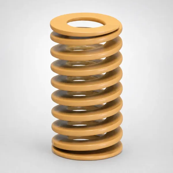
The same discipline applies to mold components. Inserts, cores and cavity blocks are machined to ±0.002 mm geometry and delivered with material certificates. Standard parts like ejector pins, core pins and mold springs ship in 3 to 7 days, so a trial-phase correction rarely waits on components.
For the full picture on tolerances down to ±0.002 mm, read How to Hold 0.002 mm Precision Mold Tolerances.
Where Shrinkage Compensation Goes Wrong
Most compensation failures are not material science failures. They are process failures in the mold design chain, and 5 patterns repeat across scrapped tools.
First, a single global rate applied to the whole cavity. This misses the 0.3% to 0.5% flow-transverse delta and the 0.4% to 0.6% far-from-gate gradient. Second, datasheet rates used without geometry correction.
Third, steel thermal growth ignored on low-shrink materials below 1.0% shrinkage. Fourth, no trial measurement loop on critical dimensions above ±0.05 mm. Fifth, correction cuts made without re-measuring the molded part.
The cost of each failure scales with mold size. A 400 mm cavity plate cut 0.5% undersized needs weld build-up and re-machining at $2,000 to $8,000. A new plate runs $15,000 to $40,000 on a large mold. The compensation review costs nothing at the DFM stage.
Shrinkage in the DieStrike DFM Pass
DieStrike runs the shrinkage review inside the DFM pass, with feedback in 24 hours. The designer checks the material rate against the datasheet, splits flow and transverse directions, and flags thick sections and insert areas. The gate layout is confirmed with the customer on the same pass. The result is a cavity model with the allowance built in before steel is ordered.
The DFM output covers more than shrinkage. The review checks wall balance, a 0.5° minimum draft, ejection, cooling and the tolerance stack on the same pass. A part that passes DFM has a defined shrinkage strategy, not a hope that the trial will fix it. Injection molds are quoted at 2 to 4 weeks, with DFM feedback inside the first 24 hours.
DieStrike builds molds for connector and electronics programs, with customers including TE Connectivity, Amphenol, Luxshare and Dongshan Precision. The shrinkage model is part of that track record, because a connector housing at ±0.02 mm leaves no room for a guessed rate.
See the full service scope at Mold Design and DFM, and learn how part features affect moldability in How to Design for Moldability. Both pages cover the checks DieStrike runs inside the first 24 hours of a quote.
FAQ: Shrinkage Compensation in Mold Design
Q1. What is the standard shrinkage formula for cavity dimensions?
Cavity dimension equals nominal part dimension divided by one minus the shrinkage rate as a decimal. A 100.00 mm dimension at 2.0% shrinkage gives a 102.04 mm cavity. Some shops multiply by one plus the rate, so agree on the formula before quoting.
Q2. Why does shrinkage differ between flow and transverse directions?
Polymer chains and glass fibers align with the flow front during filling. Shrinkage along the flow axis is lower, and shrinkage across it is higher. The delta reaches 0.3% to 0.5% on unfilled crystalline grades like POM and PP, and drops below 0.2% on glass-filled grades.
Q3. Does mold steel thermal expansion really matter?
Tool steel expands 11 to 12 µm/m·K. A 150 mm cavity at 80°C grows 0.10 to 0.11 mm over its 20°C machined size. It matters on tolerances tighter than ±0.05 mm and on low-shrink materials where the growth rivals the shrinkage allowance.
Q4. How many trial iterations does shrinkage correction take?
One to three loops for a precision dimension, when the cavity is corrected by measured shrinkage instead of datasheet values. Each loop adds 2 to 4 weeks on a hardened cavity because the correction is cut with EDM. That is why the first-pass model matters.
Q5. What cavity precision can a moldmaker actually hold?
DieStrike holds ±0.005 mm on mold dimensions and ±0.002 mm on mold component geometry, with cavities hardened to HRC 62. The shrinkage allowance is useless without that machining capability, because a 0.04 mm formula difference is eight times the tolerance window.
The Bottom Line
A mold built to the wrong shrinkage rate is scrap, and the fix costs more than the review. DieStrike applies all five rules in the DFM pass, machines cavities to ±0.005 mm, and verifies on trial shots. IATF 16949 certified, 120+ machines.
Send us your part drawing for a DFM review with the shrinkage model included, answered within 24 hours.
KEEP READING
Related Reading
5 Mold Cooling Channel Design Tips for Faster Cycles
Mold maker's 5 cooling channel design rules: channel-to-cavity distance 2-2.
Read articleArticle5 Ways to Reduce Mold Cost Without Cutting Quality
Five proven ways to reduce injection mold cost without cutting quality: DFM before quoting, right-sized cavity count,…
Read articleArticle7 Gate Design Best Practices for Balanced Filling
Mold maker's 7 gate design rules for balanced multi-cavity filling: gate depth 50-80% of wall thickness, land 0.5-1.
Read articleArticle7 Signs Your Mold Base Needs Replacement
A guide pillar with 0.04 mm play can scrap a 32-cavity run in one shift.
Read articleNEXT STEP
Ready to Start Your Mold?
Send us your element dimensions or part numbers — our team responds within 24 hours with pricing and lead time.

Written by
Ray ChanMold Buyer's Guide Author · Precision Mold Manufacturing Specialist. Ray helps global importers, distributors and OEMs source factory-direct molds and mold parts.