
The DFM Checklist: 7 Things to Check Before Your Mold Order
Table of Contents
A part with a 0-degree vertical wall, a trapped undercut, and a gate parked on a cosmetic surface passes your customer's drawing review without a comment. It passes the mold shop's DFM review with one paragraph, and the fix costs nothing because the file has not been cut. Ship the same file straight to steel, and the fix costs a reworked core, two lost weeks, and a change order in the range of $2,000 to $6,000. That gap is the entire business case for design for manufacturability, or DFM.
DFM is the cheapest insurance in tooling because it runs before any money is spent on steel. A DFM review reads your part geometry against molding reality: can this part be filled, cooled, ejected, and measured the way the drawing claims? Catching a problem in review is a one-line comment. Catching it after steel cutting is a new mold.
This guide walks through the seven checks our engineers run on every part file. Each check comes with a number to hold your design against: draft angles, wall ratios, gate depths, shrinkage rates, and clearance limits. Use the checklist before you send the RFQ, not after the mold order lands.
The Snapshot
- A DFM review costs nothing and prevents rework worth weeks of schedule and thousands of dollars in change orders.
- Seven checks: parting line, draft, wall balance, gate position, shrinkage, undercuts, and ejection.
- Draft of 0.5-2 degrees per side, with 1 degree extra per 0.025 mm of texture etch depth.
- DieStrike returns a written DFM review within 24 hours on STEP or IGES files, before any quote is locked.
- Mold tolerances quoted at ±0.005mm standard and ±0.002mm critical only make sense if the part geometry allows them.
Why DFM Review Comes Before Quoting
Mold pricing is a function of mold risk. A shop that quotes a part it has never reviewed is pricing the optimistic case: clean geometry, balanced fill, easy ejection. The moment the file arrives with zero draft on a 40 mm deep core, the shop either eats the risk or re-quotes. DieStrike reviews the file before the quote so the number you receive covers the geometry you actually sent.
The review order matters as much as the review itself. DFM feedback should arrive before the price, because the feedback changes the price. A gate moved from a visible surface to a hidden rib changes polishing hours. A draft added to a deep core changes machining strategy. When the review comes first, you decide which fixes to take, and the quote reflects that decision.
Timing is the second reason DFM belongs before quoting. DieStrike runs a 24-hour DFM turn on new part files, and the review covers all seven checks in writing. A supplier that quotes within hours without asking a single question about geometry is quoting a drawing it has not read. The quality of the DFM feedback is a capability signal: engineers who review carefully build molds carefully.
DFM also protects the program schedule. A change order after steel cutting typically costs 2 to 3 weeks and $2,000 to $6,000 per revision at typical shop rates. The same correction caught in review costs a comment and an updated file. Multiply that by the number of revisions a real part survives, and the review pays for the mold before the mold exists.
How the 24-Hour DFM Review Works
The review starts with the files: a 3D model in STEP, STP, or IGES plus the 2D drawing with tolerances. The 3D file carries the geometry; the 2D drawing carries the callouts. A part with both files gets a complete review; a part with only a PDF gets a partial one, because shrinkage, draft, and gate placement cannot be verified from a raster.
Inside the review, the part is checked against the seven-point gate below, and every finding is written with a number attached. Instead of "draft is insufficient," the comment reads "side wall A requires 1 degree per side for a 30 mm depth, currently 0.3 degrees." Instead of "gate position is risky," the comment reads "gate on the visible face will leave a 0.3 mm vestige; move to the bottom rib or accept a polish repair step."
The output is a written report within 24 hours, plus a quotation estimate on the same pass. The report is free, and it is not a marketing document: it lists real corrections, ranked by cost impact, so you can fix the cheap ones and consciously accept the expensive ones.
What the review does not do is redesign your part. DFM flags geometry that fights the process and proposes the smallest change that makes the part moldable. The design decisions stay with your engineer, which is why the feedback must be specific enough to act on.
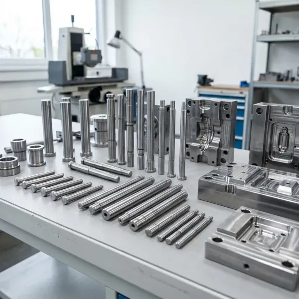
Check 1: Parting Line Placement
The parting line decides where the mold halves meet, where flash appears, and which surfaces carry witness marks. A good parting line follows the part contour, keeps cosmetic surfaces in one half, and gives the toolmaker a clean edge to trim flash against. A bad one cuts across a visible face and parks a witness line on a surface your customer will photograph.
Hold the parting line to three rules. First, keep it on an edge or a hidden face whenever the part allows it. Second, avoid stepped parting lines on deep parts unless the shut-off angle is designed in, because vertical shut-offs need a minimum of 3 to 5 degrees of angle to avoid galling and premature wear (typical practice). Third, make sure flash can be removed: a parting line buried in a blind pocket is a deburring problem for the life of the mold.
Flash itself is a dimensional story. Typical molded flash limits run 0.05 to 0.1 mm before it is classified as a defect, and the parting line determines whether flash lands on a trim edge or on a functional surface. A flash burr inside a snap-fit feature can change insertion force by 30% or more, which is the kind of failure that only shows up in assembly, not in inspection.
The review also checks the shut-off surfaces for wear. Steel-on-steel shut-offs with less than 3 degrees of angle are the first places a mold wears, and the fix is either more angle, a hardened insert, or both. Catching this in DFM keeps the wear where replacement inserts are cheap.
Check 2: Draft Angles
Every vertical face of the part needs draft, and the amount depends on depth, texture, and material. The working rule is 0.5 to 2 degrees per side on plain surfaces, 1 to 2 degrees on deep cores, and an extra 1 degree for every 0.025 mm of texture etch depth (typical practice). A 40 mm deep core with a textured surface needs closer to 2 to 3 degrees per side, not the 0.5 degrees that works on a shallow boss.
Zero-draft walls are the single most common DFM finding on connector housings and structural brackets. The mold can still fill them; the problem is ejection. Without draft, the part shrinks onto the core, and the ejector system must overcome the full contact area. The result is ejector pin marks, scratched surfaces, or a stuck part that stops the press.
Texture changes the math. Etching a mold surface to SPI D-1 or a fine leather grain adds depth to the cavity, and the plastic locks into that depth. Industry rule of thumb: add 1 degree of draft per 0.025 mm of etch depth. A deep automotive grain can require 3 degrees or more per side, and the DFM review should flag the number before the texture is specified.
Draft also interacts with tolerance. A 2-degree draft on a 10 mm tall feature moves the measured dimension 0.35 mm from top to bottom, which means the drawing must say where the dimension is measured. Without a measurement plane callout, the CMM report and the customer's gauge fight over the same feature. Our draft angle mistakes guide walks through each failure mode with the numbers.
Check 3: Wall Thickness and Ribs
Uniform wall thickness is the difference between a predictable part and a warped one. Target walls run 1.5 to 3.0 mm for typical engineering thermoplastics, and the transition between adjacent walls should stay within a 3-to-1 ratio (typical practice). A 3 mm wall meeting a 1 mm wall creates a thick section that sinks and a thin section that starves, in the same shot.
Sink marks and voids live in thick sections. A boss or rib base thicker than the nominal wall holds heat longer, shrinks more, and pulls a depression into the opposite surface. The standard fix is rib geometry: rib base at 50 to 60% of the nominal wall, rib height no more than 3 times the wall, and a fillet radius of 25 to 50% of the wall at the root. Those three numbers prevent most sink marks without any process heroics.
Warpage follows the same geometry. Unbalanced wall thickness creates unbalanced cooling, which creates differential shrinkage and a part that cups or twists. Thin-wall parts with 0.4 to 0.8 mm walls are the extreme case, where cooling dominates the cycle and the cavity/core temperature differential must stay under 5°C (typical practice). The DFM review should flag any wall that forces that regime.
Flow length matters as much as thickness. The flow-length-to-wall ratio, L/t, decides how many gates the part needs. A part with L/t over 150 to 200 typically needs a second gate or a higher-flow resin grade, and every added gate adds a witness mark somewhere. The review should state the L/t number, not just recommend "more gates."
Check 4: Gate Position and Fill
Gate position decides fill pattern, weld lines, and cosmetic quality, and it is the cheapest thing to change at DFM and the most expensive to change later. The review checks three things: where the gate sits relative to visible surfaces, whether the flow path balances, and whether the gate size matches the wall.
Cosmetic placement is the first gate question. A gate on a visible face leaves a vestige that must be polished or trimmed. The rule: put the gate on a hidden surface, a parting line edge, or a feature the customer will never photograph. If the part is cosmetic on every surface, the drawing should say which gate scar is acceptable and what size, for example "max 0.3 mm vestige."
Gate sizing follows wall thickness. Gate depth typically runs 50 to 80% of the wall thickness, and the land length 0.5 to 1.5 mm (typical practice). Oversized gates freeze late and leave big vestiges; undersized gates shear the melt and risk jetting or burn marks. The DFM review should propose a gate type per cavity: edge, pin, submarine, or valve gate, with the expected vestige.
Shear rate is the hidden gate constraint. Every resin has a shear limit, and the gate is where melt velocity peaks. Polycarbonate degrades above roughly 40,000 to 60,000 per second of shear rate, and glass-filled materials are worse (typical published limits). A gate that is too small for the shot size violates the resin limit and produces burn marks or molecular degradation. Our gate design best practices guide covers the sizing math in detail.
Weld lines follow the fill pattern. Where two flow fronts meet, a weld line forms, and its strength in glass-filled materials can drop to 40 to 60% of the bulk strength (typical published range). If the drawing places a structural feature at a weld line, the review says so, and the fix is a gate move, a flow leader, or an overflow tab.
Check 5: Shrinkage and Tolerance
Every plastic part shrinks as it cools, and the mold cavity must be cut oversized by the shrink factor of the specific resin. Shrink rates run from 0.3% for glass-reinforced PBT up to 1.8 to 2.2% for POM, with ABS and PC in the 0.4 to 0.7% band (typical published ranges). The DFM review confirms that the shrink factor is applied and that the drawing tolerances are physically achievable in the molded part.
Shrinkage is not isotropic. Flow-direction shrink differs from cross-flow shrink, and the difference grows with glass content. A 30% glass-filled PA66 part can shrink 0.3 to 0.5% in flow and 0.7 to 1.0% cross-flow, which means a round hole molds as a slight oval unless the cavity compensates. The review should flag any dimension that depends on cross-flow shrinkage.
Tolerance realism is the second half of this check. Mold features are typically held to about one-tenth of the part tolerance, so a part dimension at ±0.05 mm needs mold work well inside ±0.005 mm, which is DieStrike's standard mold tolerance, with ±0.002 mm available for critical features. A drawing that demands ±0.01 mm on a 150 mm dimension in unfilled PP is asking for physics the resin cannot deliver.
Mold steel expansion belongs in the same math. A cavity at 80°C expands 11 to 12 µm per meter per degree C, which moves a 100 mm cavity by roughly 0.07 mm against a cold measurement. Precision programs either measure at the mold temperature or compensate, and the DFM review should state which. Our shrinkage compensation guide works through a complete cavity-sizing example.
Check 6: Undercuts and Side Actions
An undercut is any feature that locks the part into the mold and prevents straight ejection. Snap-fit hooks, side holes, and internal ribs all qualify. The DFM question is not whether the undercut can be molded, but what it costs to release: a side action, a lifter, a collapsing core, or a redesigned open/close geometry.
Side actions carry a hard price tag. A slide typically adds $3,000 to $15,000 per side to the mold cost (typical range), plus cycle time for the action stroke and maintenance for the wear surfaces. Before the review accepts an undercut, it checks whether the feature can be re-drafted or re-oriented so the mold opens normally, which removes the slide at zero tooling cost.
When a side action is unavoidable, the geometry rules are specific. Slide travel should equal the undercut depth plus 2 to 3 mm of clearance so the part clears the steel (typical practice). Lifter angles run 5 to 12 degrees, and the lifter face must have enough draft to avoid dragging the part. Worn lifter faces are a top cause of part scratches and stuck parts in automotive tooling.
Shut-off undercuts are the cheaper alternative. An undercut formed by a steel shut-off between the two mold halves avoids a slide entirely, at the cost of a parting line that follows the feature contour. The review should flag which undercuts can be shut-offs and which genuinely need actions, because the difference shows up on the mold price line. Our automotive undercut design guide maps the decision per feature type.
Check 7: Ejection and Pin Layout
Ejection is where moldability fails in production, not in review. The DFM check confirms the part has a clean ejection path: enough ejector pins, sized correctly, positioned on the stiffest surfaces, with no thin pins on trapped geometry. Ejector stroke typically runs 5 to 25 mm (typical range), and the layout must clear the part completely.
Pin count follows surface area and sticking force. A deep cup needs pins around the rim, a ribbed housing needs pins under the ribs, and a thin-wall connector needs pins at the cavity corners where shrinkage locks the part onto the core. The review should state a pin plan, not just "ejector pins required," and it should flag any location where a pin mark would violate the drawing.
Thin pins are the failure mode to avoid. A 1 mm pin on a deep feature bends, and a bent pin becomes a galling pin, then a broken pin, then a 64-cavity mold stopped mid-shift. When the geometry forces thin pins, the answer is either more pins of slightly larger diameter, ejector sleeves around a core pin, or a stripper plate. The DFM review should catch the geometry that forces thin pins before the mold is built.
Pin-to-bore clearance and material matter at this stage too. Standard clearance runs 0.02 to 0.04 mm (typical), pins are typically SKD61 or H13 at HRC 48-52 for standard service and SKH51 at HRC 60-63 for high-wear runs, and coated pins extend life 2 to 3 times on glass-filled resins (typical). Specifying the pin grade and coating in the RFQ prevents the cheapest possible pin from failing in month two. See our ejector pin marks guide and the core pin versus ejector pin comparison for the selection details.

Material and Steel Match
The DFM review checks resin and mold steel together, because the pair decides tool life and part defects. Glass-filled resins need wear-resistant steel; transparent parts need polishable stainless; high-temperature resins need heat-treated hot-work steel. Matching them at the DFM stage prevents premature mold wear and cosmetic rejects.
Glass and mineral fillers are the wear problem. A 30% glass-filled PA66 wears an uncoated P20 cavity measurably within 100,000 shots, while H13 with a PVD or nitriding treatment holds the surface for several times longer (typical practice). If the resin is abrasive, the review should push the steel and coating decision into the quote, not leave it for the mold maker to decide cheap.
Transparent and optical parts flip the priority. Polycarbonate lenses and clear housings need corrosion-resistant, polishable steel, typically S136 at HRC 48-52 polished to SPI A-1, because any pit or surface defect becomes a visible artifact. The review should flag whether the drawing demands SPI A-1 and confirm the steel can hold it.
The table below summarizes the resin-to-steel match used in our DFM reviews. Values are typical practice, and the final call belongs to the program's cost and life targets.
| Resin family | Typical shrink range | Mold steel match | DFM watch item |
|---|---|---|---|
| ABS, HIPS | 0.4-0.7% | P20 pre-hardened | Sink marks over bosses and ribs |
| PC, PC/ABS | 0.5-0.7% | P20, S136 for optical | Gate shear rate, residual stress |
| PA66, PA6 | 1.2-1.8% | P20, H13 for long runs | Moisture, flash at shut-offs |
| PA66 + 30% GF | 0.3-0.6% (flow) | H13 hardened, coated | Abrasive wear on gates and cores |
| POM (acetal) | 1.8-2.2% | P20 hardened | Large shrink, dimensional drift |
| PBT, PET | 0.3-0.8% | H13 for long runs | Crystallinity, warpage |
| PMMA (acrylic) | 0.3-0.6% | S136, SPI A-1 polish | Surface defects, gate vestige |
← swipe to scroll →
Values are typical published ranges for engineering thermoplastics. Confirm the exact grade data sheet with your resin supplier.
Steel selection interacts with tolerance. A critical dimension at ±0.002 mm needs a stable, heat-treated cavity that does not move between machining and production, which is why DieStrike specifies HRC 62 for critical inserts and runs wire EDM at ±0.002 mm for the finish pass. Our P20 versus H13 versus S136 comparison covers the grade trade-offs in depth.
DFM vs DFA vs DFMA: What the Acronyms Actually Mean
Buyers and suppliers throw DFM, DFA, and DFMA around as if they were the same thing. They are three different reviews with three different owners, and mixing them up is how a part that molds beautifully still fails at assembly. The table below separates them cleanly.
| DFM (Design for Manufacture) | DFA (Design for Assembly) | DFMA (both combined) | |
|---|---|---|---|
| Focus | Single-part moldability | Multi-part integration | Part and assembly feasibility |
| Key questions | Wall thickness, draft, gating, ejection | Fastener count, orientation, insertion force, part count | Both, traded against each other |
| Failure mode if ignored | Sink marks, warpage, tooling rework | Assembly-line bottlenecks, misaligned mating features | Costly redesign at both stages |
| Typical owner | Molder / tooling engineer | Assembly / manufacturing engineer | Cross-functional design team |
← swipe to scroll →
Framework after standard DFM/DFA/DFMA literature (RJC Mold, Boothroyd-Dewhurst method). The DFM columns are the ones this checklist runs; the DFA column is the assembly review your team should run before the DFM sign-off.
The practical takeaway for a mold buyer: this checklist is the DFM column, and it is the column a mold maker is qualified to run. DFA — whether the part snaps, screws, or welds into its assembly easily — is a product-engineering review that happens at your desk, not in the tool shop. When a supplier offers a "DFMA review," ask which half they are actually qualified to sign. The ones worth paying for will tell you the DFM half is theirs and the DFA half is your engineering team's job, with the two reconciled before steel is cut.
Frequently Asked Questions
Q1. Is the DFM review really free?
Yes. DieStrike reviews part files within 24 hours at no charge, and the review includes a quotation estimate on the same pass. The review is free because the corrections it catches are cheaper for both sides than the change orders that follow a bad mold.
Q2. What files should I send for a DFM review?
Send the 3D model in STEP, STP, or IGES plus the 2D drawing with tolerance callouts. The 3D file carries the geometry and the 2D drawing carries the critical dimensions. A PDF alone gets a partial review because draft, shrink, and gate placement cannot be verified from a raster.
Q3. What is the most common DFM finding?
Missing or insufficient draft, especially on deep cores and textured surfaces. Zero-draft walls fill fine and then fail at ejection, which makes them the most expensive class of geometry problem to discover late.
Q4. Can DFM feedback change the mold price?
It should. A gate moved to a hidden surface, a draft added to a deep core, or an undercut re-routed as a shut-off all change machining hours and component cost. DieStrike reviews before quoting so the price matches the corrected geometry, not the optimistic version.
Q5. What happens if I ship a file that fails a DFM check?
You get the finding in writing within 24 hours with the specific number to fix, and you decide whether to correct the file or accept the risk. What you never get is silence followed by a change order after the steel is cut.
The Bottom Line
DFM is the cheapest insurance in tooling because it moves the cost of a geometry mistake from a $2,000 to $6,000 change order to a one-line comment. Seven checks cover the geometry that matters: parting line, draft, wall balance, gate position, shrinkage, undercuts, and ejection, and every check has a number attached.
Send your STEP or IGES file to our DFM team and get the written review within 24 hours, with a quotation estimate on the same pass. If you are comparing suppliers, use the quality of the DFM feedback as the first filter: the shop that reviews carefully is the shop that builds carefully. And when the reviewed file becomes the order, our RFQ guide shows you how to carry every DFM decision into the quote.
KEEP READING
Related Reading
5 Mold Cooling Channel Design Tips for Faster Cycles
Mold maker's 5 cooling channel design rules: channel-to-cavity distance 2-2.
Read articleArticle5 Shrinkage Compensation Rules for Mold Design
Shrinkage compensation decides mold accuracy. Five rules: material rates from 0.3% to 2.
Read articleArticle5 Ways to Reduce Mold Cost Without Cutting Quality
Five proven ways to reduce injection mold cost without cutting quality: DFM before quoting, right-sized cavity count,…
Read articleArticle7 Gate Design Best Practices for Balanced Filling
Mold maker's 7 gate design rules for balanced multi-cavity filling: gate depth 50-80% of wall thickness, land 0.5-1.
Read articleNEXT STEP
Ready to Start Your Mold?
Send us your element dimensions or part numbers — our team responds within 24 hours with pricing and lead time.

Written by
Ray ChanMold Buyer's Guide Author · Precision Mold Manufacturing Specialist. Ray helps global importers, distributors and OEMs source factory-direct molds and mold parts.