
9 Draft Angle Mistakes That Kill Moldability
Table of Contents
A connector housing mold arrived at the T1 press with every vertical face drafted at 0.3 degrees per side. The CAD template default was 0.3, and nobody changed it. The 38 mm deep core held the part like a vise.
Ejection force climbed past the press limit. The part split at the 6 mm boss. The mold spent 4 days on the bench, welding and recutting steel, while the line burned $1,800 a day in downtime. The draft angles were the last thing drawn and the first thing that failed.

Draft is the taper machined into a wall so the part can leave the steel. It is a mold design decision, not a part cosmetic, and it is decided on the drawing before steel is ordered. A missing degree of draft costs nothing in CAD and thousands in the mold shop. This article lists the 9 draft angle mistakes that kill moldability. Each carries the numbers our toolmakers check at design review and verify at T1 sampling.
The Snapshot
- Core-side vertical walls need 1-2 degrees of draft per side. The absolute floor is 0.5 degree per side.
- Texture adds about 1 degree of required draft per 0.025 mm of etch depth.
- A 40 mm deep core at 0.5 degree of draft can need 2-3 times the ejection force of the same core at 2 degrees. This is typical shop data.
- Shut-off surfaces get 1-3 degrees of draft toward the steel-to-steel contact, or they gall.
- Two degrees of draft on a 20 mm tall face moves the surface 0.70 mm per side. That is why tolerance decides the draft plan first.
Draft Angle Failure: The Scrap Math
Injection molded parts shrink 0.5-2% as they cool, depending on the resin. A part molded over a core shrinks onto the core and grips it. The grip force grows with the contact area, the depth of the feature, and the coefficient of friction between the resin and the steel. Draft is the only geometry that breaks that grip on the way out.
When the grip wins, the ejector system does the damage. Ejector pins push through thin walls, leaving witness marks and holes. Parts scuff white on the draft-free faces. The press faults on a stuck part and loses 1-3 hours per event. Reworking a drafted wall by welding and recutting steel runs $300-$1,500 per face typical, plus 2-5 days of mold downtime (industry figures).
Every number here is a draft design target, measured perpendicular to the pull direction on the drawing. Each is checked on the finished steel with a draft gage at T1. DieStrike runs this check in every DFM review and returns feedback within 24 hours. The shop holds mold size precision to ±0.005 mm under IATF 16949 across 120+ machines.
Mistake 1: Zero Draft on Vertical Walls
Zero draft is the most common draft failure, and it is always a drawing error. A wall drawn perfectly vertical reads fine in CAD and fails in the press, because nothing releases a part from a zero-taper core. The part shrinks onto the core, and the ejector pins must shear it off.
Set the floor before the part is modeled. Cavity-side walls need 0.5 degree per side as an absolute minimum, because the part shrinks away. Core-side walls need 1-2 degrees per side, because the part shrinks onto the steel. General-purpose housings and covers run 1-2 degrees per side as standard practice. Textured and polished faces need more, covered in Mistakes 3 and 9.
Why the Ejector System Pays for Missing Draft
Ejection force scales with contact area and shrink grip. Zero draft on a 25 mm deep pocket can demand 3-5 times the ejection force of the same pocket at 1.5 degrees per side. This is typical shop data. The ejector system is sized for the part weight and the draft plan together. When draft disappears, the pins must push harder, and 1-4 mm diameter pins push straight through the wall.
Check draft on the drawing with the mold closed in CAD, not by eye. At T1, run a draft gage over every vertical face and record the reading in the mold book. Our DFM review catches zero-draft walls before steel, which is why the 24-hour feedback window exists. The same discipline is documented in our moldability design rules.
Snap Check · True or False?
Draft angle is a part cosmetic — add it only if the customer asks.
True False
Answer: False. Draft is a mold design decision made on the drawing before steel is ordered. A missing degree of draft costs nothing in CAD and thousands in the mold shop.
Mistake 2: Draft Pointing the Wrong Way
Draft in the wrong direction is worse than no draft, because it turns a wall into an undercut lock. A face drafted plus 1 degree instead of minus 1 degree makes the steel wider at the bottom than the top. The part cannot slide off the core at any force. It is not a release problem. It is a mechanical lock.
Reversing 1 degree on a 30 mm tall face creates 0.52 mm of interference per side. The part is trapped in the steel, and the mold cannot open without damage. The fix is recutting the steel, welding the face, or adding a side action. All three cost more than the draft ever saved.
Reference Draft to the Pull Direction
Draft is measured from the pull direction of the mold opening, not from the part datum or the face itself. Angled part faces get compound draft. A face that looks drafted in a top view can be vertical in the pull direction. Run the CAD draft analysis with the correct pull vector before the design review. Mark the pull direction on the mold drawing.
A side action or lifter is the escape hatch for faces that cannot be drafted. Each one adds $3,000-$15,000 to the tool and 1-2 weeks to delivery, typical industry figures. Our undercut plates and side action components ship as standard parts in 3-7 days. The cheaper answer is draft applied the right way on the first drawing.
Mistake 3: Draft Too Small for the Texture
Texture eats draft. An etched surface is a field of microscopic peaks that grip the part like a file. The deeper the etch, the more draft the wall needs. The standard rule of thumb: about 1 degree of draft per 0.025 mm of etch depth, typical industry practice.
A light leather grain at 0.025 mm depth needs 1 degree extra per side on top of the base draft. A heavy grain at 0.05-0.1 mm depth needs 2-4 degrees per side. A textured core-side wall at 1 degree total scuffs the grain flat within 500-2,000 cycles. The part then shows shiny patches where the texture should be.
Draft Before Etch, Not After
Texture is applied after the steel is polished, by chemical etching or media blasting. The draft must exist on the steel before the etch, because etching follows the surface angle and cannot add taper. Stripping and re-etching a face costs $500-$2,500 plus 3-7 days of mold downtime typical. The second etch never matches the first exactly.

Put the texture spec, the etch depth, and the final draft angle on the mold drawing together. The etcher works from that block of data. If the texture grade is not fixed at quote time, design for the deepest grade in the range. Note it in the mold book. Reducing texture later is cheap, and adding it is not.
Mistake 4: Draft on One Wall, None on the Opposite
Drafting one side of a wall and leaving the opposite side vertical moves the nominal wall thickness and shifts the part dimension. The mold maker cuts the cavity to the drawn angles. The part comes out with a tapered wall, thick at one end and thin at the other. It lands off the print dimension, even though every individual face is drafted.
Two degrees of draft on a 15 mm tall wall moves the surface 0.52 mm per side. On a 2.5 mm nominal wall, that is a 21% thickness swing from one end to the other. The thick end sinks and warps. The thin end fills with hesitation marks. A ±0.1 mm print tolerance on that face is gone before the first shot.
Split the Draft or Keep It Off the Critical Face
The fix is to allocate draft to both walls or to keep the critical face vertical. Splitting the draft, 1 degree on each side of a wall that needs 2 total, holds the centerline in place. Keeping the critical face at 0.5 degree or less moves the rest of the draft to the opposite face. That protects the dimension.
On pockets and bosses the same rule applies. Drafting only the cavity side of a pocket leaves the core side vertical, and the part hangs on the core. Draft the core and cavity sides of the pocket with the same total. Then verify the wall thickness stays within 25% of nominal along the full height.
Mistake 5: Under-Drafting Deep Cores and Ribs
Depth multiplies the shrink grip. A shallow feature releases with almost no draft, so designers under-draft deep features by habit. Cores deeper than 25 mm accumulate grip along their full height. So do ribs taller than 3 times their base thickness, and bosses taller than their outside diameter.
Cores 25-40 mm deep need 1-2 degrees per side minimum. Cores beyond 40 mm need 2-3 degrees or a stepped draft. Doubling the depth doubles the grip area and roughly doubles the ejection force. A rib at 0.5 degree per side is acceptable up to 3 times its base thickness. Beyond that, go to 1-1.5 degrees per side.
Stepped Draft for Very Deep Walls
Stepped draft keeps the top of a deep wall at the print dimension and adds taper lower down. The wall runs vertical for the first 20-30% of its height, then steps to 1-2 degrees. It leaves a visible step line on the part, so it belongs on non-cosmetic faces only. The step is machined with a form cutter or EDM and measured with the draft gage at T1.
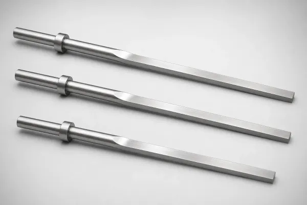
Rib pockets are machined with rib cutters, and the cutter angle sets the draft. A 1 degree rib cutter is standard stock. 0.5 degree cutters exist, but they wear fast and chatter on deep passes. Design ribs to the cutter you can buy, or expect a recut. Ribs that stick bend or shear at ejection, and the fix is a new rib pocket in the steel.
Mistake 6: No Draft on Shut-Off Surfaces
A shut-off is where core steel meets cavity steel face to face to form an opening in the part, like a window, a through-hole, or a pocket edge. The two steel faces touch on every cycle. They need draft toward the shut-off contact, typically 1-3 degrees, so the faces slide cleanly instead of grinding.
Without draft, the shut-off faces gall. Steel-to-steel friction welds micro-burrs onto the edges, the shut-off grows a witness line, and flash appears at 0.05-0.2 mm thick on the part edge. Galling shows up within 5,000-20,000 cycles typical. The mold then comes down to re-fit the shut-off, at $200-$800 per surface plus 2-4 days of downtime. Industry figures.
Draft Every Steel-to-Steel Contact
Shut-offs appear around through-holes and on the outside of parting line windows. They also sit on lifter and slide faces, and at the base of core pins that pass through the cavity. Each contact face gets draft toward the mating steel, never away from it. A shut-off drafted away from the contact creates a knife edge that chips on the first close.
Lifters and slides run on angled faces with the same rule: 1-3 degrees on the sliding surfaces, polished along the travel direction. Angle pins that drive slides are drafted 5-15 degrees and hardened to HRC 58-62. The draft plan for every moving steel member belongs on the mold assembly drawing, not in the machinist's memory.
Mistake 7: Draft That Blows the Tolerance
Draft moves the surface. A face drafted at angle theta over a height h shifts its position by h times tan(theta) at the narrow end. Two degrees on a 20 mm face moves the surface 0.70 mm per side. That consumes a ±0.1 mm print tolerance 7 times over. Draft and tolerance fight over the same millimeters, and the draft plan must be written around the tolerance first.
A ±0.1 mm tolerance on a 15 mm tall face allows about 0.38 degree of draft per side. Beyond that, the tolerance is consumed at the narrow end. Most functional fits cannot survive that little taper. The designer moves the tolerance, moves the datum, or moves the draft.
The Three-Way Split
Three answers exist. One, put the critical face at 0.25-0.5 degree and move all the needed draft to the opposite face. Two, shift the nominal dimension so the narrow end sits at the midpoint of the tolerance band. Three, step the draft below the critical zone, leaving the top of the face at print and tapering below the functional area.
The tolerance allocation happens before the draft is drawn, and both go into the DFM review. DieStrike holds mold size precision to ±0.005 mm and part geometry to ±0.002 mm, so the steel can hold whatever the drawing says. The drawing has to say the right thing, and that is a draft-and-tolerance decision made together.
Mistake 8: Draft on the Outside, None on the Inside
Draft is easiest to see on the outside walls, so internal details get skipped. Blind holes, through holes, snap latches, internal ribs, and threaded bosses all shrink onto their pins and cores. The inside of the part grips steel harder than the outside, because the shrinkage is radial and the pin is surrounded.
Blind holes and through holes need draft on the pin side: 0.5-1 degree per side typical, and 1-2 degrees on deep pins. A hole drafted on the cavity side only tapers the wrong way, and the pin still grips the full depth. Core pins 1-6 mm in diameter are drafted on the pin itself and polished along the pull direction.
Snap Latches and Bosses
Snap latches drafted at 0 degree bind during ejection and crack at the hinge. A latch arm 1.2 mm thick with no draft fatigues at the root within 10,000-50,000 cycles typical and snaps off in service. Draft the latch faces 1-1.5 degrees per side and keep the hinge radius above 0.25 mm to spread the bending stress.
Bosses grip two ways: the outside shrinks onto the cavity wall, and the inside shrinks onto the core pin. Draft the boss outside at 0.5-1 degree and the pin at 1-2 degrees. Tall bosses use ejector sleeves instead of pins, because a pin pushing on a tall thin boss wall pushes through. Our ejector sleeves and pins cover the tall-boss case as standard tooling.
Mistake 9: Draft Not Matched to Mold Finish
Mold finish sets the friction between the resin and the steel. A mirror-polished face slides easier than an EDM face, and the required draft follows the finish. A core-side wall polished to SPI A-1 mirror (Ra 0.05-0.1 μm) releases at 0.5-1 degree. The same wall with an EDM finish at Ra 1.6-3.2 μm needs 1-1.5 degrees, because the craters grip the part like a file.
Surface roughness roughly doubles the friction contribution against the shrink grip, typical. So every finish change is a draft change. The finish spec goes on the drawing with the draft angle, and both are machined together. Polish first, measure the draft with a gage, then etch if the texture spec calls for it.
Polish Direction and Coatings
Polish along the pull direction, never across it. A cross-polish leaves scratch lines perpendicular to ejection, and each scratch is a mechanical lock. The polisher's final pass runs parallel to the draft, and the mold book records the direction with the finish grade.
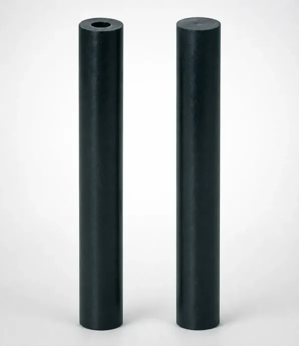
Coatings change the friction number without changing the draft. Chrome and DLC on cores cut ejection force by 20-40% typical, which rescues a marginal tool between rebuilds. They do not replace draft, and a coated face still needs its 0.5-1 degree. High-gloss optical parts add a second rule. The cavity side needs 0.5-1 degree too, so the released part does not drag across the polished cavity face.
Draft Angle Reference Table
The numbers below are the starting points our toolmakers use in DFM review. Verify each one against the resin, the texture spec, and the print tolerance before steel is cut.
| Surface or Feature | Draft per Side | Reference | Note |
|---|---|---|---|
| Core-side vertical wall | 1-2 degrees | Pull direction | Part shrinks onto the core |
| Cavity-side wall | 0.5-1 degree | Pull direction | Part shrinks away from the cavity |
| Textured surface | Base + 1 degree per 0.025 mm etch depth | Texture grade | Heavy grain at 0.1 mm needs 3-4 degrees |
| Shut-off surface | 1-3 degrees | Toward the steel contact | Prevents galling and flash |
| Rib | 0.5-1 degree | Rib cutter angle | Deep ribs over 3x base: 1-1.5 degrees |
| Boss outside | 0.5-1 degree | Wall thickness check | Keep wall within 25% of nominal |
| Boss core pin | 1-2 degrees | Pin side | Radial shrink grips the pin |
| EDM-finished wall | 1-1.5 degrees | Ra 1.6-3.2 μm | Craters grip the part |
| Mirror-polished wall | 0.5-1 degree | SPI A-1, Ra 0.05-0.1 μm | Polish along the pull direction |
← swipe to scroll →
Table: typical industry figures; verify against your program.
Snap Check · True or False?
The deeper the surface texture, the more draft you need.
True False
Answer: True. Texture grabs the steel — the deeper the texture, the more taper the wall needs to release without drag marks. That is Mistake 3 in this guide.
FAQ: Draft Angle in Mold Design
Q1. What is the minimum draft angle for injection molding?
The floor is 0.5 degree per side on cavity-side walls, measured from the pull direction. Core-side walls where the part shrinks onto the steel need 1-2 degrees per side. General-purpose parts are drawn at 1-2 degrees per side, and textured or highly polished faces get more.
Q2. How much draft does a textured surface need?
About 1 degree per 0.025 mm of etch depth on top of the base draft. A light grain at 0.025 mm adds 1 degree, and a heavy grain at 0.05-0.1 mm adds 2-4 degrees. Draft is machined before etching, so the etch depth and draft angle are fixed together on the drawing.
Q3. Does draft affect the part tolerance?
Yes. Draft moves the surface by h times tan(theta) at the narrow end. Two degrees on a 20 mm face moves it 0.70 mm, which overruns most ±0.1 mm tolerances. Put the critical face at 0.25-0.5 degree, move the draft to the opposite face, or shift the nominal dimension before the mold is quoted.
Q4. What draft do deep cores need?
Cores 25-40 mm deep need 1-2 degrees per side minimum, and cores beyond 40 mm need 2-3 degrees or a stepped draft. Doubling the depth roughly doubles the ejection force, so deep features get the upper end of the range.
Q5. What happens if a part has no draft?
The part grips the core, ejection force spikes, and ejector pins push through thin walls. Reworking a drafted wall by welding and recutting steel runs $300-$1,500 per face typical plus 2-5 days of downtime. That is why the draft plan is reviewed before steel is cut.
The Bottom Line
Draft is a mold design number with a measurement. Every one of the nine mistakes is cheaper at the drawing than in the steel. The angles are verified at T1 with a draft gage and recorded in the mold book. The tool then runs its whole life on the numbers it was cut to.
Send us your part drawing for DFM feedback within 24 hours, or get draft and tolerance advice with a cost breakdown within 48 hours.
KEEP READING
Related Reading
5 Mold Cooling Channel Design Tips for Faster Cycles
Mold maker's 5 cooling channel design rules: channel-to-cavity distance 2-2.
Read articleArticle5 Shrinkage Compensation Rules for Mold Design
Shrinkage compensation decides mold accuracy. Five rules: material rates from 0.3% to 2.
Read articleArticle5 Ways to Reduce Mold Cost Without Cutting Quality
Five proven ways to reduce injection mold cost without cutting quality: DFM before quoting, right-sized cavity count,…
Read articleArticle7 Gate Design Best Practices for Balanced Filling
Mold maker's 7 gate design rules for balanced multi-cavity filling: gate depth 50-80% of wall thickness, land 0.5-1.
Read articleNEXT STEP
Ready to Start Your Mold?
Send us your element dimensions or part numbers — our team responds within 24 hours with pricing and lead time.

Written by
Ray ChanMold Buyer's Guide Author · Precision Mold Manufacturing Specialist. Ray helps global importers, distributors and OEMs source factory-direct molds and mold parts.