
Ejector Pin vs Core Pin: When Each Wins
Table of Contents
A 0.50 mm core pin snapped on cycle 4,000 and a 32-cavity connector tool sat down for 18 hours. The replacement pin cost about $3. The lost production, the re-qualification, and the manual sorting of 120,000 molded parts cost closer to $18,000. That math is why the ejector pin versus core pin decision is never a spare-parts afterthought.
The Snapshot
- Core pins hold size tolerances of ±0.002 to 0.005 mm and form holes. Ejector pins run in 0.02 to 0.04 mm clearance fits and push parts out.
- SKH51 ejector pins reach HRC 60 to 63. Nitrided SKD61 core pins run HRC 45 to 52.
- Bending risk climbs when the pin length-to-diameter ratio passes 10:1.
- DIN 1530 ejector pins cover 0.8 to 25 mm diameters. Precision core pins go below 0.5 mm.
- DieStrike ships standard ejector and core pins in 3 to 7 days and returns DFM feedback within 24 hours.
This guide compares the two pins on function, tolerance, steel, failure mode, price, and lead time. It ends with a selection tree your mold designer can work from today.
Function: Form Versus Release
Core Pins Form Geometry
A core pin is a forming member. It defines the inside diameter of a hole, a boss bore, or a slot. The plastic shrinks onto the pin during cooling, so the pin sets the internal geometry of the feature. In a connector housing with 12 blind holes, the tool typically carries one core pin per hole per cavity.
The forming diameter is ground to a size tolerance of ±0.002 to 0.005 mm, typical for precision tooling. Straightness and roundness stay in the same band. Draft of 0.25 to 1.0 degree per side is added when the hole depth allows it, so the part releases without dragging. Zero-draft holes under 5 mm deep need coated pins or an ejector sleeve to avoid scoring.
Ejector Pins Release the Part
An ejector pin is a push rod. It transfers force from the ejector plate to the molded part and lifts the part off the core. It rarely defines critical geometry. The pin face leaves a witness mark, which is why ejector pins avoid class-A surfaces.
Pins are sized so push stress stays inside the resin limit. Typical allowable ejector stress runs 15 to 40 MPa depending on the material. A 2.0 mm pin at 20 MPa carries about 63 N of push force. Ejector stroke is typically 5 to 25 mm. Standard diameters sit between 0.8 and 16 mm.

DieStrike holds ejector plate motion to ±0.005 mm mold precision, so pin travel stays consistent across the 120+ machines on the floor. Consistent travel keeps witness marks uniform from the first shot to the millionth.
Tolerance and Fit: The Real Divider
Core Pins Are Ground to Size
Core pins are specified by formed diameter. A 1.50 mm hole in the drawing needs a 1.50 mm pin within ±0.002 to 0.005 mm, typical industry tolerance. The pin is centerless ground and lapped. Runout and straightness are verified against the forming surface, not the head.
When the pin also slides for ejection, the working fit gets looser. That is the trade. A pin that moves in the plate cannot hold the same size band as a fixed pin, because clearance appears at the land.
Ejector Pins Are Specified by Fit
Ejector pins are specified by mating clearance. The working land runs 0.02 to 0.04 mm clearance in the core plate, typical for standard ejector systems. Head clearance sits at 0.05 to 0.1 mm so the pin does not bind when the plate returns.
Tight classes of 0.005 to 0.015 mm are used for thin pins below 1.0 mm diameter, where column stability matters more than free travel. Loose classes are never used on the forming diameter of a core pin, because the hole would walk.
DieStrike documents every fit class on the drawing and verifies it with pin gauges at assembly. Mold part geometry holds ±0.002 mm, which is tighter than most fit charts assume.
Swapping roles is the fastest way to wreck a tool. A core pin used as an ejector wears its land and loses the hole tolerance within 50,000 cycles. An ejector pin used as a core pin cannot hold ±0.005 mm, because its shank tolerance band is 0 to -0.01 mm, ten times wider. Order the part for the job it does.
Steel and Hardness Compared
Steel choice decides wear life, toughness, and the failure mode you will see first. Three grades cover most precision molds, and their hardness bands are part of the spec, not an afterthought.
SKD61: The Nitrided Workhorse
SKD61 is a hot-work die steel, the same family as H13. Nitrided core pins run at HRC 45 to 52 with a case depth of 0.1 to 0.3 mm, typical industry figures. The tough core absorbs shock, so SKD61 suits core pins that see side loads and temperature swing.
SKH51: High-Speed Steel for Wear
SKH51 is M2 high-speed steel. Ejector pins made from it reach HRC 60 to 63, which resists abrasive wear from glass-filled resins. A 30% glass-filled PA66 compound will wear an HRC 52 pin visibly at the land within 200,000 cycles, typical field data.
H13: The Balanced Option
H13 at HRC 46 to 52 balances toughness and polishability. It is a common choice for larger core pins and for pins that also carry cooling. DieStrike hardens cavity steel to HRC 62, so mating components are specified to outlast or match that level.

Coating moves the needle on wear jobs. TiN at 2 to 4 µm cuts friction on glass-filled compounds. Nitriding first, then coating, is the sequence that survives above 500,000 cycles on abrasive resins.
| Steel | Typical Hardness | Best Role | First Failure Mode |
|---|---|---|---|
| SKD61 (nitrided) | HRC 45 to 52 | Core pins under side load | Wear, then bending |
| SKH51 (M2 HSS) | HRC 60 to 63 | Ejector pins on filled resins | Breakage at the head fillet |
| H13 | HRC 46 to 52 | Large core pins, cooled pins | Heat checking on hot tools |
← swipe to scroll →
Typical industry figures. Verify against your own resin, mold temperature, and cycle count.
Failure Modes: Bend, Wear, Break
Bending and Buckling
Slender pins buckle. Once the length-to-diameter ratio passes 10:1, a side load of even 50 N can bow a 1.0 mm pin. Asymmetric gating is the usual source of side load, because it pushes the core sideways during fill.
The fix is structural. Support bushings, stepped diameters, or a thicker pin under the head each add stiffness. DieStrike reviews pin layout against fill balance during DFM, with feedback returned in 24 hours.
Wear and Galling
Wear shows first at the land, where the pin slides against the core plate. A land that opens by 0.01 to 0.02 mm starts leaking flash onto the part. Galling happens when clearance is too tight and the two steels cold-weld.
Nitriding adds a 0.1 to 0.3 mm case. TiN at 2 to 4 µm cuts friction further on glass-filled jobs. Both are standard options on ejector and core pins.
Breakage at the Head
Most pin fractures start at the head fillet. The 0.3 mm fillet radius typical of DIN heads is a stress raiser, and fatigue accumulates over 500,000-plus cycles. Breakage at the fillet drops the pin head into the ejector plate and stops the press.
Verification is simple. Magnetic particle inspection or a hardness check at the fillet catches the bad batch before it reaches the tool. Replacing a worn pin costs $3 to $60. Replacing a cracked cavity costs a mold rebuild.
Sticking and Pulling
Sticking happens when the part shrinks onto a core pin with no draft. The ejector pin pushes, the part deforms, and the pin face dimples the surface. Draft of 0.25 to 1.0 degree per side, or a TiN coating, cuts release force by up to 30%, typical field results.
Pulled cores show up as oval holes. The core pin deflects under melt pressure, and the hole comes out 0.01 to 0.03 mm over size on the gate side. Balanced gating and a stiffer pin are the fixes, not a bigger tolerance.
DIN and ISO Size Chart
Standard sizes keep the parts room simple and the lead time short. The table below lists the ranges that cover most precision molds, with typical industry figures.
Reading a Pin Spec
Three lines on the drawing decide the pin: diameter tolerance, fit class, and steel. Everything else is execution. A core pin line reads 1.500 +0.002/-0.002 mm, SKD61 nitrided. An ejector pin line reads 3.0 mm, SKH51, 0.02 to 0.04 mm clearance.

Order the pin exactly as the drawing reads. A core pin ordered to ejector tolerances will not hold the hole. An ejector pin ordered to core tolerances will gall in the plate before the first thousand cycles.
| Parameter | Ejector Pin (DIN 1530) | Core Pin (Ground to Print) |
|---|---|---|
| Diameter range | 0.8 to 25 mm | 0.3 to 25 mm typical |
| Length range | 40 to 400 mm | 10 to 200 mm typical |
| Diameter tolerance | 0 to -0.01 mm shank, 0.02 to 0.04 mm land clearance | ±0.002 to 0.005 mm forming surface |
| Straightness | 0.005 mm per 100 mm typical | 0.002 to 0.005 mm per 100 mm typical |
| Hardness | SKH51 HRC 60 to 63 | SKD61 nitrided HRC 45 to 52, H13 HRC 46 to 52 |
| Surface finish | Ra 0.2 to 0.4 µm, nitriding optional | Ra 0.2 to 0.4 µm lapped, coating optional |
← swipe to scroll →
Typical industry figures. DieStrike custom core pins hold ±0.002 mm geometry on diameters from 0.3 mm up.
When a Core Pin Wins
Blind Holes and Bearing Bores
Any hole that must hold size wins with a core pin. Connector housings, standoffs, and bearing bores carry size tolerances of ±0.005 mm or tighter, which a moving ejector pin cannot hold. The core pin is fixed, ground to size, and lapped.
Deep holes push the length-to-diameter limit. A 0.8 mm pin forming a 12 mm hole runs at 15:1, so it gets a support bushing or a stepped shank. DieStrike custom core pins hold ±0.002 mm geometry on diameters from 0.3 mm up.
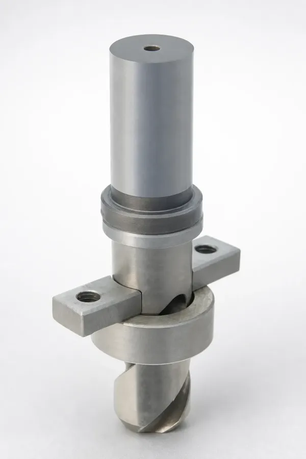
Micro pins below 0.5 mm need the same care as the big ones. Runout at the tip, not diameter, usually decides the hole roundness at 0.5 mm pitch connector layouts.
Undercut and Angled Features
Core pins also form undercuts when they pull at an angle. A lifter or a cam-mounted core pin withdraws along the feature axis, releasing the hook or the notch. The pin steel takes the full melt pressure, so toughness matters more than raw hardness here.
Threaded and Stepped Cores
Threaded features need rotating or collapsible cores. A collapsible core with three segments forms a thread and collapses 0.3 to 0.5 mm radially before ejection. Segment steel is usually SKD61 at HRC 50 to 54, nitrided, because the segments flex on every cycle.
Stepped cores form two diameters in one pin. The step creates a shoulder that the part grips, so the pin needs the same draft discipline as the hole wall. The step radius is held at 0.1 to 0.2 mm to avoid a stress line in the part.
When an Ejector Pin Wins
Ribs, Bosses, and Thin Walls
Ejector pins win wherever a part needs push-off force. Ribs 0.5 to 1.0 mm thick are ejected with blade pins or small round pins, typically 1.0 to 3.0 mm in diameter. The witness mark lands on the rib, not on a class-A face.
Thin-wall housings eject with many small pins rather than few large ones. Spreading the load keeps push stress below the 15 to 40 MPa typical limit. A 40 mm part may carry 12 pins of 1.5 mm.
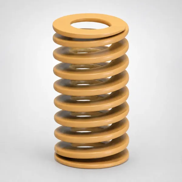
Pin count is a cost lever too. Each extra pin adds a hole, a fit, and a spare to stock. DieStrike's DFM review trims pin counts where stress allows, cutting tool cost without risking ejection.
Where Witness Marks Are Allowed
Ejector pins are the cheapest release mechanism in the tool. They cost less than lifters, sleeves, or air valves, and they are replaceable in minutes. The trade is the mark, held to 0.05 to 0.1 mm typical on non-cosmetic surfaces.
Ejector sleeves take over for round bosses where a solid pin would mark the bore. A sleeve with 0.02 to 0.05 mm wall pushes the boss shoulder while the inner core pin forms the hole. That is the classic two-pin team.
Tip Shapes and Their Limits
Tip shape is part of the spec. Flat tips suit most ribs and bosses. Stepped tips support a thin wall over a longer span. Spherical tips reduce the mark on soft resins but shift the push point.
A flat tip on a 2.0 mm pin carries about 3.14 mm² of push area. At 20 MPa that is 63 N of force. If the effective area drops to 1.5 mm², the same 20 MPa yields only 30 N. Pin count must climb to stay inside the 15 to 40 MPa limit.
How the Two Pins Work Together
The Classic Team on a Boss
A boss with a center hole shows the partnership. The core pin forms the hole. The ejector sleeve or the surrounding pins push the boss off the pin. Clearance between the sleeve and the core pin runs 0.02 to 0.04 mm, typical.
The ejector plate stroke of 5 to 25 mm must exceed the pin engagement, or the part stays on the core. Return pins push the plate back before the mold closes, and springs cushion the return at high cycle rates.
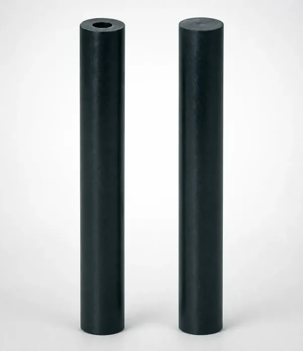
DieStrike assembles the whole system, from ejector plate to pin tips, on the same ±0.005 mm mold tolerance. The ejector and core pin sets are documented in the mold book, so a spare pin drops in without a re-qualification run.
Cooling Around Pins
Pins block cooling. Every pin hole removes steel that could carry a water line, so pin-dense areas run hotter. Water lines are typically 6 to 10 mm in diameter. They sit 2 to 3 mm from the cavity wall, with pin holes routed between them.
Hot pins mean slower cycles and more shrinkage on the pin. A core pin running 15 °C hotter than the cavity adds measurable cycle time on a 30-second part. Pin layout and cooling layout are designed together, not sequentially.
Guided and Returning Systems
Long ejector pins get guide bushings at the plate. A 250 mm pin bends under its own return speed without guidance, and the land wears oval within 20,000 cycles. Guided pins hold land roundness at 0.003 mm typical.
Return stroke is tuned at T1 sampling. DieStrike documents ejector stroke, return pin length, and spring preload in the mold book, so the setup team repeats the same motion on every run.
Price and Lead Time
Standard Versus Custom
Standard ejector pins are commodity parts. A 3.0 mm by 100 mm SKH51 pin runs about $2 to $8, typical industry pricing, and stocks are deep. Standard core pins in common sizes sit in the same band when they are cut from stock and ground.
Custom core pins cost more. A ground-to-print pin with nitride runs $15 to $60 typical, depending on diameter, length, and coating. TiN adds $5 to $15. The premium buys the ±0.002 to 0.005 mm tolerance band and the right steel.
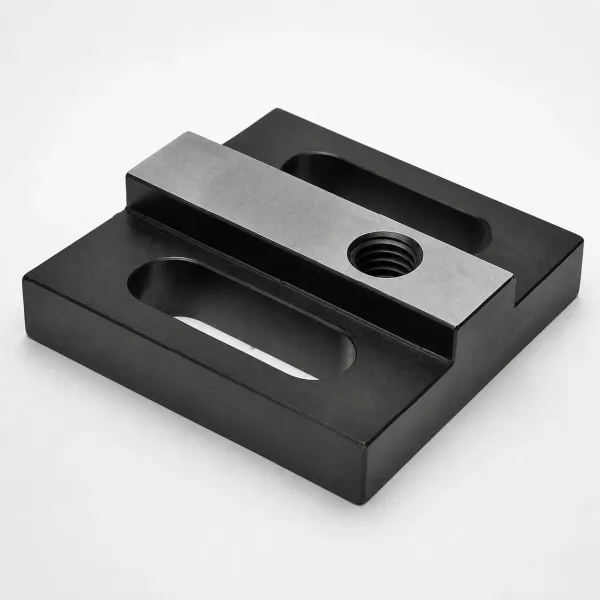
Lead time follows the same split. DieStrike ships standard ejector pins, core pins, sprue bushings, punches, mold bases, springs, and guide pins in 3 to 7 days. Custom ground pins are quoted with the drawing and usually join the standard parts on the next shipment.
| Item | Typical Price (Industry) | Typical Lead Time | DieStrike |
|---|---|---|---|
| Standard ejector pin, 3.0 x 100 mm, SKH51 | $2 to $8 | 1 to 7 days | 3 to 7 days |
| Standard core pin, common size, SKD61 | $3 to $10 | 1 to 7 days | 3 to 7 days |
| Custom core pin, ground to print ±0.002 to 0.005 mm | $15 to $60 | 7 to 14 days | Quoted after DFM, 24 h feedback |
| Complete injection mold | Project based | 4 to 8 weeks typical | 2 to 4 weeks |
← swipe to scroll →
Industry price bands are typical figures for standard stocked pins. DieStrike returns a pin selection review with a cost breakdown within 48 hours.
That is the difference between a $3 pin ordered blind and a $3 pin ordered right. The review costs nothing, and it catches the tolerance, steel, and coating mistakes before steel is cut.
Selection Decision Tree
Run the part through these six gates. Each gate either routes the feature to a pin type or flags a risk before steel is cut.
- Formed hole, bore, or slot? Route to a core pin. Flat push-off surface? Route to an ejector pin.
- Hole size tolerance of ±0.005 mm or tighter? The core pin must be fixed or guided. A sliding ejector pin cannot hold that band.
- Length-to-diameter ratio above 10:1? Add a support bushing, a stepped shank, or a larger diameter. Never let the pin cantilever.
- Glass fill at 30% or more? Specify SKH51 at HRC 60 to 63 or a TiN/TiAlN coating on the land.
- Witness mark on a class-A face? Move the ejector to a rib, an edge, or a hidden face. Keep the mark off cosmetic surfaces.
- Both jobs on one pin? Accept the looser hole tolerance and the wear at the land, or split the function. DieStrike's mold design review settles the split within 24 hours, before the mold base is ordered.
Each gate answer maps to a drawing line. Gate 2 writes the tolerance callout. Gate 4 writes the steel and coating. Gate 5 moves the pin location. A drawing that answers all six gates survives DFM review in one pass, which is the 24-hour target at DieStrike.
The tree ends where the drawing starts. Pin type, diameter, tolerance, steel, coating, and spare stock go on the print, and the toolroom builds to the print.
FAQ
Q1. Can a single pin form a hole and eject the part? Yes, when the core pin rides on the ejector plate. The trade is that the hole tolerance loosens to the fit class, typically 0.02 to 0.04 mm, and the land wears faster. For holes at ±0.005 mm, keep the jobs separate.
Q2. Which hardness should I order? Match the pin to the wear source. Ejector pins in SKH51 run HRC 60 to 63. Core pins in nitrided SKD61 run HRC 45 to 52, and H13 sits at HRC 46 to 52. DieStrike hardens cavity steel to HRC 62, so pins are specified to survive against it.
Q3. How do I size an ejector pin? Divide the ejection force by the allowable push stress, 15 to 40 MPa typical depending on resin. A 2.0 mm pin at 20 MPa carries about 63 N. For a 2,000 N ejection load, plan on 32 pins of 2.0 mm, or fewer larger pins if the layout allows.
Q4. What is the lead time for custom pins? Standard ejector and core pins ship in 3 to 7 days from DieStrike. Custom ground core pins are quoted after the DFM review, with selection advice and cost breakdown within 48 hours. A complete injection mold ships in 2 to 4 weeks.
The Bottom Line
Pin selection is a quality gate. Core pins form holes at ±0.002 to 0.005 mm. Ejector pins release parts through 0.02 to 0.04 mm clearance. Wrong calls surface as scrap and downtime. DieStrike, an IATF 16949 shop with 120+ machines, holds both sets to ±0.005 mm mold precision.
Send us your part drawing and get a pin selection review with a cost breakdown within 48 hours. Standard pins ship in 3 to 7 days.
KEEP READING
Related Reading
5 Mold Cooling Channel Design Tips for Faster Cycles
Mold maker's 5 cooling channel design rules: channel-to-cavity distance 2-2.
Read articleArticle5 Shrinkage Compensation Rules for Mold Design
Shrinkage compensation decides mold accuracy. Five rules: material rates from 0.3% to 2.
Read articleArticle5 Ways to Reduce Mold Cost Without Cutting Quality
Five proven ways to reduce injection mold cost without cutting quality: DFM before quoting, right-sized cavity count,…
Read articleArticle7 Gate Design Best Practices for Balanced Filling
Mold maker's 7 gate design rules for balanced multi-cavity filling: gate depth 50-80% of wall thickness, land 0.5-1.
Read articleNEXT STEP
Ready to Start Your Mold?
Send us your element dimensions or part numbers — our team responds within 24 hours with pricing and lead time.

Written by
Ray ChanMold Buyer's Guide Author · Precision Mold Manufacturing Specialist. Ray helps global importers, distributors and OEMs source factory-direct molds and mold parts.