
How to Design Undercuts for Automotive Parts
Table of Contents
A Tier 1 buyer approved an automotive door trim drawing with a snap hook at zero draft on the pull face. The mold quote came back at $42,000 with a lifter. The buyer rejected it as too expensive. The redesign moved the hook 8 mm and added 2 degrees of draft. The final tool cost $31,500. One undercut decision changed the program price by $10,500, roughly 25 percent.
Undercuts are the most expensive geometry feature in an automotive mold. Each one forces a side action, a lifter, or a redesign. Side actions add $3,000-$15,000 per side to the tool, typical industry figures. Lifters add $1,500-$6,000 per unit. When the blocked depth is 3 mm or less, the redesign is often free. This article classifies each undercut, sizes the mechanism, and shows when to tool it or eliminate it.

Undercut decisions are made in the first DFM review, before steel is ordered. The mold designer maps every feature against the pull direction. Each locked face gets a mechanism, a travel number, and a steel grade. DieStrike runs this check on every automotive mold and returns feedback within 24 hours. The shop holds mold size precision to ±0.005 mm under IATF 16949 across 120+ machines.
The Snapshot
- A 6 mm deep side hole needs 8-9 mm of side action travel, which is depth plus 2-3 mm of clearance.
- Side actions add $3,000-$15,000 per side to mold cost, typical industry figures.
- Lifter angles run 5-12 degrees. At 12 degrees, a 10 mm ejector stroke clears only 2.13 mm of undercut.
- One degree of added draft on a 20 mm face moves the surface 0.35 mm, often enough to clear a snap hook.
- DieStrike ships standard undercut plates and side action components in 3-7 days and returns DFM feedback in 24 hours.
Undercut Geometry: What Locks the Part
An undercut is any feature that prevents the part from releasing along the mold opening direction. The mold opens, the ejector pushes, and the part hangs on steel. That locked geometry is the undercut. Automotive parts carry them everywhere, because packaging function into a small volume creates blocked faces.
The common sources are snap-fit hooks, side mounting holes in bosses, internal threads, and wire clip channels. Louvers, grommet seats, and ribs perpendicular to the pull direction add more. A single connector housing can carry 4-8 undercuts across latches and alignment features. Each one is a separate mechanism decision on the mold drawing.
How the DFM Review Maps Undercuts
The mold designer starts by setting the pull direction, usually normal to the parting line. Every face is then checked for draft against that vector. Faces with zero or negative draft become undercut candidates. The check runs in CAD draft analysis first, then again on the finished steel with a draft gage at T1 sampling.
The review sorts each undercut into three buckets. The first bucket is toolable with a standard side action. The second is toolable with a lifter. The third is avoidable with a geometry change. The sort is a cost decision first, and depth, position, and draft all feed the mechanism choice. Our mold design DFM service documents every bucket in the 24-hour feedback report.
Every bucket carries a travel number and a steel grade. The DFM report lists each undercut with its mechanism and its estimated cost impact. That makes the price visible before the quote, not after. Automotive buyers use the list to challenge features that do not earn their tooling cost.
External Undercuts vs Internal Undercuts
External undercuts sit on the outside of the part, facing the cavity. Internal undercuts sit inside the part, facing the core. The distinction sets the mechanism. External undercuts use side actions that travel away from the part. Internal undercuts use lifters that ride the ejector stroke at an angle.
A door handle bezel lip is an external undercut. A latch pocket inside a connector shell is internal. External mechanisms are simpler to build and maintain, because they have their own motion. Internal ones share the ejector travel and need tighter timing with the ejector plate.
How Position Sets the Mechanism
Position relative to the parting line decides the mechanism more than depth does. Undercuts below the parting line in the moving half usually suit lifters. Undercuts on the fixed half need side actions with their own locking. A feature that crosses the parting line can sometimes be split between two mechanisms, which doubles the moving steel count.

The cost difference between the two paths is large enough to redraw for. A lifter shares the ejector plate and needs no extra press stroke. A side action needs its own cam, its own return, and its own lock. That is why internal features are cheaper to tool when the depth stays under 3 mm.
| Feature | Mechanism | Travel Source | Typical Cost | Common Automotive Parts |
|---|---|---|---|---|
| External undercut | Side action (slide) | Independent cam or hydraulic cylinder | $3,000-$15,000 per side | Bezels, housings, bumper clips |
| Internal undercut | Lifter or collapsible core | Ejector stroke at 5-12 degrees | $1,500-$6,000 per unit | Snap hooks, internal latches |
| Internal thread | Unscrewing core | Rotating core, motor or rack drive | $8,000-$20,000 per station | Sensor nuts, fluid fittings |
← swipe to scroll →
Note: cost ranges are typical industry figures and scale with travel, steel grade, and standard part package.
Side Action Design Rules
A side action carries the undercut-forming steel sideways, clears the part, then returns before the next shot. The core rules are travel, cam angle, and locking. Get travel wrong and the part hits steel on ejection. Get locking wrong and the slide moves under injection pressure and flashes.
Travel Rule: Undercut Depth Plus 2-3 mm
Travel equals the undercut depth plus 2-3 mm of clearance. The clearance lets the part pass the steel without drag. A 4 mm deep latch pocket needs 6-7 mm of slide travel. The number is written on the mold drawing and verified at tryout with the part released by hand.
Travel drives slide size. A 10 mm slide body fits a 2.5 mm travel. A 40 mm travel needs a hydraulic cylinder and a full slide assembly. Slide length, gibs, and wear plates all scale with the travel number, so a 1 mm drawing error compounds into a larger mold base.
Cam Angle and Return
Angle pins, also called horn pins, drive slides on the opening stroke. Typical cam angles run 15-25 degrees. A 20 degree pin over a 25 mm stroke moves the slide about 9 mm. Steeper pins move the slide faster but wear the pin bushing faster, which is why 25 degrees is the practical ceiling.
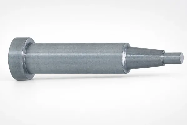
The slide must return fully before the mold closes. Springs return short slides. Limit switches verify the home position on large slides. A slide that returns 1 mm short flashes on the very next shot. The return mechanism is sized on the drawing, not at the press.
Locking the Slide During Injection
Injection pressure pushes the slide backward. The heel block locks the slide against the fixed half with a taper, typically 5 degrees of lock angle. The lock face carries the full cavity pressure, so it is machined flat and square. That face is a 0.005 mm tolerance job, inside DieStrike's mold size precision band.
Worn lock faces let the slide creep. Creep shows as flash at the side wall, typically 0.02-0.05 mm thick before it becomes visible. The check is a dial indicator reading at the slide nose during the shot. Any reading above 0.02 mm sends the mold back to the bench.
Lifter Angle Limits and Stroke Rules
Lifters handle internal undercuts by moving at an angle during ejection. The lifter rises with the ejector plate and slides sideways at the same time. The angle is the whole design. Too steep and the lifter binds. Too shallow and the stroke becomes too long for the ejector plate.
The 5-12 Degree Window
Practical lifter angles run 5-12 degrees. Below 5 degrees the horizontal travel per stroke is tiny. Above 12 degrees the lifter side-loads the ejector system and binds. The common working range for automotive lifters is 8-10 degrees, typical industry practice.
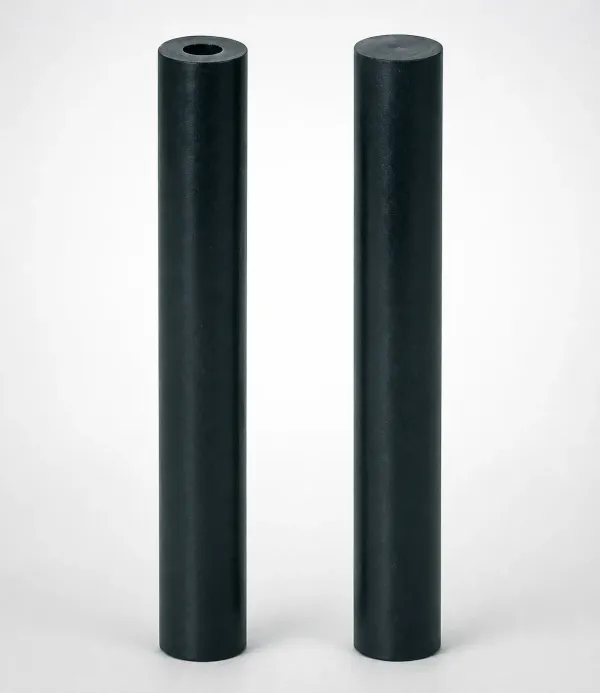
The horizontal travel equals the vertical ejector stroke times the tangent of the angle. A 10 mm ejector stroke at 10 degrees clears 1.76 mm of undercut. The same stroke at 12 degrees clears 2.13 mm. That 0.37 mm difference decides whether a snap hook releases cleanly or drags.
| Lifter Angle | Travel per 10 mm Lift (mm) | Typical Use |
|---|---|---|
| 5 degrees | 0.87 | Shallow hooks with long stroke available |
| 8 degrees | 1.41 | Common general purpose |
| 10 degrees | 1.76 | Most automotive lifters |
| 12 degrees | 2.13 | Maximum practical, tight stroke budgets |
| 15 degrees | 2.68 | Not recommended, binding risk |
← swipe to scroll →
Note: travel equals lift stroke times tan(angle), calculated values. The 15 degree row is shown as the rejection threshold.
When the required travel exceeds 2.13 mm per 10 mm of stroke, the lifter gets too steep. Switch to a side action or increase the ejector stroke. A 3 mm internal undercut at 12 degrees needs a 14.1 mm ejector stroke. If the ejector plate only travels 20 mm, the lifter consumes 70 percent of it.
Side Action Travel Calculations
Travel math is done once, on the drawing, and verified at T1. The formula is simple. Travel equals undercut depth plus 2-3 mm of clearance. The hard part is reading the real depth from the part model instead of the nominal dimension.
Reading Undercut Depth from the Model
Undercut depth is measured perpendicular to the pull direction, at the widest blocked section. A tapered hook has its maximum depth at the tip. A hole through a boss has depth equal to the hole width in the pull direction. Overlooking the tip width is the most common travel error in DFM reviews.

Add 0.5-1 mm of safety to the clearance for ejection variation and shrink. Ejector stroke varies with resin temperature and cycle time. A 2 mm clearance on paper can measure 1.5 mm in production. The safety margin is cheap on the drawing and expensive at the press.
| Part Feature | Undercut Depth (mm) | Clearance (mm) | Total Travel (mm) | Mechanism |
|---|---|---|---|---|
| Connector latch hook | 0.5 | 2.0 | 2.5 | Side action, spring return |
| Door trim clip hole | 1.5 | 2.5 | 4.0 | Side action, 20 degree angle pin |
| Headlamp bracket side hole | 6.0 | 3.0 | 9.0 | Hydraulic side action |
| Snap hook inside housing | 1.0 | 2.0 | 3.0 | Lifter at 10 degrees |
← swipe to scroll →
Note: total travel equals undercut depth plus clearance. The 2-3 mm clearance band is standard mold shop practice.
Example: Headlamp Bracket Side Hole
A headlamp bracket carries a 6 mm deep side hole for a mounting bolt. Travel is 6 plus 3 mm, so 9 mm. With a 20 degree angle pin, the vertical stroke is 9 divided by the tangent of 20 degrees, about 24.7 mm. That stroke is beyond a spring return, so the design uses a hydraulic cylinder.
The same 9 mm as a lifter would need a 42 mm ejector stroke at 12 degrees. That is taller than most ejector plates allow. The mechanism decision follows the travel number, not the preference. Each number is checked at T1 with the part released by hand.
Standard Parts and Steel for Side Actions
Side actions are built from standard parts wherever possible. Slide units, gibs, wear plates, angle pins, and springs are off-the-shelf catalog items. Standard parts cut build time and make future replacement predictable. DieStrike ships standard mold components, including undercut plates and side action components, in 3-7 days.
The steel plan splits the slide into a body and an insert. The slide body carries the motion and takes wear. The insert forms the part geometry and takes the heat. Common body steels run P20 or 718H at HRC 28-32. Inserts run H13 or SKD61 hardened to HRC 48-52, and DieStrike hardens cavity inserts to HRC 62 for automotive production volumes.
Wear Protection on Sliding Faces
Sliding faces run steel on steel at every shot. Wear plates and gibs give the slide a replaceable wear surface. Hardened wear plates at HRC 58-62 outlast the base steel by 5-10 times. Replacing a wear plate takes hours. Rebuilding a galled slide takes days.
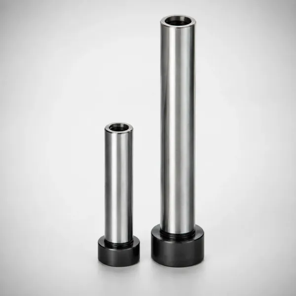
Lubrication is part of the design, not an afterthought. Grease grooves machined into the gib faces hold the lubricant. Automotive programs schedule re-lubrication every 5,000-10,000 shots, typical maintenance practice. A dry slide galls within 10,000-50,000 cycles, and a galling slide scrapes the part wall on every shot.
When to Redesign the Part Instead
The cheapest way to handle an undercut is to remove it from the drawing. A side action costs $3,000-$15,000. A draft change costs nothing in tooling and a few hours in CAD. The redesign review happens in DFM, before steel, while the part is still a model.
Re-Route the Draft
Faces that create undercuts can often take draft instead. A snap hook with 1 degree of draft on a 20 mm face moves 0.35 mm per side. That is enough to clear many latches without a mechanism. The functional check is the release force, which must still meet the assembly spec.
The rule of thumb is simple. If the undercut depth is 3 mm or less and the face can carry 1-2 degrees of draft, draft usually wins. The trade-off is a looser fit. Seals and gaskets need controlled gaps, so check the interface before re-routing draft on a sealing face.
Move the Parting Line
An undercut can move from one mold half to the other by shifting the parting line. A lip that locks in the fixed half becomes draftable in the moving half when the split moves 5-10 mm. The new split creates a step in the parting surface, which needs a careful seal-off.
The step adds a shut-off face that must seal at clamp tonnage. Shut-off faces get 1-3 degrees of draft toward the steel contact. Flash risk rises when the step is long. Balance the split against the added seal length, and confirm the whole geometry rule set in our how to design for moldability guide.
Open the Feature Instead of Closing It
A closed hole is an undercut. An open slot is not. A side mounting hole can become a U-shaped slot that opens to the parting line. A blind latch pocket can open to the part edge. The part loses a little stiffness and gains a much simpler mold.
Open features also vent better and eject cleaner. The change is a strength check, not a mold check. Run the FEA on the open feature at the same load case. If it passes, the mold saves a full mechanism and the program saves the side action budget.
Undercut Cost Drivers
Undercuts move cost through four channels. They are machining, standard parts, assembly, and tryout. Each channel scales with depth and position. The $3,000-$15,000 per side range is the total of all four, typical industry figures.
Where the Money Goes
The first channel is machining. A slide pocket removes steel, cuts gibs, and fits wear plates. The second is the standard part package. The third is skilled bench time for fitting. The fourth is tryout, where flash and galling get fixed. All four appear on the mold quote line by line.
| Cost Item | Typical Range | What It Covers |
|---|---|---|
| Slide body machining | $1,200-$5,000 per side | Steel removal, slide pocket, gibs, wear plates |
| Standard slide unit | $800-$2,500 per unit | Catalog slide, angle pin, springs, limit switch |
| Hardened insert and heat treatment | $600-$2,000 per insert | H13 or SKD61, HRC 48-62, EDM detail |
| Assembly and fitting | 8-24 hours | Skilled bench time, ±0.005 mm fitting |
| Tryout and debugging | +2-5 days | Flash fixes, galling fixes, travel verification |
← swipe to scroll →
Note: typical industry figures. DieStrike holds mold dimensions to ±0.005 mm and part geometry to ±0.002 mm under IATF 16949.
The second cost is mold base size. A deep side action needs base space for the slide and the cam. Every 25 mm of added base width raises the base cost by roughly 10-15 percent, typical industry figures. The base grows even when the part does not.
Delivery also stretches. A standard mold with no side actions runs 2-4 weeks at DieStrike. Adding one side action adds 1-2 weeks of machining and assembly. Programs should budget that lead time before the RFQ, not after. DieStrike builds production molds for TE Connectivity, Amphenol, Luxshare, and Dongshan Precision, where undercut-heavy housings are the norm.
Common Side Action Failure Modes
Side actions fail in predictable ways, and every failure is a mold book entry. Galling, flash, pin wear, and lifter binding cover most of them. Each has a number, a cause, and a fix. These are the checks our toolmakers run at T1 and at every 50,000-shot service interval.
Galling on Sliding Faces
Galling starts when sliding faces run dry or when the hardness differential is wrong. Steel on steel at the same hardness welds in micro spots. The fix is a wear plate at HRC 58-62 against a body at HRC 28-32. Galling usually shows within 10,000-50,000 cycles when the lubrication plan fails.
Flash at the Slide Wall
Flash appears at the side wall when the slide creeps under pressure. A lock face with 5 degrees of taper holds, and a worn one does not. Flash thickness of 0.02-0.05 mm is visible on a Class A surface. The fix is re-cutting the lock face or replacing the heel block, both sub-0.005 mm tolerance jobs.
Angle Pin Wear and Bending
Angle pins wear at the bushing when the cam angle climbs past 25 degrees. A bent pin shows as a slide that returns crooked. The check is the home position reading at the limit switch. Replace the pin and bushing as a set, and keep the return spring force written on the drawing.
Lifter Binding
Lifters bind when the angle passes 12 degrees or the clearance is too small. The symptom is a loud ejection and a part with drag marks. The clearance between the lifter and the core pocket runs 0.02-0.05 mm per side typical. Grease grooves and a polished bore keep the lifter moving.
Preventive checks cost less than repairs. A side action teardown at 50,000 shots replaces wear plates and pins before they fail. The mold book records every reading, and the next interval is set from the trend. DieStrike schedules this inspection into the maintenance plan for production automotive tools.
FAQ: Undercut Design
Q1. What is the maximum undercut depth a lifter can handle?
A lifter clears horizontal travel equal to the ejector stroke times the tangent of the angle. At the practical 12 degree limit, a 10 mm stroke clears 2.13 mm. Most automotive lifters handle 1-3 mm of undercut depth. Deeper features switch to side actions or hydraulic cylinders.
Q2. How much does a side action add to mold cost?
$3,000-$15,000 per side, typical industry figures, depending on travel, steel, and standard parts. A small spring-return slide with 2.5 mm of travel sits at the low end. A hydraulic assembly with 40 mm of travel sits at the high end. Delivery stretches by 1-2 weeks.
Q3. When should I redesign the part instead of adding a side action?
When the undercut is 3 mm or less and the face can carry 1-2 degrees of draft, redesign usually wins. Re-routing draft or moving the parting line costs nothing in tooling. Check the release force and the seal gaps before approving the change. DieStrike covers this in the 24-hour DFM review.
Q4. What clearance goes into side action travel?
Undercut depth plus 2-3 mm of clearance. A 4 mm deep feature gets 6-7 mm of travel. Add 0.5-1 mm of safety for ejection variation on high-volume tools. The number is verified at T1 by releasing the part by hand.
The Bottom Line
Undercuts decide mold cost, delivery, and long-term reliability. Each locked feature is a mechanism decision with a price tag from $3,000 to $15,000. Classify early, size the travel, and question every undercut before you tool it. That discipline keeps automotive programs on budget.
DieStrike builds automotive molds under IATF 16949 with 24-hour DFM feedback and 2-4 week injection mold lead times. Send us your part drawing and get an undercut-by-undercut cost review before you cut steel.
KEEP READING
Related Reading
5 Mold Cooling Channel Design Tips for Faster Cycles
Mold maker's 5 cooling channel design rules: channel-to-cavity distance 2-2.
Read articleArticle5 Shrinkage Compensation Rules for Mold Design
Shrinkage compensation decides mold accuracy. Five rules: material rates from 0.3% to 2.
Read articleArticle5 Ways to Reduce Mold Cost Without Cutting Quality
Five proven ways to reduce injection mold cost without cutting quality: DFM before quoting, right-sized cavity count,…
Read articleArticle7 Gate Design Best Practices for Balanced Filling
Mold maker's 7 gate design rules for balanced multi-cavity filling: gate depth 50-80% of wall thickness, land 0.5-1.
Read articleNEXT STEP
Ready to Start Your Mold?
Send us your element dimensions or part numbers — our team responds within 24 hours with pricing and lead time.

Written by
Ray ChanMold Buyer's Guide Author · Precision Mold Manufacturing Specialist. Ray helps global importers, distributors and OEMs source factory-direct molds and mold parts.