
5 Ejector Pin Installation Mistakes That Scrap Molds
Table of Contents
A single bent ejector pin can stop a 32-cavity mold in the middle of a production run. It can scrap 1,500 parts in one shift (typical). It can force a teardown that costs $3,000 to $15,000 in labor (typical) before a replacement pin arrives. Most of that damage is avoidable. The pin failed because of how it was installed, not because it wore out.
Ejector pins look simple. A hardened steel rod pushes a molded part off the core after every cycle. Yet pin installation errors are a top cause of mold downtime and early mold retirement. Five mistakes account for most ejector failures. Each one is measurable, preventable, and caught by a check that takes minutes.
The checks are cheap; the failures are not. A clearance error of 0.02 mm (typical) is invisible to the eye. It shows up as flash, sticking, or bent pins inside the first 10,000 cycles (typical). This article covers the five mistakes, the numbers that stop them, and how to verify the ejector system before the mold ever runs.
The Snapshot
- 0.01–0.03 mm (typical) per-side clearance between pin and hole keeps pins sliding without flash or sticking.
- 0.05–0.1 mm (typical) pin projection above the cavity surface clears the part without leaving ejector marks.
- HRC 58–62 (typical) pin hardness prevents galling; DieStrike pins run at HRC 62.
- Length-to-diameter ratios above 10:1 (typical) need center relief and guided support.
- Standard ejector pins ship from DieStrike in 3–7 days.
Mistake 1: Wrong Pin Diameter vs. Hole Clearance
The pin-to-hole fit decides everything downstream. Too tight, and the pin sticks, drags, and bends. Too loose, and melt flashes past the pin tip and forms a burr that tears the part on ejection. Both failures scrap parts and damage the mold.
What Goes Wrong
A pin with near-zero clearance grabs the hole wall under mold temperature. The ejector plate then has to push a stuck pin, which bends the pin and can bow the plate. A pin that is too loose lets resin flash around the tip at the cavity surface.

Flash around a pin is not cosmetic. The thin web of material welds to the pin, lifts the part off the core unevenly, and can pull the pin head from its retainer. On a 32-cavity automotive connector mold, one flashing pin stops the whole mold while the cavity is corrected.
The Numbers That Matter
For pins up to 6 mm diameter, 0.01 to 0.03 mm (typical) clearance per side is the working window. Below 0.005 mm (typical) per side, pins stick under heat. Above 0.05 mm (typical) per side, flash appears on pins that run unsupported against the cavity.
Larger pins take more clearance. Pins above 6 mm diameter commonly run 0.02 to 0.05 mm (typical) per side. Longer sliding lengths and higher mold temperatures close the gap during the cycle, so the running clearance shrinks.
Hole quality sets the real fit. A drilled hole with 0.02 mm (typical) ovality eats half the clearance budget. DieStrike machines ejector holes with roundness held to ±0.005 mm (standard).
How to Install Correctly
- Measure the pin OD at the top, middle, and bottom with a micrometer (0.001 mm resolution typical).
- Measure the hole diameter at both ends with a bore gauge (0.001 mm resolution typical).
- Confirm per-side clearance sits in the 0.01–0.03 mm (typical) window for the pin size.
- Check that pin and hole are free of chips, coating damage, and burrs before assembly.
- Push each pin by hand. It should slide with light, even resistance and drop freely when tilted.
How to Verify
Fit a dial test indicator to the ejector plate and pull each pin out 2 mm. Readings that jump or stick indicate a tight spot, an oval hole, or a bent pin. Rework the hole before first shot, not after 10,000 cycles (typical).
Mistake 2: Misaligned Pins and Wrong Pin Length
Ejector pins move in a straight line. If the pin is not square to the plate, or the length is wrong, that line is broken. The result is uneven ejection, bent pins, and parts that deform when they leave the mold.
What Goes Wrong
A pin that is shorter than its neighbor pushes nothing. The part stays on the core at that spot and drags across the remaining pins as they extend. A pin that is too long pushes hard at one point and creates a sink mark or a visible ejector mark on the part.
Misalignment works the same way. When the pin axis does not match the hole axis in the cavity, the pin bends under load. A 2 mm pin bent by 0.1 mm (typical) at the tip takes a permanent set after enough cycles.
Bending is not the only cost. Uneven ejection tilts the part, and a tilted part can wipe out fine cavity details on the way off the core. Detail damage on a connector mold means steel welding, re-cutting, or a new insert.
The Numbers That Matter
Pin projection above the cavity surface should be 0.05 to 0.1 mm (typical) on flat surfaces. Deep ribs and bosses often need 0.1 to 0.3 mm (typical) to clear the feature. The same value must hold across all pins in the set.
Pin length tolerance is part of the fix. Lengths held to ±0.02 mm (typical) keep projection uniform across the plate. Plate flatness under 0.01 mm per 100 mm (typical) keeps every pin tip on the same plane.
Ejection force is part of the length check. Long pins under 0.5 N of ejection force each (typical) bend before they push. Add support or shorten the unsupported span when force exceeds the pin's buckling limit.
How to Install Correctly
- Seat the ejector plate on the same datum used in machining.
- Ream pin holes in the plate and the cavity with the same tool setup, so axes stay aligned.
- Drop each pin in and confirm the head seats fully in its pocket.
- Check that stepped pins land on their shoulder, not on the plate edge.
- Set pin length so projection lands in the 0.05–0.1 mm (typical) window.
How to Verify
Run the ejector system by hand before the mold goes to the press. Pins should extend together, return together, and show no tilt. Then measure projection on a height gauge and compare pin to pin across the set.

Measure the gap between each pin tip and the cavity surface with a feeler gauge on a closed mold. Variations above 0.03 mm (typical) between pins point to length or seating errors. Correct them before the mold ships.
Mistake 3: Hardness Mismatch or Wrong Pin Material
Pins slide against the ejector plate and sometimes the cavity steel thousands of times per shift. If the pin is softer than the surface it slides on, it wears, galls, and seizes. Material choice decides how long that sliding lasts.
What Goes Wrong
Galling is cold welding. Two steel surfaces under high contact pressure and temperature weld at microscopic peaks, tear, and weld again. A soft pin against a hard plate wears the pin; a soft plate wears the hole.
Once a pin starts to gall, it does not self-heal. The damaged surface drags harder on every cycle, ejection force climbs, and the pin eventually seizes. A seized pin bends or shears the first time the ejector plate pushes with full force.
The Numbers That Matter
Standard ejector pins run HRC 58 to 62 (typical), most often nitrided or through-hardened. DieStrike pins are specified at HRC 62. A 5 to 10 HRC difference (typical) between pin and plate is normal. It keeps wear on the pin, which is the replaceable part.
Material matters more at high mold temperatures. LSR and high-temperature engineering resins push mold steel past 150°C (typical), where unlubricated steel-on-steel galling accelerates. Nitrided pins hold a hard surface layer through those cycles.
How to Install Correctly
- Confirm the pin material and hardness on the certificate before assembly.
- Spot-check hardness with a portable tester (HRC scale) when certificates are missing.
- Match pin hardness to the operating temperature of the mold, not the shop average.
- Use nitrided pins for high-temperature and LSR molds.
- Never mix pins of different hardness in one ejector set.
How to Verify
After the first 500 cycles (typical), pull two pins and inspect the sliding surface. Bright, uniform contact is good. Streaks, scoring, or pickup mean the hardness pair or the clearance is wrong.
Log the results on the mold card. The next teardown reads the history instead of guessing.
Mistake 4: Skipping Lubrication at the Pin-to-Plate Interface
Ejector pins are a sliding system, and sliding systems need lubrication. Skipping it raises friction, wears the pin, and drives ejection force up. Using the wrong lubricant does the same damage in a different way.
What Goes Wrong
Dry steel-on-steel sliding has a coefficient of friction around 0.5 (typical). A lubricated interface drops to about 0.1 (typical). On a mold with 32 pins, that difference is real: ejection force can climb 2 to 3 times (typical) when lubrication is missing.
Higher ejection force does not stop at the part. It bends pins, stretches retainer screws, and can lift the ejector plate off its guides. The mold then runs with the plate out of square, and every downstream check drifts.
How to Lubricate Correctly
Apply a thin film of molybdenum disulfide (MoS2) grease to the pin's sliding section at assembly. MoS2 grease stays stable to about 350°C (typical), which covers most mold operating ranges.
Re-lubricate on a schedule. Every 50,000 to 100,000 cycles (typical) is a common interval for standard molds. High-speed molds with 30-second cycles reach that interval in days, so schedule by cycles, not by calendar.
Keep lubricant off the pin tip. Grease on the cavity face catches flash, burns, and turns into carbon that scores the cavity. Wipe the tip before closing the mold.
How to Verify
Watch ejector force on the machine's first cycles. A smooth, stable reading at the same value cycle after cycle means the system is running wet and true. A climbing reading means friction is building somewhere.
Inspect the grease film at the next scheduled maintenance. A dry pin at 100,000 cycles (typical) is a scheduled failure you can see coming.
Mistake 5: Assembly Errors , Spacing, Venting, and Center Relief
The final mistakes happen at assembly, when pins are placed, spaced, and finished. Three errors show up most: wrong pin-to-pin spacing, blocked venting, and long pins without center relief.
Wrong Pin-to-Pin Spacing
Pins too close together leave a thin steel wall between holes. That wall is a stress riser in the core, and it cracks under ejection load. Pins too far apart leave unsupported part areas that stick and deform.
Keep at least 1.5 times the pin diameter (typical) of steel between adjacent hole walls. A 2 mm pin needs 3 mm of core steel between holes. Below that, the core web is the weak link, not the pin.
Blocked Venting at the Pin
Pin holes often double as vents. Trapped gas at the pin location burns the part, causes short shots, and slows the cycle while you chase the cause. A blocked pin vent is invisible from the cavity side.
Verify gas paths before assembly. Confirm the pin hole connects to an atmosphere vent, and that nothing , grease, chips, sealant , blocks the route. On high-cavitation molds, pin vents are part of the venting balance.
Long Pins Without Center Relief
A long pin sliding on its full length drags over the whole bore. Friction, heat, and galling all grow with sliding length. The fix is center relief: a reduced diameter section in the middle of the pin.
Cut the middle of the pin 0.5 to 1.0 mm (typical) smaller than the OD. Keep 15 to 20 mm (typical) of full diameter at the head and at the tip for guidance. Length-to-diameter ratios above 10:1 (typical) should not run without relief.
How to Verify
Slide each long pin through the plate by hand before assembly. It should run with resistance only at the guided ends. If the middle section binds, the relief is missing or the bore is out of round.
Ejector Pin Types: Straight, Stepped, and Shouldered
The three standard pin types exist for a reason. Each changes how the pin is guided, how it is retained, and where it fails. Picking the right type removes whole categories of installation mistakes.
Straight Pins
A straight pin has one diameter from head to tip. It is the least expensive type and works well where the pin is short and ejection loads are low. The full pin length slides, so friction scales with length.
Stepped Pins
A stepped pin reduces the sliding diameter above the plate. Less contact area means less friction, less heat, and less galling. Stepped pins suit deep cores where a straight pin would drag over too much surface.
Shouldered Pins
A shouldered pin has an enlarged head that a retainer plate locks in place. It resists pull-out and spreads ejection load over a wider area. Use shouldered pins in thin ejector plates and for small diameters under high force.
Straight pins cover most shallow cores. Stepped pins carry deep cores. Shouldered pins handle thin plates and high force. The five mistakes above map onto these choices: clearance and lubrication affect all three types, alignment most of all.
Choosing the right pin shape is its own decision. The selection logic for connector molds, including force, spacing, and clearance, is covered in how to select ejector pins for automotive connector molds.
How to Verify an Ejector System Before First Shot
Verification is not optional. It takes minutes and catches the failures that scrap molds. DieStrike runs the same checks on every mold before the first shot.
Check Projection and Flushness
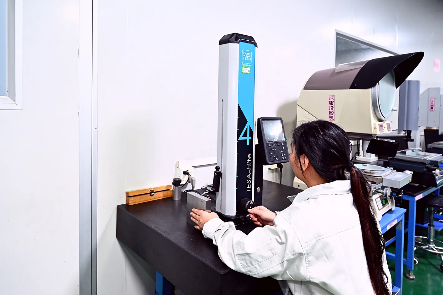
Measure pin projection on a height gauge with the plate fully extended. Target 0.05 to 0.1 mm (typical) on flat surfaces, uniform across the set. Measure plate flushness with the pins seated; high pins and low pins both cause defects.
A pin sitting 0.05 mm (typical) high on a thin-wall connector cavity can push a witness line into the visible face. A pin sitting low leaves the part stuck. Both are caught in the same 10-minute check.
Check Position With the CMM
Compare pin positions to the CAD model. Pin location held to ±0.01 mm (typical) keeps ejection balanced across the cavity. DieStrike runs these checks on Zeiss CMMs with ±0.005 mm (standard) positioning; precision work targets ±0.002 mm.
Check the First Cycles
Hand-cycle the ejector system before the mold reaches the press. Pins extend together, return together, and ride freely. Then watch ejection force on the first 50 production cycles (typical) for drift.
Record the machine's ejector pressure at cycle 10 and again at cycle 50. A stable value within 5% (typical) means the system is settled. Rising pressure means the pins are wearing in wrong.
Ejector Pin Installation Mistakes: Summary Table
The table below maps each mistake to its symptom and the fix that prevents it. Use it as an assembly checklist, not a reference.
| Mistake | Symptom | Fix |
|---|---|---|
| Wrong pin diameter vs. hole clearance | Sticking, bent pins, flash at the pin tip | Hold 0.01–0.03 mm (typical) per-side clearance |
| Misaligned pins or wrong length | Uneven ejection, bent pins, ejector marks | Align to the plate datum; verify 0.05–0.1 mm (typical) projection |
| Hardness mismatch or wrong material | Galling, wear, seized pins | Use HRC 58–62 (typical) pins; nitrided for high-temperature molds |
| Skipped or wrong lubrication | Friction, galling, rising ejection force | MoS2 grease (typical) at assembly; re-lube every 50,000–100,000 cycles (typical) |
| Assembly errors , spacing, venting, center relief | Core cracking, burn marks, bent long pins | Keep 1.5× pin diameter (typical) between holes; cut relief above 10:1 L/D (typical) |
← swipe to scroll →
FAQ: Ejector Pin Installation
What clearance should an ejector pin have in its hole?
Pins up to 6 mm diameter run 0.01 to 0.03 mm (typical) clearance per side. Pins above 6 mm run 0.02 to 0.05 mm (typical). Below 0.005 mm (typical) pins stick; above 0.05 mm (typical) flash appears. Measure both the pin OD and the hole before assembly.
How far should an ejector pin project above the cavity surface?
0.05 to 0.1 mm (typical) on flat surfaces. Deep ribs and bosses need 0.1 to 0.3 mm (typical) to clear the feature. Less leaves the part stuck on the core; more creates visible ejector marks and can deform thin walls.
What hardness should ejector pins be?
HRC 58 to 62 (typical) for standard pins. DieStrike specifies HRC 62. The pin should run 5 to 10 HRC (typical) harder than the plate so wear stays on the replaceable part. Nitrided pins add a hard surface layer for high-temperature molds.
Why do ejector pins gall, and how do you stop it?
Galling is cold welding between sliding steel surfaces under pressure and temperature. It starts when clearance is tight, hardness is mismatched, or lubrication is missing. The fix is a 0.01–0.03 mm (typical) clearance and a pin at HRC 58–62 (typical). Add MoS2 grease at assembly and center relief on pins above 10:1 L/D (typical).
When should you use shouldered pins instead of straight pins?
Use shouldered pins in thin ejector plates, for small diameters, and where ejection force is high. The enlarged head stops pull-out and spreads load. Straight pins suit short pins with low loads, where the full length can slide freely.
The Bottom Line
Ejector pin installation is a repeatable process, not guesswork. Hold the clearance, verify the projection, check the hardness, lubricate the interface, and respect the length-to-diameter limit. Every check is measured in tenths of a millimeter, and every check prevents a teardown.
The numbers are small, but the consequences are large. A 0.02 mm (typical) clearance error can cost a $3,000–$15,000 (typical) repair and a week of downtime. A working ejector system, by contrast, runs tens of thousands of cycles on the pins that shipped with the mold.
When a pin does fail, the repair sequence matters. Read how to replace a broken ejector pin before you pull the mold, and keep the fix inside the numbers above. If you are specifying pins for a new project, start from the DieStrike ejector pins range. Match the part to the mold, not the catalog.
NEXT STEP
Ready to Start Your Mold?
Send us your element dimensions or part numbers — our team responds within 24 hours with pricing and lead time.

Written by
Ray ChanMold Buyer's Guide Author · Precision Mold Manufacturing Specialist. Ray helps global importers, distributors and OEMs source factory-direct molds and mold parts.