
How to Set Up Die Protection Sensors in Progressive Dies
Table of Contents
A missed slug in a 400 t progressive die stops production for weeks, not minutes. The slug lodges on the die block at 600 strokes per minute. The next stroke drives a hardened punch into it and takes the die block, two stations and a pilot with it. Die repair on that scale runs 2 to 6 weeks, and press downtime costs 80 to 200 dollars an hour. Die protection sensors exist to catch that slug inside one stroke, and this guide covers how to place, wire, time and prove them.
Everything below covers the sensor layer only: family selection, placement, timing, fail-safe wiring, commissioning and per-part records.
The Snapshot
- One stroke at 600 SPM is 100 ms. Sensor response of 5 to 20 ms, a PLC scan of 10 to 15 ms and 30 to 60 ms of clutch and brake travel all have to fit inside that window.
- Five sensor families cover the die. Proximity for strip presence, photoelectric for part-out and short feed, air or electric gap sensors for slugs and double blanks, a tonnage monitor for the load signature, and mechanical misfeed probes.
- Placement is geometry, not preference. Sense the strip after the feeder and before the first pilot engagement, and put the part-out window at least 20 mm ahead of the scrap cutter.
- Prove it on a deliberately short-fed strip. A 100 percent detection test means a trip on every one of 20 to 50 consecutive short feeds, with zero misses and zero false stops on good material.
What One Die Crash Costs
A die crash is rarely a single punch that breaks. The first hit damages a punch tip, a pilot or a stripper insert. The next hits transfer that load into the die block, the guide posts and the press bed. At 600 strokes per minute an operator has 100 ms per stroke to react, which is not a workable margin. The press will complete 10 strokes before a hand reaches the stop button.
Typical crash damage splits into four repair tickets. Punches and pilots bend at the shank or shear at the head. Die block sections crack at a thin wall or a sharp corner. Stripper plates bow and lose parallelism by 0.05 to 0.2 mm. Guide posts and ball cages pick up the sideload that the punch could not carry.

Only the first two of those tickets are quick repairs. A cracked block section means re-cutting a plate and re-hardening to HRC 58 to 62. It then goes back on the jig grinder to plus or minus 0.005 mm.
The schedule number is the one that hurts. Die repair on a crashed progressive tool runs 2 to 6 weeks at a die shop. That assumes the shop has open capacity that month. Add press downtime at 80 to 200 dollars an hour across two shifts, plus expedited freight for replacement coil already in transit. A single crash on a 400 t line commonly lands between 25,000 and 120,000 dollars before the next good part is made.
Every crash has a trigger, and the triggers repeat. A short feed leaves a station with no material to cut. A slug pulled up on a punch drops onto the die block two strokes later. A double blank from the destacker doubles the cutting load. A coil end or a butt weld buckles into the tooling at the first station.
A slipping feed roll jams the strip against a pilot. A press knows ram position and, on some machines, tonnage at the connections. None of those six events is visible to the press control.
The Five Sensor Families in a Progressive Die
Five families cover almost every protection point on a progressive die. Each one watches a different failure mode, and a die running 500 strokes per minute usually carries three or four of them at once.
The table below is the selection map. Response times are sensor-level figures, and the full loop adds the PLC scan plus the clutch and brake, which the next section quantifies.
| Family | What it detects | Typical hardware | Response and setting notes |
|---|---|---|---|
| Proximity | Strip presence, strip end, hole presence, station 1 material | M12 or M18 inductive barrel, 2 to 8 mm sensing distance | 1 to 5 ms response, 24 V DC PNP, gap set at 1.5 to 3 mm |
| Photoelectric | Part-out, short feed, strip present in a wide window | Through-beam pair or a fork sensor across a 300 to 600 mm die window | 0.5 to 5 ms response, needs 8 hour lens cleaning on oily strip |
| Air gap or electric slug sensor | A slug or a pierced part left in a hole, slug pull | Air gap nozzle at 0.1 to 0.3 bar, or a small inductive ring head | 5 to 20 ms response, 0.05 bar pressure drift triggers a false trip |
| Tonnage monitor | Load signature per stroke, chipped punch, dulling, missing cut | Strain links on the uprights or the connections, sampled at 1,000 to 5,000 Hz | Warning at plus or minus 5 percent, stop at plus or minus 10 percent of baseline |
| Mechanical misfeed probe | Missing pilot hole, misindexed strip, misfeed | Spring-loaded probe with 2 to 4 mm travel into a plunger switch | No amplifier, no calibration drift, 2 million stroke life typical |
← swipe to scroll →
Table note: response bands are typical sensor datasheet values at 24 V DC. Confirm the real loop time on the press with a stroke timer or the controller timestamp before release.
Proximity sensing is the workhorse for strip presence. A 12 mm or 18 mm inductive barrel detects the strip edge or a pierced hole. It returns a discrete signal in 1 to 5 ms. Nominal sensing distance on mild steel runs 4 to 8 mm for an M18 body, and the real distance halves on stainless or aluminium. Mount the sensor on a shimmed bracket so the 1.5 to 3 mm gap resets without machining.

Photoelectric sensing handles part-out and short feed because it can see a gap where no metal exists. A through-beam pair across the die responds in 0.5 to 5 ms. It ignores strip grade and thickness, so the same head works on a 0.1 mm terminal strip and a 3 mm bracket.
Slug detection is the hardest point in the die. An air gap sensor fed at 0.1 to 0.3 bar reads a pressure change when a slug sits in a pierced hole. An inductive ring head does the same job on a fixed hole with no air supply. A double blank sensor sits in the feeder, where it rejects two sheets before they reach the tooling.
A tonnage monitor is not a discrete sensor and cannot stop a crash in progress. It records the load signature of every stroke and catches the slow failures. They are a chipped punch shaving 3 to 8 percent of peak load, a die dulling across 50,000 strokes, or a station that stops cutting.
Mechanical misfeed probes are the oldest family and still the most dependable above 600 SPM. A spring-loaded probe rides in a pierced hole. A missing hole lets the probe travel 2 to 4 mm into a normally closed plunger switch. There is no amplifier and no calibration drift to explain to a night shift.
Timing Math: Sensor, PLC and Clutch at 600 SPM
Timing decides whether a sensor protects the die or only reports the crash afterwards. A stop command that lands after bottom dead center has already done its damage.
Convert the stroke rate to milliseconds first. At 600 strokes per minute every stroke lasts 100 ms. At 400 SPM it lasts 150 ms, and at 1,200 SPM, a normal rate for a terminal die, it lasts 50 ms. Those windows are the entire budget for detecting a fault, processing it and stopping the slide.
The budget inside one stroke breaks into four parts. Sensor response runs 0.5 to 20 ms depending on the family. A standard PLC scan adds 5 to 15 ms of latency, while a dedicated high-speed module checks an input in 1 to 2 ms. Output and valve response adds another 5 to 15 ms.
The clutch and brake on a mechanical press need 30 to 60 ms to bring the slide down from full speed. A servo press with a holding brake needs only 10 to 25 ms, which is the main reason high-speed dies are moving to servo drives.
| Press speed | Time per stroke | Sensor plus PLC | Clutch and brake | What the window allows |
|---|---|---|---|---|
| 200 SPM | 300 ms | 5 to 30 ms | 30 to 60 ms | In-stroke stop with over 200 ms of travel margin |
| 400 SPM | 150 ms | 5 to 30 ms | 30 to 60 ms | In-stroke stop on most mechanical presses |
| 600 SPM | 100 ms | 20 to 35 ms | 50 to 60 ms | Top stop on mechanical presses, in-stroke stop on servo |
| 800 SPM | 75 ms | 20 to 35 ms | 20 to 40 ms | Servo only for an in-stroke stop, sense 2 stations upstream |
| 1,200 SPM | 50 ms | 21 to 37 ms | 10 to 25 ms | Two-stroke upstream detection is mandatory |
← swipe to scroll →
Table note: loop times are typical bands for a 24 V DC sensor into a standard PLC or a dedicated die protection controller. Measure the real stop time on the press at production speed and keep the printout in the die file.
Add the detection and stop numbers and a mechanical press carries a 45 to 110 ms loop. A 20 ms sensor plus a 15 ms PLC scan plus a 50 ms clutch and brake consumes 85 ms of a 100 ms stroke. The remaining 15 ms of slide travel is what stands between a good die and a re-cut die block. A servo press clears the same check in 25 to 45 ms and keeps 55 ms of margin.
Where the loop does not fit, move the sensor upstream rather than buying a faster controller. A well-planned die checks the strip at the feed entry and again after the last piercing station. At 600 SPM a slug check placed three stations upstream of the tooling it protects turns a 100 ms window into a 300 ms window.
Process Protection Is Not a Safety Function
Die protection and machine safety share a cabinet, and they must never share a loop. Die protection protects the tool and the schedule. Machine safety protects a person from the slide, and a person is not a line item on a repair ticket.
Safety functions are designed to ISO 13849-1 and its performance levels. A press safety loop typically targets Category 3 architecture at Performance Level d. That means redundant channels, cross monitoring and a PFHd of 10 to the minus 7 to 10 to the minus 6 per hour. Interlocked guards, light curtains at 14 to 30 mm resolution and certified safety relays sit inside that loop.
A die protection input is normally single channel, non-redundant and self-declared. A proximity sensor that trips when the strip is missing is a process device at roughly PL a or PL b by construction. Wiring it into the safety loop would drag that loop down to the lowest architecture in the chain. That is a compliance failure and a real risk to the operator.
Keep the two systems physically and electrically separate. Use a separate 24 V DC supply, separate terminal blocks, a separate relay or input card, and a separate wire colour. Document the die protection channels as process functions in the drawing set and label them that way at the panel. Run the risk assessment to ISO 12100 and confirm the guarding to ISO 16092-1 for presses. Do that on its own schedule, not as part of a sensor upgrade.
A die protection trip is a process event, not a nuisance. After a trip the tool has to be opened and inspected before the press restarts. Resetting into an uncleared fault turns a 900 dollar punch into a 40,000 dollar die repair.
Placement Rules for Every Sensor Position
Placement follows the material flow, and each position carries a geometric rule.
Sense the strip after the feed rolls and before the first pilot engagement. The feeder is where a short feed or a slipping roll originates, and the pilot is where a misindexed strip does its damage. A proximity sensor 30 to 50 mm after the last feed roll catches the strip edge while a full stroke of margin is still available.
Put the part-out window at least 20 mm ahead of the scrap cutter. A part-out sensor confirms that the finished part left the strip before the cutter trims the carrier. Twenty millimetres of strip is roughly one and a half progressions on a 12 mm pitch die. That distance is what keeps a hung part from being cut in half and jamming the chute.
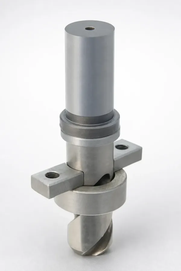
Slug sensors belong at the piercing station that creates the slug, aimed along the slug fall path. Mount the air nozzle so a released slug drops clear of the die block and never lands on a sensing face. A slug resting on the sensor face reads as a permanent fault and stops the press on the next stroke.
Double blank sensors sit upstream of the tooling, in the destacker or the feeder. A magnet pair in the feeder detects two sheets stacked within 0.5 mm. The stop command lands before the first station takes a doubled load. On a 1.2 mm strip a doubled blank nearly doubles the cutting load, which a tonnage monitor also catches.
Mount strain links or load cells as the monitor maker specifies, usually on the uprights or the connections. A four-channel monitor sets a separate warning band per station, and that per-station baseline is what makes a 5 percent load change mean something.
Two mechanical rules apply to every sensor bracket. Bracket plate thickness of 6 mm or more keeps a photoelectric head from vibrating out of alignment over 100,000 strokes. Never mount a sensor on a stripper plate or any spring-loaded member. That plate moves 15 to 30 mm on every stroke, and the setting will not survive a shift.
Wiring into the Press Control with Fail-Safe Loops
Wiring decides whether a sensor still protects the die after a cable breaks. A loop that reads safe with the sensor unplugged will eventually let a crash through.
Wire every channel as a normally closed fail-safe loop. The sensor conducts while the condition is good and opens on a fault, a broken wire or a lost 24 V supply. An inverted normally open contact fails the wrong way, because a cut cable looks exactly like a good part.
Use 24 V DC PNP sensors with solid-state outputs rated for the loop current. Keep leakage under 0.5 mA so a PLC input does not read a high while the sensor is off. Series the channels into the die protection relay coil. Where the controller supports it, give each channel its own high-speed input. That reports the tripped sensor in under a second.

Run shielded cable with the drain grounded at the panel end only. Never share a conduit with servo drive or variable frequency drive output, because induced noise trips a 24 V input at random. Where a die is swapped often, terminate the field wiring in a die-mounted junction box with an M23 or a Harting connector.
Keep the die protection loop on separate terminals, colours and relays from the safety loop. Put the stop contact in series with the press stop circuit and label the terminals DP1 to DP8.
Commissioning with a 100 Percent Detection Test
Commissioning is where most die protection systems are accepted without being proven. A sensor that has never seen the fault it detects is a decoration on a bracket.
Test with a deliberately short-fed strip rather than a hand or a screwdriver. Feed the strip 5 to 15 mm short of the pilot, which is a realistic feed error and the exact event the sensor exists for. Trip it 20 to 50 consecutive times and count the stops. A 100 percent detection test means zero misses at production speed. The feeder settings that prevent a short feed belong to the strip feed accuracy guide.
Repeat the test for every protection point. Pull a dummy slug onto the die block and confirm the stop on the next stroke. Remove a part from the part-out window and confirm the trip before the scrap cutter. Slide a second blank into the destacker and confirm the rejection. Lift a probe out of a pierced hole to confirm the misfeed stop.
Run the sequence at 200 SPM, at 400 SPM and at the production rate. Stop time grows with speed, so a system that holds at 400 SPM can lose the race at 800 SPM. Jogging the press into a fault must be impossible while the fault is present.
Capture the tonnage baseline in the same trial. Record 50 good strokes at production speed and store the mean peak load per channel. Set a warning band at plus or minus 5 percent and a stop band at plus or minus 10 percent.
A new tool from a stamping die manufacturing program is commissioned the same way, before handover to production rather than after the first crash.
False Trip Debugging: Light, Oil Mist and Gap
A false trip is more damaging than it looks. Two nuisance stops in one shift are enough for an operator to reach for the bypass key, and a bypassed channel protects nothing.
Start with the photoelectric window. Oil mist films a lens in 4 to 8 hours. Signal margin falls from 100 percent to under 30 percent before the first false trip appears. Add a lens clean and a signal strength reading to the shift checklist.
Check the mechanical gap next. A proximity sensor set at 1.5 to 3 mm drifts when a bracket bolt relaxes. On a 400 t press, 10,000 strokes move a 6 mm bracket by 0.2 to 0.5 mm. Re-torque, re-shim and mark the setting with paint.
Look for material sitting on the sensor. A slug on an air nozzle, a shaving in a probe hole or scrap on a part-out window all read as a permanent fault. Those trips are real rather than false, and they belong in the end-of-coil die clean.
Read the tonnage trace last. A load change inside the 5 percent warning band with no other symptom usually points at strip hardness variation or a coil weld. Widen the band only after you confirm the die with a punch clearance check.
Per-Part-Number Records and Settings Control
Every setting on a protected die is a number a future shift will need. A die with its sensor positions, gaps, cam windows and load baselines written down re-sets in 20 minutes at another plant. A die without them carries a two hour setup and a crash risk at every changeover.
Record six fields per sensor, on a die card and in the machine file. They are the model and channel number, the feature it watches, and the measured gap in millimetres. They also carry the cam window in crank degrees, the trip threshold, and the date of the last change with a signature. Keep the card in a pocket on the die plate. The sensor positions belong on the same drawing as the station sequence in the progressive die layout.
Put the die protection parameters behind a key switch or a level 2 password and log every change. An operator who can clear a trip by editing a cam window will do it at 3 a.m. on a night shift.
Re-run the detection test at every regrind, because a sharpening pass moves the punch height, the strip path and sometimes the sensor gap. The punch grades and hardness that set the sharpening interval are covered in the stamping die steel guide.
The Bottom Line
Die protection is a small system with a large payback. It comes down to five sensor families, a strip check after the feeder, and a loop that fits inside one stroke. Die repair at 2 to 6 weeks and downtime at 80 to 200 dollars an hour justify the hardware.
Prove the system on a deliberately short-fed strip before release, then log every sensor position, gap, cam window and load baseline on a die card. Keep the process loop and the safety loop separate, and re-run the detection test after every regrind.
DieStrike builds progressive dies and precision tooling to IATF 16949 across 120+ machines. Mold tolerance holds at ±0.005 mm, and at ±0.002 mm on EDM and jig grinding, with cavity steel heat treated to HRC 62 max. Standard components ship in 3 to 7 days and tool lead time runs 2 to 5 weeks. Tier-1 programs include TE, Amphenol, Luxshare and Dongshan.
KEEP READING
Related Reading
How to Design a Progressive Die Layout
Station sequence, pilot placement and the scrap web rules that decide whether a die runs at 400 SPM.
Read articleArticleStrip Feed Accuracy in Stamping
Feeder settings, loop control and the pilot engagement numbers that keep a 0.2 mm progression honest.
Read articleArticleStamping Die Steel Selection
Punch and die block grades, hardness windows and the coating choice for high stroke counts.
Read articleServiceStamping Die Manufacturing
IATF 16949 progressive die building with sensor integration and 2 to 5 week lead times.
Read articleNEXT STEP
Ready to Start Your Mold?
Send us your element dimensions or part numbers — our team responds within 24 hours with pricing and lead time.

Written by
Ray ChanMold Buyer's Guide Author · Precision Mold Manufacturing Specialist. Ray helps global importers, distributors and OEMs source factory-direct molds and mold parts.