
How to Maintain Punch Clearance in Progressive Dies
Table of Contents
A 14-station progressive die on a connector terminal line stopped at 09:40 after 412,000 strokes without a clearance check. The station 7 punch was cutting a 0.09 mm burr on a 0.6 mm strip. The slug pulled up with the punch, wedged under the stripper, and the next stroke drove the punch through a two-layer stack. The bill was eight hours of line time at $150-$300 per hour, about $900 in replacement punch and die button. A 25,000-piece batch failed the burr gauge.
Punch clearance is the gap between the punch side and the die opening wall, quoted per side. It decides where the sheet fractures and how high the burr grows. It decides how fast the edges wear and whether the slug stays in the die or rides up with the punch. The gap changes with every stroke. It is the cheapest value in the die to measure and the most expensive to ignore.
This guide covers what clearance should be, how it drifts, how to measure it, when to regrind, and what to replace. The numbers are typical industry figures for progressive die stamping. Verify each one against your material certificate, your part drawing, and your tryout record.
The Snapshot
- Per-side clearance for steel runs 5-10% of stock thickness. The die opening equals punch OD plus twice the per-side gap.
- Burr height is the working trigger. Regrind when burr exceeds 5-10% of material thickness, typically 0.05-0.08 mm on precision parts.
- A new cutting edge holds under 0.013 mm edge radius. An edge at 0.05-0.1 mm means a regrind is due.
- One sharpening removes 0.05-0.15 mm of face stock. A punch with 5-8 mm of grindable length survives 30-80 regrinds.
- Measure punch OD and die button ID to 0.001 mm every 100,000-200,000 strokes. That turns clearance from opinion into a trend line.
What Punch Clearance Is
Clearance is the air gap between the punch and the die opening at the moment of cutting. It is quoted per side, and the total gap across the opening is twice the per-side value. The die opening is machined as punch OD plus two times the per-side clearance. A Ø6.00 mm punch with 0.07 mm per-side clearance needs a Ø6.14 mm die opening.
The gap controls the fracture. The punch compresses the sheet, and the material shears from both edges toward the middle. At correct clearance on steel, the sheared band holds about one-third burnish and two-thirds fracture zone. The punch penetrates 30-40% of the stock thickness before fracture starts, typical for mild steel.
Too little clearance makes the edges collide before fracture completes. Cutting force rises 30-50%, edges wear faster, and galling appears on the punch side. Burr forms on the die side of the part, and slugs jam in the opening.
Too much clearance tilts the fracture plane. Rollover grows past the normal 5-10% of thickness, and burr forms on the punch side. The part edge distorts, and the die wall wears into a taper.
Fine blanking is the deliberate exception. It runs 0.5-1% per side with a V-ring impingement, which produces a near-full sheared surface instead of a fracture zone.
Clearance by Material
Material grade sets the starting clearance because tensile strength and ductility decide how the sheet fractures. Softer, ductile materials cut clean at low clearance. High-tensile and work-hardening grades need more room. The table below gives typical per-side values as a percentage of stock thickness.
| Material | Per-Side Clearance (% of stock) | Example: 1.0 mm Stock | Cutting Note |
|---|---|---|---|
| Mild steel (SPCC, DC01) | 6-8% | 0.06-0.08 mm | Balanced burnish and fracture zones |
| High-carbon steel (45, 65Mn) | 8-10% | 0.08-0.10 mm | Higher tensile strength, cleaner fracture |
| Stainless steel (304, 430) | 10-15% | 0.10-0.15 mm | Work-hardens; tight clearance causes pickup |
| Aluminum (5052, 6061) | 5-6% | 0.05-0.06 mm | Soft, low force, fine burr control |
| Copper and brass | 5-7% | 0.05-0.07 mm | Ductile; keep clearance at the low end |
| Fine blanking (any steel) | 0.5-1% | 0.005-0.01 mm | V-ring impingement, near-zero fracture |
← swipe to scroll →
Table: typical industry figures; verify against your program.
Worked example: a Ø6.00 mm punch cutting 1.5 mm mild steel at 7% per side needs 0.105 mm per side. The die button ID becomes Ø6.21 mm. On 304 stainless at 12% per side, the same punch needs Ø6.36 mm. Reusing the mild steel button for stainless adds 0.03 mm of clearance per side, which is enough to double the burr.
Stainless is the common failure point. It work-hardens at the cut zone, so tight clearance creates pickup on the punch and a torn edge on the part. If a die has run mild steel for years and the program switches to stainless, re-verify every station before the first production run.
Values above are typical industry figures. Confirm the final clearance on your tryout and lock it into the die book.
How Wear Changes Clearance
Wear moves both sides of the gap at once. The punch OD shrinks, and the die opening grows. Effective per-side clearance equals the worn die ID minus the worn punch OD, divided by two. Clearance only grows in service. It never comes back on its own.
Typical wear rates on tool steel tooling: die opening growth of 0.002-0.01 mm per 100,000 strokes. Punch edge radius grows from under 0.013 mm toward 0.05-0.1 mm. The edge radius grows first, and a rounded edge behaves like added clearance at the fracture point. Burr rises before the part dimension moves.

Regrinding the punch face restores the edge but does not reset side clearance. Clearance resets only when you replace the punch or the die button, or recut the opening. A die that is reground on schedule but never re-measured keeps cutting with a growing gap.
Three factors accelerate the drift. Coatings such as TiN or CrN extend punch edge life 2-4 times, typical figures. The coating fails at the edge first, and the exposed steel wears fast. Lubrication film thickness and chemistry decide die wall wear. Dry running multiplies wear 3-5 times and promotes galling.
Slug control is part of clearance maintenance. Spring-loaded slug ejectors, knockout pins, and vacuum systems hold the slug in the die opening. Check them at the same interval as the clearance, because a slug that rides up once damages the edges it passes.
Cost framing: per-side clearance drift from 0.08 mm to 0.14 mm raises burr from 0.03 mm to 0.09 mm on 1.0 mm stock. It can double die button wear. The measurement costs 15 minutes. The drift costs a batch.
Measuring Punch Clearance
Measure the two parts, not the air gap. The punch OD and the die opening ID are both machined values you can read to 0.001 mm. Per-side clearance is the die ID minus the punch OD, divided by two.
Measure Punch OD and Die ID
Use a micrometer reading to 0.001 mm for the punch OD. Use a pin gauge or a two-point bore gauge for the die opening. Take readings at the same angular position every time, and record them with the cycle count. Two readings beat one, and ten readings beat two.

This calculation is the baseline method. It works for round punches, shaped punches, and die buttons alike. For shaped openings, measure across the critical dimension, the one the customer checks on the part.
Feeler, Shim, and Crush Checks
Feeler gauges and shims work on large dies where the gap exceeds 0.1 mm and the opening is accessible. Slide the blade between punch and die wall until it fits with light drag. The blade thickness that fits is the clearance.
A crush check uses calibrated plastic shim tape. Pass a strip through the closed die, and measure the crushed thickness with a micrometer. The crushed value equals the gap at that station. This method catches uneven clearance around a shaped opening.
CMM and Optical Inspection
An optical comparator or toolmaker's microscope checks the edge condition of punch and button. A CMM checks roundness and position of the die opening. Roundness above 0.005 mm on a precision button means the opening is no longer circular, and clearance varies around the cut.
Measure at four moments: at build, after tryout, every 100,000-200,000 strokes, and after every sharpening. DieStrike applies the same record discipline to die tooling as to mold tooling. Mold size precision holds at ±0.005 mm, and part geometry at ±0.002 mm.
The Burr Limit: When to Regrind
Burr height is the field signal that clearance or edge condition has drifted. Measure it on a surface plate with a dial indicator, or with a micrometer under a ball anvil. Check three positions along the cut edge and take the maximum.
The regrind trigger is burr above 5-10% of stock thickness, or the absolute limit on the part drawing. Precision terminals commonly carry a 0.05 mm burr limit. Brackets and housings run looser, often 0.1-0.15 mm.
Stroke counts are planning numbers, not acceptance numbers. A punch may reach its typical interval early when material hardness varies or lubrication fails.
Mild steel typically runs 100,000-200,000 strokes between regrinds. Stainless runs 50,000-100,000. Aluminum can run 200,000-500,000. Coated punches sit at the top of each range.
Check the edge radius with a 10x loupe or an edge comparator while you are measuring burr. A new edge holds under 0.013 mm. An edge at 0.05-0.1 mm is dull, and it will keep producing burr even if the measured clearance still matches baseline.
Burr cost cascades downstream. Burr on a terminal causes insertion failures, intermittent contact, and arcing risk. Burr on a bracket causes handling cuts and weld porosity. One rejected batch of 25,000 terminals at $0.03 each is $750 of scrap, before the line stop.
Regrind the punches when the burr limit trips. Hone or replace the die button in the same service window, because the two edges wear together. DieStrike precision punches and die buttons are standard catalog items with 3-7 day delivery, so the planned regrind never idles the line.
The Regrind Procedure
A sharpening is a controlled stock removal, not a touch-up. The procedure is the same for every punch: clean, measure, grind, verify, log. Removing too little leaves the dull edge in place. Removing too much eats the grindable length.
The Sharpening Sequence
Follow this order: clean the punch and inspect the edge, measure burr and OD first, grind the face with 0.05-0.15 mm stock removal, check parallelism to 0.005 mm, verify surface finish at Ra 0.4 µm or better, re-break the edge with a 0.05-0.1 mm chamfer, check length against the stack-up drawing, re-measure the OD, and log the result.
Use an aluminum oxide or CBN wheel with flood coolant. Take light passes of 0.005-0.01 mm per pass, and finish with a spark-out. A blue or straw-colored edge is a grind burn, a re-tempered soft layer that wears faster than the parent material. Remove the burned layer or reject the punch.

Never hand-stone a punch face to sharpen it. A stone makes a domed edge and changes the effective clearance around the profile. Flat grinding is the only method that keeps the cutting edge perpendicular to the punch axis.
Grind Life and Cost
Grind life is arithmetic. A D2-class punch has 5-8 mm of grindable length. At 0.1 mm average removal per sharpening, that is 50-80 regrinds before replacement. Real life lands at 30-80 regrinds because chips and jams shorten the count.
Regrinding a punch set runs $100-$300 at a typical toolroom. An unplanned stop runs $150-$300 per hour plus scrap and tooling. One avoided stop pays for a year of scheduled sharpening.
After every regrind, run a push-through alignment check before the die returns to the press. A punch that was sharpened square still cuts badly if the stripper bore or die set drifted.
Die Button Maintenance: Hone or Replace
The die button carries the cutting edge of the opening, and its ID controls clearance more than the punch does. A worn button reads as a grown opening, and a grown opening is grown clearance.
Honing: When It Is Enough
A light hone of the die-side edge restores sharpness when the opening dimension is still inside tolerance. Remove 0.005-0.01 mm from the edge land with a fine stone, and keep the hone flat against the button face. Hone only the edge, never the side wall.
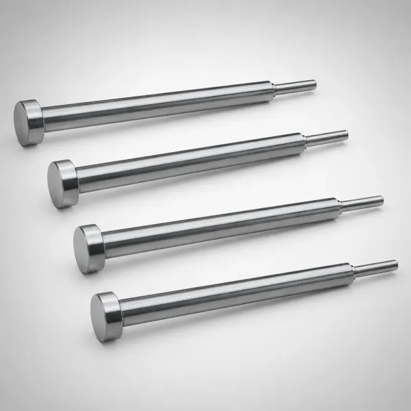
Never ream a worn button to a larger ID. Reaming grows the opening by 0.05-0.1 mm, which adds 0.025-0.05 mm of clearance per side. That single operation can push a 1.0 mm steel die past its burr limit in one shift.
Replacement Triggers
Replace the button when the ID has grown 0.02-0.05 mm past baseline, or when the edge is chipped. Replace it when roundness exceeds 0.005 mm, or when galling marks appear on the wall. Each trigger is measurable, so the call is not a judgment.
Standard die buttons cost $30-$150, a typical industry range. DieStrike supplies standard punches, ball-lock punches, and die accessories with 3-7 day delivery, so a scheduled button swap fits a normal maintenance window.
For runs above 500,000 strokes, carbide buttons at HRA 88-92 deliver 3-5 times the die life of tool steel, typical figures. The higher insert cost pays back on wear items and line time.
Check button retention on every teardown. A loose button shifts under cutting load, changes clearance dynamically, and shows up as one-sided burr with a healthy-looking punch.
Stripper, Pilots, and Alignment
Clearance is a three-dimensional geometry. The punch, the die opening, and the stripper bore must share one axis. If any of them drifts, the effective clearance on one side of the cut changes even when the punch and button still measure correctly.
Stripper bore wear is the quiet killer. The stripper guides the punch on the downstroke, and a bore worn 0.02-0.05 mm lets the punch run off-axis. The result is one-sided burr and one-sided edge wear on both punch and button.
Pilot wear shifts the strip between stations. A pilot OD worn 0.01-0.02 mm lets the strip move, so the cut lands off the previous station's geometry. Edge condition then varies station by station on the same strip.
Guide post and bushing clearance on the die set runs 0.01-0.02 mm on precision dies. Clearance above 0.05 mm means the die set no longer aligns the plates, and no amount of punch maintenance fixes that.
Run a push-through test after every service. A calibrated pin or a slug from the die passes through the stripper bore, the punch position, and the die opening without hang-up. Hang-up identifies the misaligned component before it costs a shift.
Check stripper spring pressure in the same window. The stripper must hold the strip flat against the die before the punch lands. Pad parallelism should hold to 0.01 mm. A misalignment of 0.03 mm produces measurable one-sided burr, and a worn spring produces it intermittently.
The Maintenance Schedule
The schedule below matches checks to wear rates. Run the interval that comes first, strokes or calendar time. Every row has a tool, a trigger, and a cost of skipping, so the schedule runs without opinions.
| Interval | Check | Tooling | Trigger | Cost of Skipping |
|---|---|---|---|---|
| Per shift | Burr visual, slug condition, lube check | Loupe, sample part | Visible burr or pulled slug | Scrap batch, die damage |
| Weekly or 50k strokes | Burr height, edge radius, stripper bore | Dial indicator, loupe | Burr over 5-10% of stock, edge over 0.05 mm | Unplanned regrind, line stop |
| Monthly or 200k strokes | Punch OD, die ID, clearance calc, pilots | Micrometer, pin gauge | Drift over 0.02 mm per side vs baseline | Burr rejects, faster wear |
| Quarterly or 500k strokes | Alignment, springs, button retention | Push-through pin, spring tester | Misalignment over 0.03 mm | One-sided wear, slug jams |
| Annual or 1M-2M strokes | Full teardown, CMM audit, wear parts | Bench, CMM | Any component past wear limit | Rebuild at $5,000+, typical |
← swipe to scroll →
Table: typical industry figures; verify against your program.
Log every check in the die book, even the pass rows. A trend line of clearance per station predicts the next regrind date within a few thousand strokes. That prediction is what turns maintenance from a cost into a schedule.
DieStrike applies this schedule on progressive dies built under IATF 16949, with stamping die lead times of 2-5 weeks. The mold repair and maintenance service covers the rework side when a die comes back with damage beyond wear.
Failure Modes and Fixes
Most progressive die problems are clearance problems wearing a costume. Match the symptom to the measurement before you touch a tool. The table below pairs the six common failures with the check that confirms them.
| Symptom | Likely Cause | Confirm With | Fix |
|---|---|---|---|
| Heavy burr on die side | Clearance too small or dull edges | Measure clearance, check edge radius | Regrind, correct clearance |
| Heavy burr on punch side | Clearance too large | Die ID vs baseline record | Replace button or punch |
| Slug pulls with punch | Clearance drift, dull edge, no slug control | Slug condition, edge radius | Regrind, add slug ejector or vacuum |
| One-sided burr | Misalignment in stripper, pilot, or die set | Push-through test | Align, replace worn guides |
| Galling on punch side | Poor lubrication, tight clearance, coating loss | Surface inspection | Fix lube, correct clearance, re-coat |
| Chipped edges | Jammed slug, hard inclusion, misalignment | Edge inspection, slug check | Remove cause, replace part |
← swipe to scroll →
Table: typical industry figures; verify against your program.
One measurement discipline covers all six rows. When a symptom appears, measure the clearance first, then the edge, then the alignment. Fix the cause, not the part.
The Die Book
A maintenance program without records is a rumor. The die book turns every check into a trend line, and trend lines predict failures before they cost a shift.
Start the book at tryout. Record punch OD, die opening ID, per-side clearance, edge photos, and a sample part for every station. That baseline is the reference every later reading compares against.
Log every regrind with the date, the stroke count, the stock removed, and the burr height before and after. Log every button replacement with the reason. After three or four service events, the book shows the wear rate per station, and the next regrind date is a forecast, not a guess.
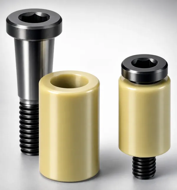
Keep the spare parts list in the same book: punches, die buttons, pilots, stripper springs, and slug control components for each station. DieStrike stocks standard punches, ball-lock punches, ejector pins, and mold accessories with 3-7 day delivery, so the annual parts order consolidates into one purchase.
DieStrike builds and maintains tooling for TE Connectivity, Amphenol, Luxshare, and Dongshan Precision under IATF 16949 across 120+ machines. Those programs run the same record standard. DFM feedback lands within 24 hours, and selection advice with a cost breakdown lands within 48 hours.
FAQ: Punch Clearance
Q1. What is the correct punch clearance for 1.0 mm steel?
Mild steel runs 6-8% per side, so 0.06-0.08 mm. The die opening is punch OD plus 0.12-0.16 mm total. Confirm on tryout and lock the value into the die book.
Q2. How do I know when to regrind a punch?
Regrind when burr exceeds 5-10% of stock thickness or when the edge radius passes 0.05-0.1 mm. Typical intervals run 100,000-200,000 strokes on mild steel and 50,000-100,000 on stainless.
Q3. Does regrinding change the clearance?
No. Face regrinding restores edge sharpness only. Per-side clearance changes when the punch OD or the die opening ID changes, so re-measure both in the same service window.
Q4. Why does the slug stick to the punch?
Clearance drift, dull edges, missing slug control, or a heavy lubricant film. Regrind, add a slug ejector or vacuum, and check the lubricant film thickness.
Q5. How much does punch clearance maintenance cost?
Regrinding a punch set runs $100-$300, and a standard die button runs $30-$150, typical industry figures. An unplanned stop runs $150-$300 per hour plus scrap and tooling.
The Bottom Line
Punch clearance is a measured value, not a set-and-forget number. Burr tells you when, the die book tells you how fast, and the schedule keeps both honest. Skip the checks and the line pays the bill. Run them and the die keeps cutting.
Send us your part drawing for DFM feedback within 24 hours, or get punch selection advice and a cost breakdown within 48 hours.
KEEP READING
Related Reading
5 Mold Cooling Channel Design Tips for Faster Cycles
Mold maker's 5 cooling channel design rules: channel-to-cavity distance 2-2.
Read articleArticle5 Shrinkage Compensation Rules for Mold Design
Shrinkage compensation decides mold accuracy. Five rules: material rates from 0.3% to 2.
Read articleArticle5 Ways to Reduce Mold Cost Without Cutting Quality
Five proven ways to reduce injection mold cost without cutting quality: DFM before quoting, right-sized cavity count,…
Read articleArticle7 Gate Design Best Practices for Balanced Filling
Mold maker's 7 gate design rules for balanced multi-cavity filling: gate depth 50-80% of wall thickness, land 0.5-1.
Read articleNEXT STEP
Ready to Start Your Mold?
Send us your element dimensions or part numbers — our team responds within 24 hours with pricing and lead time.

Written by
Ray ChanMold Buyer's Guide Author · Precision Mold Manufacturing Specialist. Ray helps global importers, distributors and OEMs source factory-direct molds and mold parts.