
How to Design Blow Molding Molds: EBM, IBM and ISBM Tooling
Table of Contents
A blow mold that runs a 0.3 mm wall on one flank instead of the 0.6 mm on the print will pass the first shot and fail a drop test three weeks later. In extrusion blow molding the wall is set by the parison, the pinch-off and the cooling layout, not by a pressure dial on the machine. A 2 L HDPE jug tool that misses its wall map usually needs the neck insert re-cut, and that re-cut runs 5 to 10 working days plus a fresh trial before the line restarts. This guide sets out the tooling numbers behind extrusion blow molding, injection blow molding and injection stretch blow molding.
Every figure below is a typical industry value for the mold body, and each one needs checking against the resin datasheet and the blow molding machine before a drawing is released.
The Snapshot
- Blow ratio of 2 to 4 to 1 on EBM. A 25 mm parison blown into a 50 to 100 mm cavity doubles to quadruples the diameter, and any ratio above 4 to 1 thins the blow corner below 0.5 mm.
- Cooling is 60 to 70 percent of the cycle. A 2 L HDPE jug on a 12 second cycle spends 7 to 9 seconds cooling, so the cavity water layout sets the output, not the extruder.
- Pinch-off land at 0.3 to 0.6 x parison thickness. A 2 mm parison needs a 0.6 to 1.2 mm land with a 0.5 mm radius, because a knifed edge cracks the bottom seam.
- Tool cost of 12,000 to 60,000 USD and 4 to 8 weeks. A 2 to 5 L HDPE extrusion blow mold lands there, against 3 to 5 times that for an equivalent injection tool.
The Three Blow Molding Routes
Each route builds a different tool and buys a different wall tolerance. Extrusion blow molding (EBM) extrudes a tube of melt, called a parison, then clamps a two-piece mold around it and inflates the tube with blow air at 0.2 to 1.0 bar. Injection blow molding (IBM) injection-molds a solid preform on a core pin and blows that preform in the same tool. Injection stretch blow molding (ISBM) molds a two-stage preform first, then reheats and stretches it axially and radially before the blow.
EBM is the workhorse. A single-station shuttle or wheel tool runs 0.5 to 10 L HDPE bottles, jugs, ducts and fuel tanks at 500 to 5,000 parts per hour, with 2 to 12 cavities on one mold. Tool cost is the lowest of the three because the cavity half is a shell with no core, no runner and no manifold. The resin side, from melt index to shrinkage, sits in the HDPE material guide.

IBM holds a tighter neck and wall. The preform is injection-molded to a 0.8 to 2.5 mm wall, so the blown part holds a 0.1 to 0.3 mm wall spread against 0.3 to 0.6 mm on a typical EBM bottle. The price is a tool that carries an injection manifold, a core pin and a blow station, which lands at 2 to 5 times an EBM pair.
ISBM splits the tool in two. The preform mold is the real tool, and the blow mold is a two-piece shell that only shapes the final wall. Axial stretch runs 2 to 2.5 times and hoop stretch 2 to 3 times, which orients the PET and gives a 0.2 to 0.5 mm wall with a burst pressure above 10 bar.
| Route | Typical parts | Parison or preform | Blow pressure | Wall control | Tool cost index |
|---|---|---|---|---|---|
| EBM | 0.5 to 10 L HDPE and PP bottles, jugs, ducts | Extruded parison, 1 to 6 mm wall | 0.2 to 1.0 bar | 0.3 to 0.6 mm spread | 1x |
| IBM | 10 mL to 1 L bottles with a tight neck thread | Injection preform, 0.8 to 2.5 mm wall | 2 to 10 bar | 0.1 to 0.3 mm spread | 2 to 5x |
| ISBM | 0.2 to 2 L PET bottles and jars | Two-stage preform, 2 to 4 mm wall | 20 to 40 bar | 0.2 to 0.5 mm, oriented | 2 to 4x, preform tool leads |
← swipe to scroll →
Table note: pressures, wall bands and cost indexes are typical industry values by route. Confirm the blow pressure and the wall map against the machine datasheet and the resin supplier data before a tool is released.
Tool Construction and Materials
An extrusion blow mold is a shell, not a block. The two halves for a 2 L jug weigh 10 to 40 kg each, which is light enough for a shuttle to swing and light enough for a manual change in 10 to 20 minutes. That low mass is why aluminium, not hardened mold steel, carries most of the cavity surface.
Aluminium cavity halves run 25 to 40 HRC on the anodized working face, and they move heat out of the wall 3 to 5 times faster than a 1.2343 steel shell. The trade is wear. A hard-anodized face holds a 0.02 to 0.05 mm surface build and survives 500,000 to 2,000,000 shots on an unfilled HDPE part.
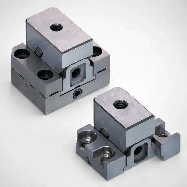
Beryllium-copper goes where heat and wear both matter. A BeCu insert at 50 to 52 HRC sits in the neck and in the pinch-off block, because those are the two zones that set the part and take the flash load. It draws heat 3 to 5 times faster than steel, which cools a thick neck ring 2 to 4 seconds sooner than an aluminium land of the same size.
The neck and handle inserts sit in the parting line on purpose. A separate pocket, located to a 0.05 mm fit and bolted on a 40 to 60 mm circle, lets the tool be re-cut 3 to 5 times across its life without touching the shell. The neck thread and the handle bridge are cut into the insert, never into the main cavity block.
Parison Control and Blow Ratio
Wall thickness is a parison problem before it is a mold problem. The die head extrudes the parison through a 5 to 15 mm pin gap, and the tube wall lands at 1 to 6 mm depending on that gap and on the die swell of the melt. Die swell adds 10 to 30 percent to the gap for HDPE, so the pin gap is not the finished wall.
Blow ratio equals the maximum part cavity diameter divided by the parison diameter. A part blown at 3 to 1 from a 2 mm parison wall finishes at roughly 0.6 to 0.7 mm on the widest section, because the wall thins in proportion to the stretch.
A 1 mm thickness drift on the parison prints a 0.3 to 0.5 mm wall drift on a 100 mm part. That single number explains most wall rejects in blow molding. The parison programmer, a 10 to 30 point profile over a 200 to 500 mm drop, exists to fight that drift by thickening the parison where the blow stretches it most.
Keep the blow ratio in a 2 to 4 to 1 window. Above 4 to 1 the blow corner starves, because the melt reaches the corner last and thinnest. Below 2 to 1 the parison is too fat for the cavity, so the closing halves pinch the melt into a fold and a cold fold line shows on the surface.
Neck, Pinch-Off and Seam Design
The pinch-off is the hardest working edge in the tool. It closes on the parison, compresses the wall and welds the seam that becomes the bottom of the bottle. The land width runs 0.3 to 0.6 times the parison thickness, so a 2 mm parison takes a 0.6 to 1.2 mm land.
Radius the land, never knife it. A 0.5 mm radius minimum on the pinch-off edge gives the weld a stress-friendly root. A sharp edge cuts the parison instead of welding it and leaves a 0.2 to 0.4 mm crack starter at the seam. A land that is too wide fails to squeeze the two walls together, so the seam stays open and leaks at 0.5 bar of test pressure.

The neck runs on a calibration sleeve. The blow pin enters the parison at the neck end, and a sleeve or a wedge sets the neck inner diameter to plus or minus 0.1 mm while the material is still hot. A 0.05 to 0.1 mm clearance between the pin and the sleeve lets the neck draw down without trapping a flash ring. Neck ovality above 0.1 mm kills an automatic capper, so the calibration land is ground, not milled.
Handles and the through-handle void are formed by the two halves closing on the parison. Keep the web around a handle bridge at 1.5 mm minimum, and vent the handle pocket so trapped air leaves before the melt reaches it. A handle that blows thin or splits at the bridge is usually a venting or blow-ratio problem, not a wall problem.
Cooling and Cycle Time
Cooling is 60 to 70 percent of the cycle in extrusion blow molding, and the mold is where that time is spent. Chilled water at 10 to 20 °C runs through the cavity half, and the parison touches that metal at 180 to 220 °C. Heat leaves the wall through the shell and the water circuit, so the circuit layout sets the output.
Gun-drill the cavity half with 10 to 12 mm channels on a 15 to 25 mm pitch, and keep the flow turbulent at 4 to 8 L/min per circuit. A laminar stream in a 12 mm channel carries about half the heat per degree that a turbulent one does. Split the half into 2 to 4 parallel circuits at the base, the body and the shoulder instead of one long series loop.

The wall thickness of the tool drives the cycle as much as the water does. A 0.5 mm of extra steel behind the cavity adds 8 to 15 percent of cycle time, because the heat path from the plastic to the water grows. Keep the cavity wall at 2 to 4 mm directly under the part surface, then thicken behind it for structure.
Cooling time scales with the square of the plastic wall. A 0.4 mm wall cools in about 2 to 4 seconds and an 0.8 mm wall in about 8 to 12 seconds at the same water temperature. That is why a wall map, not a single nominal wall, belongs on the drawing and drives the cutter path in the cycle time reduction guide.
Uneven cooling shows up in the base first. A 5 to 10 °C imbalance across the base insert produces 0.3 to 0.8 mm of base runout on a 100 mm bottle, and a bottle that is not flat on the base rocks on a conveyor and jams a filler. Balance the base circuit before chasing any other defect, and check it with a surface probe at four points after warm-up.
Venting and Blow-Pin Design
Air trapped between the parison and the cavity has to leave, or it becomes a blow spot. The parison seals the cavity as it inflates, so any pocket that is closed off early holds its air against the melt. That air stops the wall from contacting the metal, the wall stays thin there, and the surface shows a glossy dent after the part cools.
Vent the blow-pin seat and the cavity edges at 0.02 to 0.05 mm. A deeper slot leaves a witness line as the melt extrudes into it, and a shallower one plugs with a dust film after 20,000 to 50,000 shots. Run parting-line vents every 20 to 30 mm along the periphery, and always vent the two ends of the pinch-off, because those are the last places the air can reach.
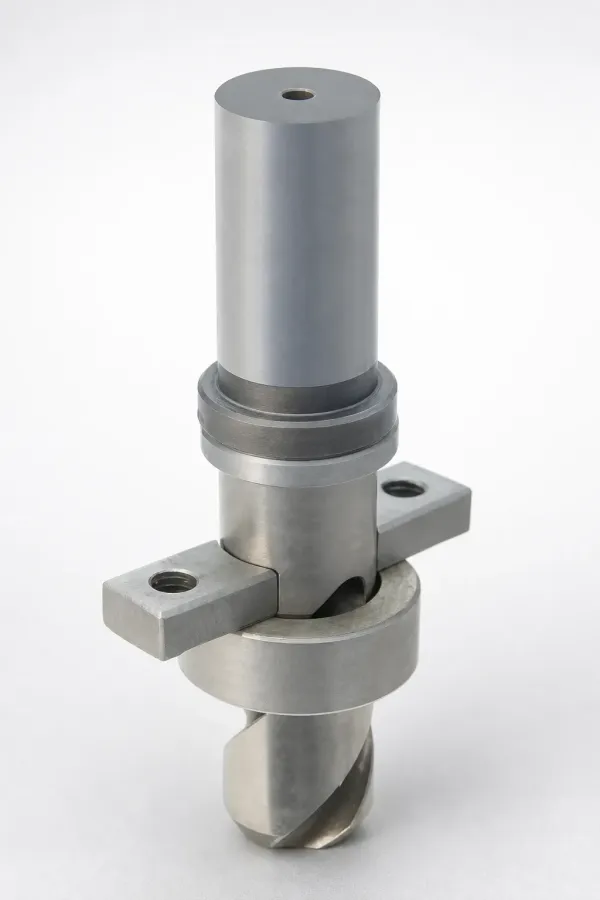
The blow pin does three jobs at once. It injects the blow air, it sets the neck inner diameter, and it cools the neck from the inside. Size the air hole at 1 to 3 mm, keep the pin-to-sleeve clearance at 0.05 to 0.1 mm, and run a separate water circuit through the pin so the neck does not stay soft while the body sets. On a handle or a recessed grip, add a mechanical vent or a small vacuum pull, because blow air at 0.2 to 1.0 bar will not push gas out of a closed pocket on its own.
Ejection, Trimming and Calibration
The blown part leaves the tool on the flash tail, and the tail is what the take-out grips. Eject with a stripper or a set of knock-out pins that push on the flash and the base, never on a thin wall. A point load on a 0.3 mm wall at 80 to 120 °C leaves a dimple that a drop test finds.
Trim in a die, not by hand. A trim die cuts the flash to a 0.5 to 1.0 mm land on a 5 to 10 t press, and it holds the neck and the base in the same fixture so the cut stays square to the part. Hand trimming a 2 L jug to a 0.5 mm land is a 15 to 30 second job per part, which on a 900 part per hour line is not a job at all.
Calibrate the neck and hold the top seam. A calibration sleeve sets the neck inner diameter to plus or minus 0.1 mm, and a take-out gauge holds the part against the neck while the body cools for 2 to 4 seconds. Without that hold, the top seam relaxes, the neck tips 0.3 to 0.6 mm off axis and the capping head misses.
Prove the tool with a first-shot wall scan. Cut one part at 12 points along the wall map, section it and measure it against the print. Look for a wall inside plus or minus 10 percent of nominal and a base runout under 0.5 mm. A tool that passes the wall scan and holds the neck at plus or minus 0.1 mm is ready for a capability run.
PCR and Recycled HDPE Tooling
Post-consumer recycled HDPE changes the tool, not just the resin. PCR content runs 25 to 100 percent in a growing share of bottles and jugs, and every point of PCR brings ash, gels and colour variation into the parison. A tool built for virgin HDPE will run PCR, but it will not run it well without changes.
Ash and gels are the first problem. A gel passes the die gap as a hard lump and prints a 0.2 to 0.5 mm bump on the wall, and ash from paper labels and closures abrades the die. Above 60 percent PCR, put a melt filter at 60 to 120 µm in front of the die head, and widen the pinch-off land by 0.2 to 0.4 mm so the seam welds through the contamination instead of cracking at it. This is the same gel and regrind reasoning that sets vent and gate layout in the recycled plastics mold guide.
PCR also runs a wider melt window and a slower cycle. The melt index spread across a batch moves the parison wall, so a tool that fights a 1 mm parison drift needs a tighter programmer profile, not a fatter parison. Expect 5 to 15 percent more cycle time on a high-PCR run.
Contamination wears the tool. Ash in PCR acts as a mild abrasive on the die, the blow-pin seat and the pinch-off edge, so a hard-anodized or chrome face lasts longer and the pinch-off block belongs in a replaceable insert. Review the parison and the die condition every 100,000 to 200,000 shots on a PCR line.
Common Blow Mold Failures
Blow mold defects repeat, and each one carries a number that points at the cause. A thin corner, a split seam, a warped base and a blow spot cover most of the scrap a blow molding line produces, and all four trace back to a tool geometry decision.
| Failure | Root cause in the tool | Number to check |
|---|---|---|
| Thin wall at the blow corner | Blow ratio above 4 to 1, or a cold parison reaching the corner last | Cavity diameter divided by parison diameter, keep 2 to 4 to 1 |
| Cracked bottom seam | Pinch-off land knifed instead of radiused | Land width 0.3 to 0.6 x parison, edge radius 0.5 mm minimum |
| Open or leaking seam | Pinch-off land too wide to compress the two walls together | Land under 1.2 mm on a 2 mm parison, clamp at 0.2 to 1.0 bar |
| Base runout and rocking | Uneven cooling across the base insert | Base temperature spread under 5 °C, runout under 0.5 mm |
| Blow spot or dimple | Plugged or missing vent at a closed pocket | Vent depth 0.02 to 0.05 mm, cleaned every 20,000 to 50,000 shots |
| Neck ovality and cap miss | Calibration land milled, or no take-out hold on the top seam | Neck inner diameter plus or minus 0.1 mm, hold 2 to 4 seconds |
← swipe to scroll →
Table note: failure causes and thresholds are typical values for HDPE and PP extrusion blow molding. Confirm the parison thickness, the wall map and the water setpoints from the trial record before changing tool geometry.
Two of those rows are opposite mistakes at the same edge. A cracked bottom seam and an open seam are the results of a knifed land and a too-wide land. Measure the parison thickness at the pinch-off before touching the land, because the land width is a ratio of a number that drifts with the die gap and the die swell.
The other pattern is cooling. A warped base, a neck that will not hold calibration and a wall that drifts across the cavity are three symptoms of one water imbalance. Fix the circuit balance and the surface probe spread before the tool reaches a 12 point wall scan.
Blow Mold Design Checklist
Run this list against the tool drawing before a blow mold is released to the shop. Each line carries the number that a reviewer should read off the drawing, not off the machine.
- Route and wall map. State the route, the part volume, the material and the wall map with the nominal and minimum wall, so the blow ratio computes in one line.
- Blow ratio 2 to 4 to 1. Show the parison diameter and the maximum cavity diameter, and confirm the ratio on the drawing.
- Pinch-off land 0.3 to 0.6 x parison. Land 0.6 to 1.2 mm on a 2 mm parison, a 0.5 mm radius minimum, and a replaceable pinch-off insert.
- Neck and handle inserts. Held on a 40 to 60 mm bolt circle with a 0.05 mm locating fit, sized so the tool can be re-cut 3 to 5 times.
- Calibration sleeve plus or minus 0.1 mm. Neck inner diameter ground to plus or minus 0.1 mm, pin clearance 0.05 to 0.1 mm.
- Cooling at 10 to 20 °C water. 10 to 12 mm channels on a 15 to 25 mm pitch, 4 to 8 L/min turbulent flow, base spread under 5 °C.
- Vent map. 0.02 to 0.05 mm vents at the blow-pin seat, the pinch-off ends and every closed pocket, with a clean-out interval written down.
- Acceptance evidence. A first-shot wall scan at 12 points within plus or minus 10 percent, a base runout under 0.5 mm, and a seal test that holds the rated pressure.
The checklist is also the tool file. A blow mold that carries its parison profile, its wall map, its water setpoints and its vent map in one package runs the same after a shutdown as it did on the trial day.
The Bottom Line
Blow molding mold design runs on a short list of numbers. Hold the blow ratio at 2 to 4 to 1, the pinch-off land at 0.3 to 0.6 times the parison with a 0.5 mm radius, the neck at plus or minus 0.1 mm, and the water at 10 to 20 °C with a base spread under 5 °C. Those four set the wall, the seam and the output of the tool.
The route decides the rest. EBM buys low tool cost and a 0.3 to 0.6 mm wall spread, IBM buys a 0.1 to 0.3 mm spread at 2 to 5 times the tool cost, and ISBM splits the investment into a preform tool and a blow shell. DieStrike builds precision blow molding molds and injection molds to IATF 16949, with plus or minus 0.005 mm mold accuracy, plus or minus 0.002 mm on EDM and jig grinding, HRC 62 cavity heat treatment, 120+ machines and DFM feedback in 24 hours.
Standard components ship in 3 to 7 days and tool lead times run 2 to 5 weeks, with tier-1 references that include TE, Amphenol, Luxshare and Dongshan. Route the part print, the wall map, the material, the volume and the neck spec through mold design and DFM, and the tool starts from a wall map rather than a guess.
KEEP READING
Related Reading
High-Density Polyethylene (HDPE) Material Guide
Density, melt index and shrinkage data for the resin that carries most extrusion blow molded bottles and jugs.
Read articleArticleHow to Design Molds for Recycled Plastics
How gel, ash and regrind content change gate, vent and cooling decisions inside a production tool.
Read articleArticleHow to Reduce Injection Cycle Time
The cooling, packing and ejection levers that trim a cycle without moving the process window.
Read articleServiceMold Design and DFM
IATF 16949 tool design reviews with wall mapping, blow ratio checks and 2 to 5 week lead times.
Read articleNEXT STEP
Ready to Start Your Mold?
Send us your element dimensions or part numbers — our team responds within 24 hours with pricing and lead time.

Written by
Ray ChanMold Buyer's Guide Author · Precision Mold Manufacturing Specialist. Ray helps global importers, distributors and OEMs source factory-direct molds and mold parts.