
HDPE Injection Molding: Material Guide for Closures and Buckets
Table of Contents
A 48 cavity closure tool shipped with a 2.5 percent shrink allowance taken from the datasheet average. The caps landed 0.6 mm under on diameter and out of round across the cavity set, and the thread gauges failed at T1. The fix was a re-cut ring set and two lost weeks of schedule. High density polyethylene shrinks 1.5 to 4.0 percent, and it shrinks unevenly, so the steel and the fill history decide what the part measures. This guide reads HDPE from the mold side: grade bands, shrink compensation, crystallization, gating, venting, regrind limits and the high-cavity patterns behind closure and container volume.
All figures are typical published values for molded HDPE grades, checked against supplier sheets and trial parts before any cavity is scaled.
The Snapshot
- Shrink of 1.5 to 4.0 percent, and anisotropic. Machine direction beats transverse by 20 to 50 percent, so gate position and pack history become part dimensions.
- Melt index from 0.3 to 80. Thin-wall grades at MI 20 to 80 fill 1 mm walls at flow-front speeds near 300 mm/s; MI 0.3 blow grades cannot keep up.
- ESCR by ASTM D1693 full-notch creep. Detergent closures need 100+ hours of survival time, and that rating, not tensile strength, picks the grade.
- Release in 15 to 30 seconds at a 20 °C mold. A 2 mm HDPE wall crystallizes fast enough to run 8 to 15 second closure cycles once the water lines keep up.
Why HDPE Runs a Different Mold Playbook
HDPE is the highest-tonnage injection polyolefin after polypropylene, and the PP material guide covers that side of the family well. The two materials share a low density, a waxy feel and near-zero water absorption, but they punish the toolmaker differently. Four differences move every design decision.
First, shrink. HDPE pulls 1.5 to 4.0 percent from melt to part, roughly double many commodity resins, and the direction matters as much as the amount. A cavity scaled on a single number produces round parts with the wrong diameter and flat parts that are not flat.
Second, melt viscosity. HDPE is thin and fast at processing temperature, especially at MI above 10. It fills long paths at low injection pressure, wets into every gap, and flashes through vents that would hold PP back.
Third, stress cracking. HDPE carries solvents and detergents well until a molded-in stress meets a surfactant. Environmental stress cracking then opens a path from a gate witness or an ejector-pin mark, and the part fails days after molding. Grade selection and gate design are the defense, not drying or cycle tuning.
Fourth, economics. A closure at 2 g sells resin by the tonne, so the program lives or dies on 8 to 15 second cycles across 24 to 96 cavities. The mold has to cool that fast, eject that fast and stay shut without flashing, and every rule in this guide serves that arithmetic.
HDPE Properties That Decide Tool Design
Published property ranges for molded HDPE read: density 0.941 to 0.965 g/cm³, melting point 128 to 135 °C, melt processing 180 to 260 °C, mold temperature 10 to 40 °C, tensile modulus 0.8 to 1.5 GPa, and elongation at break 100 to 600 percent. Three of those numbers drive steel decisions.
The density band sets stiffness and shrink at the same time. A 0.965 g/cm³ grade stands up in a 5 L pail wall and shrinks toward the low end of the range. A 0.941 g/cm³ grade flexes and shrinks toward the high end. Choosing density is choosing a cavity scale.
Thermal conductivity sits near 0.5 W/m·K, roughly double that of PP. Heat leaves a PE part faster than a PP part of the same wall, which is why 2 mm sections release from the core in 15 to 30 seconds at a cold mold. Cooling design should exploit that, not fight it. Water absorption under 0.01 percent also means an HDPE part does not grow with humidity the way nylon does, so a shrink trial measured on the first shipment still predicts next quarter's parts.
Service temperature is the ceiling to respect: HDPE softens toward 80 °C and creeps under sustained load above roughly 60 °C. Check the plastic material selection guide before specifying PE for anything above 60 °C continuous.
Grade Selection: Melt Index, Density and ESCR
Injection HDPE grades sort by melt index first and density second. MI is measured at 190 °C under 2.16 kg and describes how the melt moves, not how strong the part is. The working bands for molding look like this.
| Application band | Melt index | Density | Mold-side consequence |
|---|---|---|---|
| Thin-wall tubs, deli containers | 20 to 80 g/10 min | 0.950 to 0.960 | Fills 1 mm walls near 300 mm/s; vents and clamp must keep up |
| Closures, caps, pail handles | 5 to 20 g/10 min | 0.955 to 0.965 | Balanced fill and toughness; the workhorse band for 24 to 96 cavities |
| Buckets, crates, pails | 1 to 8 g/10 min | 0.941 to 0.955 | High ESCR and impact; slower fill, longer pack on thick ribs |
| Blow and extrusion grades | 0.3 to 1 g/10 min | 0.941 to 0.960 | Fail on injection fill speed; do not substitute for a molded part |
← swipe to scroll →
Table note: bands are typical published ranges for commercial injection grades. Confirm the actual grade sheet, since supplier families overlap these MI values.
The failure mode worth naming: a plant buys a cheap blow-molding grade because the resin truck cannot tell the difference. At MI 0.7 the melt will not cross a 300 mm flow path in a 1 mm wall before the skin freezes, and the short shot arrives at 85 percent fill.
For chemical contact parts, the deciding number is ESCR, not tensile strength. ASTM D1693 full-notch creep testing holds a notched specimen under stress in a wetting agent, and detergent closures typically need 100+ hours to failure. A grade rated at 40 hours passes every mechanical test in the lab and fails in the field when surfactant meets molded-in stress.
Request the D1693 hours on the purchase order for anything carrying cleaning products, motor oil or personal-care formulas, and pair the ESCR grade with the gate rules below.
The Shrinkage Reality: 1.5 to 4.0 Percent
HDPE shrinkage splits two ways: it is large, and it is not equal in every direction. Machine direction shrink beats transverse shrink by 20 to 50 percent on the same part, because flow orients the chains and crystallization locks that orientation in. A 200 mm lid scaled at 2.8 percent needs 6 mm of cavity steel, and its roundness then depends on where the gate sat.
Gate distance becomes a dimension. Material near the gate sees high pack pressure, orients heavily and shrinks more along flow. Far from the gate the melt slows, orientation relaxes, and the shrink band shifts. Two cavities with identical steel but different runner balances produce lids that differ by 0.3 to 0.5 mm on diameter.
Because of this, the datasheet single-point shrink number is a starting guess, not a manufacturing value. The sequence that works: run a shrink trial part, measure it on the CMM at 24 hours after molding, cut production steel to the measured machine-direction value, and hold transverse features at the measured cross value. Mold-flow shrink bands set the first-cut steel within 0.2 to 0.3 percent; the trial closes the rest.

Process moves shift shrink too, and each one is a trap if the drawing assumes a fixed value. Higher melt temperature raises shrink by roughly 0.1 to 0.2 percent. Longer pack pushes shrink down because the cavity forces more mass into the same steel. A colder 10 °C mold chills the skin early and lowers the total draw.
The disciplined fix is a shrink statement per program: grade, MI, setpoints, pack profile, and the measured machine and transverse numbers. Any process change reopens the statement, because on HDPE the process is part of the tolerance stack.
Crystallization, Cooling and Cycle Time
HDPE is 60 to 80 percent crystalline at room temperature and crystallizes fast as it cools. Most of the shrink above happens during that crystallization, in the first seconds after the gate seals. This is good news for cycle time: a 2 mm wall releases from the core in 15 to 30 seconds at a 20 °C mold, and thin closure sections run 8 to 15 second cycles.
Cooling capacity, not pack profile, owns the cycle on PE parts. The melt enters at 200 to 260 °C and releases heat quickly, so the water lines have to carry it away continuously. Run circuits at 4 to 8 L/min in turbulent flow; a laminar stream carries roughly half the heat per degree. Where straight drilling cannot follow a bucket core, baffles, bubblers or conformal lines keep the surface within a few degrees of setpoint.
Mold temperature sits at 10 to 40 °C on HDPE tools. The low end speeds the cycle and lowers shrink; the high end buys surface copy and weld strength at the gate. Whatever the setpoint, symmetry matters more than the number: core and cavity chilled unevenly by 5 °C or more will bow a flat lid toward the warm side.

Faster crystallization also sharpens the ejection window. PE grips hard: crystallization pull-down reaches 0.1 to 0.3 mm on a 100 mm core, so the part must leave before the grip tightens. Eject too early and a pail bottom stretches; too late and the part sticks. The underlying math is the standard cooling time calculation: wall thickness squared over thermal diffusivity, corrected for the water-side film coefficient.
One habit keeps this measurable: log cavity-face temperature at six points each shift. A tool that drifts from 20 °C to 28 °C on the far cavities shows 0.2 mm of diameter spread before any press alarm fires.
Gate Design Rules for HDPE Parts
Low viscosity and a stress-cracking tendency make the gate the highest-risk 5 mm of steel on an HDPE tool. The melt arrives fast, the skin tears easily at the witness, and molded-in stress at the gate is where ESCR failures start.
On visible faces, use an edge or tab gate with a section of 0.4 to 0.8 mm thickness and 5 to 15 mm width. The wide, thin land lets the melt advance rather than jet, keeps the witness below the cosmetic surface after break-off, and preserves weld strength because the front enters the cavity as a sheet.
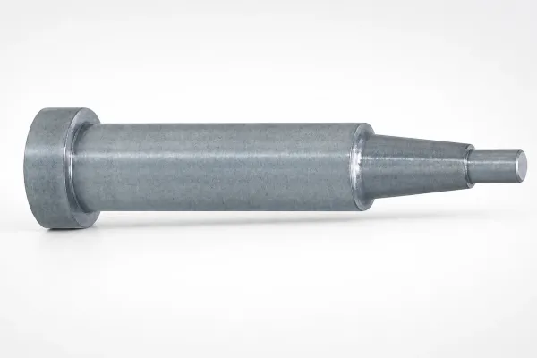
Submarine and tunnel gates work on caps and small housings when the part separates from the runner automatically. Keep the cutter at 1.5 to 2 times the land section so the gate shears cleanly. On a 2 g closure the sub gate vestige should stay under 0.5 mm after twist-off.
Never use a pinpoint gate on HDPE. The small land shears the melt, rips the oriented skin as the part cools and pulls, and plants a stress riser at the one point a detergent will find. On MI 20 to 80 thin-wall grades, a pinpoint also jetts across a fast-filling cavity and leaves a snake of frozen material on the surface. The gate type selection guide carries the section math behind these limits.
Runner sizing follows the same logic. Full-round runners at 4 to 8 mm with radiused corners keep pressure loss low on long multi-cavity paths. Valve gate nozzles at 0.3 to 0.6 mm land diameter delete the runner on 24+ cavity closure stacks, sealing on a steel land rather than frozen plastic. Hold nozzle temperature within ±1 °C; HDPE skins onto a cold nozzle in seconds and freezes a gate shut.
Freeze the gate plan into the DFM before cutting steel and re-check it against the fill map at T1. Once runner balance shifts the last-fill point, a gate that looks correct on the drawing can still land a weld line over a screw boss, and moving it after heat treat costs 3 to 5 days of wire-EDM rework.
Venting, Surface Finish and Ejection
HDPE wets steel. The melt is thin enough to crawl into land depths that hold PP back, so vent depth on PE tools runs 2 to 4 micrometres with a 2 to 4 mm land before the relief. Deeper than 4 µm turns the vent into a flash channel with a permanent fin; shallower traps air and burns the last-fill corner at 230 °C. Clean vents every 5,000 to 10,000 shots, because PE leaves a thin wax film that closes a 3 µm channel quietly.
Cores and cavities get polished, and for HDPE the reason is grip rather than gloss. PE sticks to a match-marked surface and cavitates on ejection; an Ra 0.2 to 0.4 µm polish on deep cores reduces the drag that stretches a bucket skirt. Texture is the exception: a textured pail releases better because the land breaks the vacuum, but texture eats draft.
Draft should start at 1.5 degrees and reach 2 degrees on textured or deep walls such as buckets and crates. PE grips with a friction coefficient near 0.3 to 0.5 against steel, and 1 degree of draft on a 150 mm deep wall leaves little release path to break that grip.
Ejection needs area, not force. Sleeve pins under rib bosses and pins of 6 mm or larger on pail bottoms distribute the push; a 3 mm pin on a hot HDPE skin leaves a visible dimple at 1 to 2 MPa. Air assist at 0.2 to 0.4 MPa through the core breaks the vacuum before the first pin stroke. High-cavity closure tools use the same stripper-plate architecture as thin-wall packaging stacks, covered in the ejector system design guide.
Part Behavior: Creep, Snap Fits and Hinges
HDPE is stiff but it is not rigid under time. Creep modulus for a 0.960 g/cm³ grade under sustained load falls toward half the short-term modulus over 1,000 hours, which changes how a pail handle, a crate corner post or a press-fit boss must be sized. Design long-life loads against the creep curve at 23 to 40 °C, not against the tensile modulus printed on the sheet.
Snap fits exploit the flip side of the same property: HDPE takes large strain and returns. A cantilever snap at 1.5 mm wall can deflect 15 to 25 mm at the tip within a 1 to 2 percent strain limit for a 100-cycle assembly, provided the root radius stays above 0.5 mm.
Living hinges need honesty about the family boundary. The 0.15 to 0.25 mm hinge lands that survive millions of flexes belong to homopolymer PP, not to HDPE. A PE hinge at the same thickness fatigues and crazes at a small fraction of that count. If the drawing calls for a flip-top with a certified hinge life, the material moves to PP and the shrink model changes with it.
Weld lines behave better than most buyers fear. HDPE's low viscosity lets fronts merge at relatively low pressure, and a 1 mm wall that welds at 90 degrees can keep 70 to 85 percent of base strength above 220 °C melt. The catch is placement: gate-driven orientation keeps the line invisible only when fronts meet warm and slow, so land meeting points on ribs or hidden faces.
Regrind Limits and Lot Control
PE is the most regrind-tolerant resin in the catalog. Clean, single-color runner and sprue at 10 to 25 percent runs without a visible property break on closures and containers, and many plants hold 20 percent as the standard. Nylon starts breaking spec near 10 percent from hydrolytic chain scission, which is why HDPE programs stay profitable on scrap-heavy first shifts.
Three limits still apply. The first is thermal history: each pass through the barrel clips chains, and MI rises roughly 5 to 15 percent per regrind cycle at 240 °C, shifting both fill and shrink. The second is color: natural-to-black transitions carry specks, so segregate regrind by color and reject cross-contaminated lots at 1 percent visual. The third is ESCR: notch creep hours fall with repeated shear, so chemical-contact parts use runner-only regrind at 10 percent maximum and log the lot number.
| Regrind condition | Allowed level | Watch item | Reject trigger |
|---|---|---|---|
| Runner only, same color | 20 to 25 percent | MI drift up 5 to 15 percent per pass | MI band shift beyond one grade step |
| Mixed sprue and parts | 10 to 15 percent | Contamination and fines | Visible specks at 1 percent |
| ESCR chemical-contact parts | 10 percent max | D1693 hours falling by lot | Any lot under 100 h FNCT |
| Cross-color or cross-grade | 0 percent | Lot traceability | Immediate quarantine |
← swipe to scroll →
Table note: percentages are typical industry practice for injection HDPE. Validate against the grade supplier's regrind statement before program release.
Put the regrind cap and the MI test frequency in the purchase order, with a lot certificate stating the measured MI as delivered. A program that silently runs 35 percent regrind fills faster, shrinks differently and cracks sooner, and the audit trail only finds it after the field returns start.
High-Cavity Tooling Patterns
The economic center of HDPE molding is the multi-cavity closure tool. A 2 g cap at an 8 to 15 second cycle across 48 cavities produces roughly 20,000 to 30,000 pieces per hour, and the tool architecture serves that arithmetic first. Cavity counts run 24 to 96 on caps, stack layouts double the count in one clamped opening, and family layouts group a pail with its lid when volumes match.
Balance decides whether 96 cavities mean 96 good parts. HDPE's low viscosity helps, because a runner at 30 to 60 MPa fill pressure equalizes drops that a nylon tool would leave starved. Still graduate runner cross-sections so every path lands within ±0.3 percent of the same part weight, verify with a 30-shot weight study at T1, and put the cavity map into the inspection report.
Valve gate hot runners at 0.3 to 0.6 mm land diameter dominate new closure tools because they delete the runner from the cycle and from the regrind budget. A 0.1 second timing spread across 48 pins shows up as flash on the late drops, so pin fit at ±0.01 mm matters as much as the nozzle layout. Cold-runner 3-plate tools stay valid below 24 cavities.
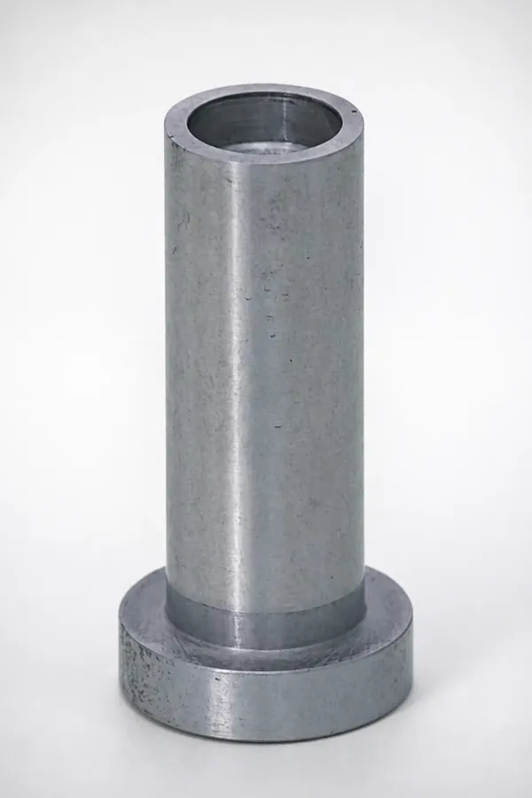
Steel inside these tools is conservative: hardened stainless cavities at HRC 50 to 54, or pre-hardened P20 family at HRC 32 to 36 for shorter programs, holding ±0.005 mm mold accuracy for 1 to 2 million shots. Ejector sleeves and guide pins are standard components shipped in 3 to 7 days, so a wear part never becomes a week of downtime.
HDPE vs PP: Comparison Table
PP and HDPE split almost every polyolefin program between them. The decision comes down to five numbers, because each one re-scales the cavity or re-draws the gate. The table compares typical injection grades at equal wall thickness.
| Property | HDPE | PP | Mold-side consequence |
|---|---|---|---|
| Shrinkage | 1.5 to 4.0 percent | 1.0 to 2.5 percent | HDPE cavities need more steel and a measured trial part |
| Stiffness at equal wall | 0.8 to 1.5 GPa | 1.1 to 1.6 GPa | HDPE needs 10 to 20 percent more wall or ribs for equal deflection |
| Temperature ceiling | 60 to 80 °C continuous | 90 to 110 °C continuous | Hot-fill and under-hood parts move to PP |
| Chemical behavior | ESCR is the watch item | UV oxidation is the watch item | Detergent contact picks HDPE; outdoor exposure picks stabilized PP |
| Resin cost | commodity band per kg | commodity band per kg | Part mass at equal stiffness often favors PP |
← swipe to scroll →
Table note: ranges are typical published values for general injection grades of both polymers. Confirm against the specific grade sheets before the shrink model is locked.
Read the rows as a decision order. Surfactant exposure picks HDPE and the ESCR band picks itself; hinge fatigue or hot filling moves the part to PP and the shrink model changes with the material.
The Bottom Line
HDPE molding is won in the steel before the first shot. A measured shrink model replaces the datasheet average, because 1.5 to 4.0 percent draw split 20 to 50 percent between directions is a tolerance stack, not a constant. The grade is chosen by melt index and ASTM D1693 hours, because fill behavior and stress cracking decide the field result. Cooling owns the cycle on a material that crystallizes in 15 to 30 seconds at a 20 °C mold, gates stay wide and thin because PE wets every land it meets, and regrind up to 25 percent is an economic advantage that only survives lot discipline.
DieStrike builds closure, container and industrial HDPE tooling to IATF 16949 with ±0.005 mm mold accuracy, hardened cavity steels to HRC 62, 120+ machines and tool lead times of 2 to 5 weeks, with standard components shipping in 3 to 7 days for tier-1 programs. If an HDPE program is on the calendar, send the part drawing and the chemical exposure list and the DFM response will name the shrink band, the gate plan and the grade before the steel is booked.
KEEP READING
Related Reading
How to Choose Mold Cavity Count: Volume, Tolerance and Cost
Cavity count math for 8 to 15 second commodity cycles and tight closure tolerances.
Read articleArticleHow to Design Molds for Thin-Wall Packaging
Fill speeds, venting and steel choices when 1 mm walls arrive at 300 mm/s.
Read articleArticleHow to Design Stack Molds: Layout, Gates and Heat
Stack tooling doubles cavities per platen on closure and container programs.
Read articleServiceInjection Mold Manufacturing
IATF 16949 mold building with ±0.005 mm accuracy and 2 to 5 week lead times.
Read articleNEXT STEP
Ready to Start Your Mold?
Send us your element dimensions or part numbers — our team responds within 24 hours with pricing and lead time.

Written by
Ray ChanMold Buyer's Guide Author · Precision Mold Manufacturing Specialist. Ray helps global importers, distributors and OEMs source factory-direct molds and mold parts.