
How to Design an Ejector System: Pin Layout, Force and Stroke
Table of Contents
Shot 14 of a POM gear housing mold ejected with pin 6 bent 0.3 mm. A white crescent sat across the rib that pin was supposed to push. Its 20 pins totaled only 0.8% of the projected area in tip area, far too little for a high-shrink resin. Cavity 2 stuck every third cycle, and the fix meant re-boring the ejector plate, not changing the barrel temperature. Ejection is a system, and it was sized wrong on the drawing board.
This guide is the sizing method that prevents that failure. It covers ejection force, total pin area, layout rules, diameter, and buckling. Clearance, draft, stroke, and return follow, each with a checkable number. Material-side process settings appear only where they feed a mold-side decision.
Values are typical industry practice and typical published material figures. Verify every one against your resin datasheet, your stress calculation, and your press data sheet before ordering components.
The Snapshot
- Estimate ejection force as F = p x A x friction, where p is demolding pressure at 3-15 MPa typical for low-shrink resins and 15-30+ MPa for high-shrink PA and POM.
- Size total pin-tip area near 1-3% of projected part area on average boss-and-rib parts. Thin walls and deep cores push the share higher.
- Standard ejector pins per DIN 1530 and JIS run 1.0-25 mm diameter. The smallest practical production pin is 1.0 mm, and 0.5 mm pins are specials.
- Keep unsupported pin length under L/D 20-25 to avoid buckling. A typical layout grid spaces pins 8-15 mm apart.
- Set ejection stroke at part depth plus 5-10 mm clearance. Confirm it against the press ejector stroke, typically 30-150 mm.
The Failure This Design Prevents
The classic ejector failure is not one broken pin. It is a system that was undersized at design and paid for it across the whole production run. Stuck parts, bent pins, and cracked ribs all trace back to three errors. Force is underestimated, pin area is too small, and pins sit where the part has no material to push on.
Each error is cheap to fix on a drawing and expensive after hardening. Re-boring an ejector plate on a hardened tool costs machining hours and a week of schedule on a 2-5 week program. Adding draft means re-cutting the core. Switching pin diameter means new bores and new catalog parts. Every one of those moves is a trial-floor emergency that should have been a DFM note.
The sequence that repeats across the industry is consistent. A tool opens with the part still gripping the core. The ejector plate advances, and the pins that do have support carry the load while the pins on unsupported flats bend or push through. The part leaves with local stress whitening or a dimple, and QC rejects it on the cosmetic face.
This design method exists so that conversation never starts. It sizes force first and converts it into pin area. It then checks diameter, length, stroke, and return against the press. When the numbers close, the tool ejects on shot one, and the trial spends its time on cosmetics and cycle, not on ejection rework.
Ejection Force: Where It Comes From
Ejection force comes from shrinkage grip. The resin shrinks as it cools and locks the part onto the core steel. Demolding breaks that grip and overcomes friction along every surface in contact.
Resin class sets the grip magnitude. Amorphous, low-shrink resins such as PC, ABS, and PMMA shrink roughly 0.4-0.7%. They release from polished steel at demolding pressures in the 3-15 MPa typical band. Unfilled PA6, PA66, and POM shrink about 1.5-2.5% typical. They lock onto the core as they crystallize, and the simple model puts their demolding pressure at 15-30+ MPa.
Molders estimate the total force with the formula F = p x A x friction coefficient. A is the projected area of the part hugging the core, in mm². p is the demolding pressure from the table below. The friction coefficient for polymer against polished mold steel at mold temperature typically runs 0.1-0.3.
Work one example. An ABS tray projects 4,800 mm², and with p at 5 MPa typical and a friction coefficient of 0.2, the estimate is 5 x 4,800 x 0.2 = 4,800 N. That is about half a tonne of stripping force. A POM part of the same footprint at 20 MPa and 0.2 gives 19,200 N, four times the force from the same geometry. High-shrink resin multiplies the ejection bill, and the pin layout must grow with it or fail.

The table below maps typical demolding pressure by material family. Treat it as a first-pass table, not a datasheet. Filled grades, mold temperature, cooling time, and draft all move the number. The molder verifies the estimate at T1 by reading ejector pressure on the press.
| Material Family | Typical Shrinkage | Typical Demolding Pressure | Ejection Behavior |
|---|---|---|---|
| PC, ABS, PMMA (amorphous) | 0.4-0.7% | 3-15 MPa | Light grip on polished cores. Gloss faces mark early |
| PP, PE (unfilled semicrystalline) | 1.5-2.5% | 8-15 MPa | Shrinks onto the core while cooling. Deep ribs grip hardest |
| PA6, PA66 (unfilled) | 1.5-2.5% | 15-25 MPa | High dry-as-molded grip. Moisture level changes release force |
| POM homopolymer and copolymer | 1.8-2.5% | 15-30+ MPa | Strongest grip of unfilled grades. Stress-check every pin tip |
← swipe to scroll →
Table note: Pressure bands are typical industry ranges for the simple F = p x A x friction model. Verify with the resin datasheet and a trial-floor ejector pressure reading before production.
Two refinements make the estimate honest. First, the projected area that grips is the footprint over the core, not the whole part outline. Open geometry, slots, and side actions reduce it. Second, friction falls as draft rises, so a part with 1° draft per side needs less force than the table suggests.
Pin Area and Count: The 1-3% Rule
Force is only useful when converted into steel. The pins transmit the stripping force into the part, and the part has to carry that force at the pin tip without yielding. Pin-tip area is the design variable, and count follows from it.
The check is a bearing stress calculation. Divide the estimated total force by the combined area of all pin tips. The quotient must stay below the warm resin's compressive limit, which for common engineering resins at ejection temperature typically runs 25-75 MPa. Exceed it and the pin tip dimples the wall, whitens the surface, or pushes through a thin rib.
Molders collapse this two-step check into a layout rule of thumb. Total pin-tip area lands near 1-3% of projected part area on average boss-and-rib parts. The percentage is the arithmetic outcome of typical pressures, friction, and bearing limits. It holds for ordinary geometry and fails for extremes.
Convert the ABS tray example. The 4,800 N estimate divided by a warm bearing limit near 45 MPa typical gives about 107 mm² of tip area. That is near 2.2% of the 4,800 mm² projection. Twelve pins of 3.5 mm diameter deliver about 115 mm², so the layout starts at twelve pins.
A POM twin of that tray at 19,200 N needs roughly 600-700 mm² of tip area. No sensible pin grid on a small tray can carry that area. That is the signal to add draft, change the resin grade, or move to a stripper layout.

The force estimate feeds one more check before layout. Compare total required pin area against the pushable geometry the part actually offers. A boss-and-rib-rich housing has lands everywhere. A thin open tray has almost none.
If required area exceeds what the geometry can host, smaller pins are not the answer. The answer is more draft, another ejection method, or a part change. Decide while the model is still editable.
Pin Layout: Walls, Ribs and Support
Pin placement is where ejection design actually fails. A pin pushes the part, but the part only survives if solid material stands behind the push. Walls, ribs, bosses, and lands carry load. Unsupported flats and thin spans do not. Place every tip where the wall behind it can absorb the bearing stress.
The layout rule for thin parts is blunt. Push within 0.5-1.5 mm of a wall or rib, so the load path runs straight into the stiff section. Never center a pin on a wide unsupported flat span. A 30 mm flat of 1.0 mm wall between ribs will belly, dimple, or push through. That happens even at low total force when a pin hits its middle.
Bosses take pins at their base or inside their bore. Ribs take pins in the rib thickness, with pin diameter held below rib width so the tip never straddles an edge. Deep ribs that cannot carry a point load are sleeve territory, because a sleeve rings the rib with an annular push face. Our stripper plate comparison covers whole thin walls that need a perimeter push instead of points.
Spacing closes the layout grid. Typical grids run 8-15 mm between pin centers on boss-and-rib parts. That spacing sets how far the part spans between supports while warm and soft. Thin walls sit at the low end of the band, and thick sections go wider.
Symmetry matters as much as spacing. A balanced grid keeps the part square to the core as it releases. An unbalanced grid lets one corner release first, which tears or warps open-sided geometry.
Cosmetic surfaces set the last constraint. Every pin tip on a visible face leaves a witness. On gloss surfaces a step of roughly 0.025 mm reads under raking light. Typical visibility thresholds run 0.02-0.05 mm.
The answer is a hidden push land, not a smaller mark. Ribs, bosses, mounting faces, and the B-side carry the layout, and show faces never see a tip. Root causes and fix order for marks that appear anyway sit in our ejector pin marks guide.
When pins cannot meet all three demands at once, the geometry decides. Thin cosmetic walls below roughly 1.0 mm point to a stripper. Deep thin bosses point to sleeves. Small high-precision features on connector tooling follow their own pin selection rules. Cavity size and contact limits govern pin choice there, not part-scale layout.
Diameter, Length and Buckling
Diameter is chosen twice, once for the push face and once for the column. The push face wants the tip small enough to fit the feature. The column wants the body thick enough to survive its unsupported length. The two wants collide, and stepped pins resolve the argument.
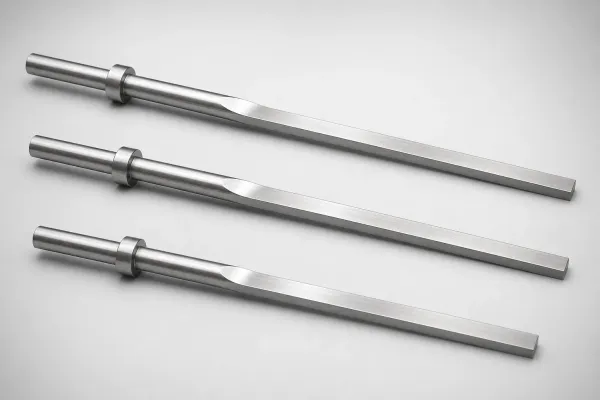
Standard ejector pins per DIN 1530 and JIS cover 1.0-25 mm diameters in stepped sizes. The smallest practical production pin is 1.0 mm. Smaller pins exist, and a 0.5 mm pin is a special for micro features. It bends easily, takes a shallow bore, and breaks under anything but light duty. Treat sub-1.0 mm pins as the exception that needs a documented reason.
Buckling sets the length limit. A loaded pin is a slender column. Unsupported length beyond about 20-25 times the diameter risks buckling before the part releases. A 3.0 mm pin stays safe to roughly 60-75 mm of unsupported length. A 1.0 mm pin is limited to about 20-25 mm, which is why tiny pins cannot reach deep into a tool.
The fix for a long reach is a stepped pin. The tip is ground small where it meets the part. The body carries a larger diameter, such as a 2.0 mm tip on a 6.0 mm body. The body keeps L/D low while the tip fits the rib. When even a stepped pin cannot stay under the limit, the ejector plate needs support bushings, or the feature needs another ejection method.
The diameter table below matches first-choice pin size to the push feature. It assumes the pin tip stays inside the feature width, which keeps the tip from straddling edges and carving a step into the wall.
| Push Feature | Wall or Land Width | First-Choice Pin Diameter | Design Note |
|---|---|---|---|
| Thin rib or wall | 1.0-1.5 mm | 1.0 mm | Smallest practical standard. 0.5 mm only for specials |
| Rib or boss land | 1.5-2.5 mm | 1.5-2.0 mm | Tip stays inside the feature width |
| Rib or boss land | 2.5-4.0 mm | 2.5-3.5 mm | Balance tip bearing against buckling reach |
| Boss or open land | 4.0 mm and up | 4.0-6.0 mm | Larger tip cuts bearing pressure on wide lands |
| Deep thin boss or rib | Any | Stepped or sleeve | Stepped pin or sleeve keeps L/D under 20-25 |
← swipe to scroll →
Table note: Diameter guidance follows typical DIN 1530 and JIS practice for pin ejection of ribs, bosses, and lands. Confirm with a bearing and buckling check for each pin.
Catalog standard pins carry most of this duty. Ejector pins from our standard ejector pin range cover 1.0-25 mm diameters with ground bodies.
The mold maker confirms body length, head diameter, and shoulder fit against the drawing before ordering. Length tolerance and head thickness matter as much as diameter. A long pin against a short plate leaves unsupported column, and a thin head pulls through under load.
Clearance, Fit and Steel
The pin slides in a bore through the core and the ejector plate, and that sliding interface is machined, not left to luck. Fit class, clearance, bore finish, and pin steel decide whether the pin moves freely for a million cycles or gall after a shift.
Fit class follows a standard pairing. The bore is reamed or jig-ground to H7, and the pin body is ground to g6. The g6/H7 pairing yields a sliding clearance of roughly 0.01-0.02 mm on common pin sizes, typical for ejector duty. Clearance below that risks binding when the mold reaches running temperature, and clearance much above it lets melt flash past the pin.
Bore finish matters as much as the number. A polished bore at Ra 0.2-0.4 µm typical keeps friction low and wear even. Reamed bores get that finish in one pass, and jig-ground bores hold it plus true position across the plate stack. Every bore must align with its counterpart in the ejector plate, because misalignment turns a free-sliding pin into a bending column.
Pin steel follows duty. Standard ejector pins run hardened to HRC 58-62, which resists wear and survives repeated impact against the part. Glass-filled resins change the rule, because compounds with 30% glass content are abrasive. TiN-coated pins add a hard surface layer, typically 2000+ HV, that survives the glass abrasion and extends pin life.
Pin tips meet the cavity face flush. A pin standing proud of the surface prints a raised ring on the part, and a recessed pin leaves a dimple that fills with melt. Typical flushness control lands at ±0.02-0.05 mm on the cavity face, measured at mold temperature for critical tools. The length grinding tolerance on the pin and the depth control of the counterbore together hold that number.
Lubrication is a maintenance topic, not a design cure. A correctly fitted g6/H7 pin with a polished bore runs dry for the life of most tools. Grease attracts debris, and debris gall the fit. When a pin starts to stick, check bore cleanliness, bore straightness, and plate alignment. Do that before any coating or lubricant decision.
Draft: The Real Force Lever
Draft is the cheapest force reducer in the tool, and it is decided before the ejector system exists. Every degree of draft on a core surface reduces the grip the ejection system has to overcome. Zero draft on a deep core is a force bill the pins pay for the life of the mold.
Typical practice holds 0.5-1° of draft per side on core surfaces for engineering parts, with polished steel taking the low end. Textured surfaces need more, commonly 1-2° per side, because the texture locks into the part. The draft angle is measured per side, so a box drawn with 1° per side tapers 2° across its width.
The force effect is steep, not linear. Molders treat 0.5-1° draft plus a polished core as cutting ejection force by up to roughly half on deep parts. That industry rule of thumb is verified at trial. Draft removes the grip progressively as the part strokes off the core, so release happens in stages instead of one full-width breakaway.
Draft and layout trade against each other. A part with good draft needs fewer pins and smaller tip area, because the force estimate drops with the friction it can deliver. A draft-poor part consumes pin area to buy back what geometry refused to give. When a deep rib or boss cannot take draft, stepped pins, sleeves, or a stripper compensate. Each option carries a cost the drawing should show.
The DFM review checks draft before any ejection math. A part model showing 0° on a 30 mm deep boss makes the force estimate fiction. The part must grow draft, or the tool must grow ejection hardware. That ordering is why draft decisions belong on the part drawing. Ejection decisions follow them in the mold layout.
Stroke, Return and Early Ejection
Force and area get the part off the core. Stroke gets it clear of the mold, and the return system gets the plate back before the next shot. Check all three against the press. A mold needing 120 mm of ejector stroke on a press offering 80 mm fails at installation, not at design.
Ejection stroke equals part depth plus clearance. The rule is part depth plus 5-10 mm, so a 40 mm deep housing needs 45-50 mm of stroke to clear the core completely. Shallow parts need less, but the clearance stays, because the part must fall or be gripped free of the mold face. Verify the total against the press ejector stroke, typically 30-150 mm on injection machines. Check the ejector force rating too, commonly a small share of clamp tonnage.
Early ejection changes how the stroke is used. On a typical sequence the mold opens 10-30 mm before the ejector advances. The part then leaves the core while still warm and compliant.
A warm part has lower modulus. It takes higher bearing stress at the pin tip without whitening, and it releases with less force. Early ejection is a sequence setting, but the mold enables it. Return springs hold the plate back during the open stroke, and the ejector timing is verified at the T1 trial.
The return system resets the plate. Return pins are the positive mechanism. They push the ejector plate back as the mold closes.
Springs hold the plate home between cycles, so pins stay retracted for automatic running. Return pins on small and mid-size tools commonly run 20-25 mm at the four corners, typical practice. Springs are sized for the moving mass. Spring life and preload follow the load and cycle math in our mold springs guide.
Skipping or undersizing the return system produces the ugliest failure in the catalog. If the ejector plate does not fully return before the mold closes, forward-returning cores, lifters, and slide inserts collide with extended ejector pins. The result is cracked inserts, bent pins, and a mold that opens with steel fragments in the cavity. Positive return pins prevent that collision by construction, and spring return keeps the plate parked during the open phase.
Ejection timing matters most on short programs. A 2-5 week tooling program has no schedule slack for a plate re-cut after a stuck-part trial.
Designing the stroke budget, return hardware, and early-ejection sequence before steel is ordered keeps a fast program fast. The trial then verifies numbers already closed on the drawing. A missing press data sheet turns every check into guesswork, and that is a DFM flag, not a detail.
Ejector System Design Checklist
Run the system through these checks before the ejector plate drawing is released. Each line ends in a number or a decision.
- Force estimate. Record F = p x A x friction with p from the material table and the friction coefficient at 0.1-0.3 typical. Note the value on the drawing.
- Tip area. Confirm combined pin-tip area lands near 1-3% of projected area for average parts, more on thin walls and deep cores. Divide F by the warm bearing limit to verify.
- Pin count. Convert area into pins at 1.0-6.0 mm diameter per the feature table. Use stepped pins for reach, sleeves for thin deep bosses.
- Layout. Place tips within 0.5-1.5 mm of walls or ribs. Keep the grid at 8-15 mm spacing. Keep every cosmetic face clear of tips.
- Diameter and length. Hold unsupported length under L/D 20-25 for every pin. Check each column, not just the longest one.
- Fit and finish. Specify g6 pin against H7 bore for 0.01-0.02 mm sliding clearance. Polish bores to Ra 0.2-0.4 µm typical.
- Steel and coating. Use HRC 58-62 pins as standard. Specify TiN coating when the resin carries glass fill.
- Draft. Confirm 0.5-1° per side on polished cores and 1-2° on textured surfaces before the force number is accepted.
- Stroke. Set stroke at part depth plus 5-10 mm. Confirm the press ejector stroke, typically 30-150 mm, covers it.
- Return. Size return pins and springs for the moving mass. Confirm full return before mold close so cores and lifters never meet extended pins.
- Sequence. Plan ejection to start at 10-30 mm of mold open. Verify the timing and the ejector force at the T1 trial.
FAQ: Ejector System Design
Q1. How do I estimate ejection force without a molding simulation?
Use the simple model F = p x A x friction coefficient. A is the projected area of the part over the core. p is the demolding pressure from the material family table. The friction coefficient runs 0.1-0.3 typical for polymer against polished steel. The result is accurate enough to size pin area, and the T1 reading of ejector pressure confirms it.
Q2. What pin diameter should I start with?
Start from the push feature, not from habit. A 1.0-1.5 mm wall takes a 1.0 mm pin, a 2.5-4.0 mm land takes 2.5-3.5 mm, and a wide boss takes 4.0-6.0 mm. Then check the column. Unsupported length must stay under L/D 20-25, and a long reach needs a stepped pin or a sleeve.
Q3. When do pins stop being enough?
When the required tip area exceeds what the geometry can host, or when the part is too thin to carry point loads. Walls under about 1.0 mm, deep thin bosses, and cosmetic faces that cannot accept a 0.025 mm witness all point past solid pins. The stripper comparison and the sleeve comparison articles cover those hand-offs in full.
Q4. My pin broke mid-run. Was that a design error?
Usually yes, and the design error is length, load, or alignment. A pin past its L/D 20-25 buckling limit fails under load. An oversized tip on a thin wall can push through, and misaligned bores bend the pin every stroke. Fit, flushness, and bore alignment are checked first, then load. Replacement follows the seven-step workflow in our broken pin guide.
Q5. Does early ejection really change the layout?
It reduces the force the layout must carry. Ejecting at 10-30 mm of mold open keeps the part warmer and softer. Bearing stress at the pin tips then stays below the whitening threshold with less tip area. It does not replace draft or correct a layout with pins on unsupported flats, but it can keep a marginal layout in service.
The Bottom Line
An ejector system is sized in five numbers: force, tip area, pin count, stroke, and clearance. Estimate the force from the resin, then convert it into tip area near 1-3% of projection. Place pins on supported geometry, check each column against buckling, and verify stroke and return against the press. Skip one number and the failure shows up at trial, where a 2-5 week program has no schedule left to absorb it.
DieStrike designs and builds ejection systems to this method under IATF 16949 across 120+ machines. Mold geometry holds ±0.005 mm, part geometry ±0.002 mm, and cavity steel runs HRC 62. Injection molds ship in 2-5 weeks and standard ejector pins in 3-7 days, for connector OEMs including TE Connectivity, Amphenol and Luxshare. Send your part drawing for a free 24-hour DFM review of its ejection layout.
KEEP READING
Related Reading
How to Prevent Ejector Pin Marks: 5 Root Causes and Fixes
Pin marks trace to ejection force, pin size, fit, and process. Five mold-side root causes with the fix order, from pin polish to packing pressure.
Read articleArticleHow to Choose Mold Springs by Life Cycle and Load
Spring life, load, and preload sizing for ejector return systems. Life classes from roughly 300,000 to 1,000,000+ cycles with selection math.
Read articleArticleHow to Replace a Broken Ejector Pin: 7 Steps
A broken pin costs production hours. Seven-step replacement workflow with fit checks, flush verification, and re-qualification after repair.
Read articleServiceMold Design & DFM
Free 24-hour DFM feedback on your part drawing: ejection layout review, force estimate, and manufacturability check before steel is ordered.
Read articleNEXT STEP
Ready to Start Your Mold?
Send us your element dimensions or part numbers — our team responds within 24 hours with pricing and lead time.

Written by
Ray ChanMold Buyer's Guide Author · Precision Mold Manufacturing Specialist. Ray helps global importers, distributors and OEMs source factory-direct molds and mold parts.