
How to Calculate Cooling Time for Injection Molding
Table of Contents
A converter quoted a 16 cavity housing tool at a 28 second cycle, then ran it at 41 seconds in the first production week. The cooling phase alone held at 31 seconds, and the shortfall was about 1,050 parts a shift against plan. Three inputs into one published equation predict that phase within about 15 percent of what the tool does.
This guide covers the equation, diffusivity by resin, the ejection threshold, cycle diagnosis, validation and the flow levers that move the number.
The Snapshot
- Cooling holds 50 to 70 percent of the cycle. On a 12 second clock that is 6 to 8.5 seconds, and one second removed from it returns about 8 percent more parts from the same press.
- Wall thickness is squared in the answer. A 2 mm polypropylene wall calculates to 1.6 seconds of cooling at a 60 °C mold, and a 3 mm wall to 3.7 seconds, which is 125 percent more time.
- Ejection lands at 60 to 80 percent of the melt-to-mold delta. Moving from 20 percent of the delta remaining to 40 percent cuts cooling time by 37 percent.
- Turbulent water starts near a Reynolds number of 10,000. A 12 mm channel needs about 5.7 L/min of 20 °C water, and every circuit should rise 3 to 5 °C from inlet to outlet.
The Cooling Time Equation and How to Read It
The working form for a flat wall is t = h2 / (pi2 x alpha) x ln[(4 / pi) x (Tmelt - Tmold) / (Teject - Tmold)]. h is the distance the heat travels in millimetres and alpha is the thermal diffusivity of the resin in square millimetres per second. The temperatures set the ejection threshold. This is the third equation in the calculation series, alongside clamp tonnage and tolerance stack-up.
Thickness sits outside the logarithm and is squared, so a wall 50 percent thicker needs 125 percent more cooling time. Temperature sits inside a logarithm and compresses: halving the gap between the ejection temperature and the mold temperature adds about 48 percent to the time.

Work a 2 mm polypropylene wall. Melt at 230 °C, mold at 60 °C, and a 170 °C delta released to 70 percent, so the part ejects at a mean temperature of 111 °C. The wall cools from both faces, so h is 1 mm, and alpha for polypropylene is 0.09 mm2/s. The logarithm term works out at 1.445, the coefficient at 1.126 seconds, and the cooling time at 1.63 seconds.
Treat 1.63 seconds as a floor. The equation assumes instant fill, perfect contact and constant properties, while a production cooling phase runs 1.4 to 2.5 times the calculated figure.
Read it backwards as a diagnostic. A 3 mm wall measuring an 8 second cooling phase against a calculated 3.7 seconds does not have a resin problem. It has channels too far from the surface, a laminar circuit, or scale in the water path.
Thermal Diffusivity Values by Resin
Thermal diffusivity is conductivity divided by the product of density and specific heat, which is why it carries units of area per time. Core grades of polypropylene, ABS, PA66 and polycarbonate sit in a narrow band.
| Resin | Thermal diffusivity (mm2/s) | Ideal cooling, 3 mm wall (s) | Note for the sheet |
|---|---|---|---|
| Polypropylene (PP) | 0.09 | 3.7 | Semi-crystalline, ejects warm but keeps shrinking after ejection |
| ABS | 0.09 | 3.7 | Amorphous, limited by stiffness rather than crystallization |
| PA66 (unfilled) | 0.10 | 3.3 | Moves heat faster, but needs a hot mold and dry resin |
| Polycarbonate (PC) | 0.11 | 3.0 | Fastest of the four, offset by a 90 to 120 °C mold requirement |
← swipe to scroll →
Table note: diffusivity values are typical published figures for unfilled grades, and cooling times are calculated at a 70 percent ejection fraction with a 170 °C melt-to-mold delta. Replace both with the grade datasheet and the mold temperature recorded at the trial.
Alpha sits in the denominator, so a 20 percent error in diffusivity is a 20 percent error in cooling time. The grade datasheet beats any refinement of the geometry model.

Filled and unfilled grades differ by 10 to 30 percent, and the direction depends on the filler system. Take the value from the grade the press will run.
Handbooks spread wider than datasheets: polypropylene appears from 0.08 to 0.15 mm2/s across sources. Fix one source, record it in the tool file, and stay with it.
Why Thickness Squared Dominates the Answer
Cooling time grows with the square of the distance heat has to travel, and walls are the hardest feature to change once a tool is cut. That is why the number belongs in design review rather than in the press setup sheet.
Hold the resin and the temperatures fixed and vary only the wall. The table uses polypropylene at 0.09 mm2/s, a 230 °C melt, a 60 °C mold and a 70 percent ejection fraction.
| Wall thickness (mm) | Distance h (mm) | Ideal cooling (s) | Index vs 2 mm wall |
|---|---|---|---|
| 1.0 | 0.50 | 0.41 | 0.25 |
| 1.5 | 0.75 | 0.92 | 0.56 |
| 2.0 | 1.00 | 1.63 | 1.00 |
| 2.5 | 1.25 | 2.54 | 1.56 |
| 3.0 | 1.50 | 3.66 | 2.25 |
| 4.0 | 2.00 | 6.51 | 4.00 |
← swipe to scroll →
Table note: ideal cooling times come from the equation above, with alpha at 0.09 mm2/s. Real cooling phases run 1.4 to 2.5 times these values on a production tool.
A 2 mm to 3 mm change adds 125 percent to the ideal cooling time, about 2 seconds on a 12 second cycle. On a production tool the same change costs 3 to 5 seconds, because the thicker wall also takes longer to fill and longer to pack.
Run the same test from 2 mm to 2.5 mm and the penalty falls to 56 percent. Wall reduction is the only lever that attacks the squared term; every other lever moves a coefficient by tens of percent.
Two features upset a single-wall calculation. A rib at 60 percent of the wall thickness freezes quickly on its own. The junction where it meets the wall carries the full wall thickness and cools last, so the rib root sets the cycle. A boss, a thread or a deep skirt behaves the same way, and a wall formed between a cooled core and an insert halves the path on each side.

Calculate per feature, then let the longest local time set the cycle.
Setting the Ejection Temperature
The equation needs an ejection temperature, and the reliable way to set one is as a fraction of the melt-to-mold delta. Field practice ejects a part once 60 to 80 percent of that delta has been released, which leaves 20 to 40 percent of the gap above the mold temperature at ejection.
For the polypropylene case, a 170 °C delta at a 0.7 fraction gives an ejection temperature of 111 °C. That fraction is the input most often set by habit, and moving it from 0.6 to 0.8 raises the calculated cooling time by 60 percent.
Two corrections matter. The equation works with the mean temperature through the wall, while a thermal camera reads the surface, which runs 10 to 25 °C cooler at ejection. And the fraction itself is set by stiffness at the press rather than by convenience on the sheet.
Amorphous resins are released when they are stiff enough near the heat deflection temperature. Semi-crystalline resins need enough crystallization first, or the part keeps shrinking after it leaves the tool, typically by 0.3 to 0.8 percent over the next 24 hours.
Mold temperature changes the answer only when the resin fixes the ejection temperature. On a polycarbonate part with a 130 °C ejection limit, moving the mold from 60 to 90 °C adds about 29 percent to the cooling time. That is the price of the flow and gloss it buys.
Why the Last 20 Percent of Cooling Costs the Most
The logarithm is what makes the end of the cooling phase expensive. Heat leaves a part in proportion to the temperature difference between the part and the steel, so each extra degree takes longer to remove than the degree before it.
The logarithm term is 1.158 with 40 percent of the delta remaining, 1.446 at 30 percent and 1.851 at 20 percent. Going from 40 percent remaining to 20 percent is 60 percent more cooling time. Pushing on to 10 percent takes the term to 2.544, which is 76 percent above the 30 percent case.
So ejecting at 40 percent of the delta remaining instead of 20 percent cuts cooling time by 37 percent, provided the part survives ejection without distortion or mark-off.
One second off a 12 second cycle is 8.3 percent more output: on a four cavity tool over an eight hour shift, 9,600 parts against 10,472. At a $45 an hour machine rate the saving is about $2,500 a year at 200,000 shots.
Where a part can be ejected warm, spend the money on handling instead of cooling. A conveyor that keeps the part flat for 30 to 60 seconds costs less than the press time it returns.
The full list of cycle levers lives in our guide to reducing injection cycle time, and this calculation sets their price. A change that trims 20 percent from the cooling phase is worth 10 to 14 percent of the total cycle where cooling holds half the clock.
Cooling-Limited, Pack-Limited or Plastication-Limited?
A cooling calculation is only useful when cooling is the binding constraint. Split the cycle on the machine timers first, because on a plastication-limited tool no amount of coolant flow shortens anything.
A 12 second cycle carries 0.5 to 1.0 second of fill and 1.5 to 2.5 seconds of hold overlapping the cooling timer. Cooling runs 6 to 8.5 seconds and mold open, eject and close take 2 to 4 seconds. Cooling holds 50 to 70 percent of the clock.
| Cycle limit | Test on the press | Reading | Where the fix belongs |
|---|---|---|---|
| Cooling limited | Cut 1 second from the cooling timer and inspect part 20 | Parts stick, warp or show ejector pull within three cycles | Channel layout, flow rate and turbulence |
| Pack limited | Add 1 second of hold time and weigh the parts | Weight still rising means the gate has not sealed | Gate size and hold profile, not cooling |
| Plastication limited | Compare screw recovery time with cooling time | 15 seconds of recovery against a 12 second cycle | Larger screw and barrel, or a smaller shot |
← swipe to scroll →
Table note: the three tests take about 20 minutes on a running press. Record the result against the tool number.
One measurement settles the first question. Change hold time in three steps and weigh the parts. If weight stays flat, the gate sealed early, extra hold buys nothing, and cooling is the limit.
Plastication is the limit more often than plants expect, and shot size as a percentage of barrel capacity is the first check. A 20 to 80 percent band is workable; above 80 percent, recovery time usually exceeds cooling time and the press sits closed waiting on the screw.
A cavity pressure trace separates the cases better than any timer. The point where the trace stops following the hold pressure is the gate seal, and the decay to zero after it is the real freeze time.
Validating the Number in the Mold
A calculated cooling time that never meets a press is a guess with decimals. Validation needs two instruments, and both cost less than a week of wrong cycle time on a running tool.
Cavity pressure is the reference. Place a sensor at the last point to fill and read three events. The fill peak, the point where the cavity trace stops following the hold pressure, and the decay of cavity pressure to zero. A part cannot be ejected while cavity pressure is above zero, so that decay is the real cooling floor.

A thermal camera covers the rest. Measure the part surface within 3 to 5 seconds of ejection, at three points per cavity. Aim for a cavity-to-cavity spread inside 5 °C; a spread above 10 °C points at a circuit imbalance, and a hot core side points at a missing bubbler or an uncooled slide.
Then compare the measured cooling phase with the sheet and work to ±15 percent per cavity. A bigger gap means an input is wrong: diffusivity from the wrong grade, a wall measured at a rib, or a mold temperature read at the controller instead of the cavity face.
Record the numbers in the tool file, because IATF 16949 process records expect a defined cycle and the evidence behind it.
Levers That Actually Move the Number
Six levers move a cooling number, and they do not carry equal weight.
- Wall thickness first. It is the only lever that changes the answer by a square. A 3 mm wall moved to 2.5 mm cuts ideal cooling time by 31 percent.
- Channel size, pitch and depth. Gun-drilled 12 mm channels on a 36 to 48 mm pitch, with centers 12 to 24 mm below the cavity surface, hold the surface ripple under about 5 °C. Our mold cooling channel design tips set the layout rules.
- Turbulent flow rather than more flow. A Reynolds number above 10,000 removes the laminar film that insulates the channel wall. A 12 mm circuit needs about 5.7 L/min of 20 °C water, a 10 mm circuit 4.7 L/min and an 8 mm circuit 3.8 L/min.
- Circuit count and inlet-to-outlet rise. Hold every circuit to a 3 to 5 °C rise. One series loop through four cavities leaves the last one 8 to 12 °C hotter, which adds 15 to 25 percent to cooling time on that cavity.
- Where steel beats water. A 12 mm channel 12 mm below the surface gives about 4,000 W/m2K on the water side and 2,400 W/m2K through the steel, a combined 1,500 W/m2K. A 0.3 mm scale layer at 1.5 W/m·K drops that to about 1,150 W/m2K, a 23 percent loss.
- Conformal cooling where drilling cannot reach. A printed insert at a constant 8 to 12 mm from the part removes the 25 to 30 mm drill path that sets the cycle on deep cores. Our conformal cooling guide covers the limits that apply.
Two smaller levers are worth knowing. Ejecting 10 points warmer on the delta, from 30 percent remaining to 40 percent, cuts cooling time by 20 percent and shifts the risk to post-mold shrinkage. Splitting one series circuit into parallel circuits changes nothing about flow rate and everything about cavity balance.

Every one of those levers sits in the tool rather than in the press. DieStrike supplies mold heating and cooling components, from baffles and bubblers to manifolds, fittings and controllers, so the circuit layout is settled while the tool design is still open.
When Inserts and Slides Change the Answer
A straight calculation assumes one steel path and one geometry. Inserts, slides and molded-in hardware break that assumption in three ways.
Material is the first. A copper alloy insert runs 105 to 200 W/m·K against about 29 W/m·K for P20, so it moves heat four to seven times faster and pulls the local cooling time down. Use it on a hot spot, never on a shut-off that has to hold a 0.005 mm clearance.
Moving steel without a circuit is the second. A slide or lifter often runs uncooled, and after 30 minutes its forming face sits 10 to 25 °C above the adjacent cavity steel. The wall it forms freezes last, worth 15 to 30 percent of local cooling time.
Thermal growth is the third. Steel expands at roughly 12 x 10-6 per °C. A 60 °C difference between a 300 mm slide and its pocket consumes about 0.22 mm of clearance, four times the 0.05 mm a slide normally runs.
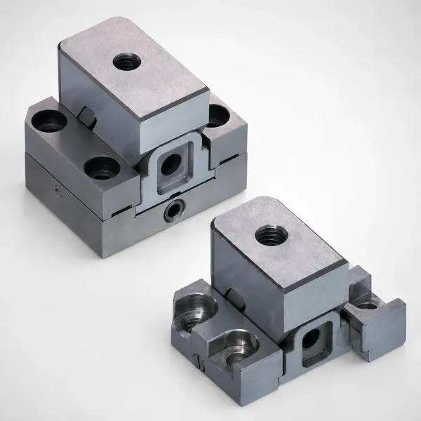
Molded-in hardware changes the packing rather than the water side. A cold insert absorbs heat from the melt, so the wall around it freezes earlier, local pack drops, and a sink can appear at the insert boundary. Calculate that wall with its own half thickness.
A Spreadsheet Workflow with Units
The arithmetic fits in one spreadsheet row per cavity, and one row per cavity is the only defensible layout.
- Wall thickness in millimetres, then the half thickness h. For a wall cooled from both faces, h is half the wall.
- Resin grade and thermal diffusivity alpha in square millimetres per second, taken from the grade datasheet.
- Melt temperature and mold temperature in °C, with the mold value read at the cavity face rather than at the controller.
- Ejection fraction f between 0.6 and 0.8, then the ejection temperature as Tmelt minus f multiplied by the melt-to-mold delta.
- The logarithm argument, which is 4 divided by pi, multiplied by the melt-to-mold delta divided by the ejection-to-mold delta.
- Cooling time in seconds, from the squared half thickness divided by pi squared times alpha, multiplied by the natural logarithm.
The spreadsheet form of the last line is =h^2/(PI()^2*alpha)*LN(4/PI()*(Tmelt-Tmold)/(Teject-Tmold)). The result is in seconds because square millimetres divided by square millimetres per second leaves seconds, and that check catches most sheet errors before they reach a quotation.
Two mistakes appear in almost every sheet. Using the full wall thickness instead of the half thickness multiplies the answer by four. Mixing centimetre and millimetre diffusivity makes it wrong by a factor of 100, since 0.09 mm2/s equals 0.0009 cm2/s.
Three more columns turn the sheet into a plan. Cooling should land between 50 and 70 percent of the target cycle. Heat load in kilowatts comes from shot weight and cycle time, so a 100 g shot on a 12 second cycle needs 2.2 kW removed continuously. Circuit flow for a 3 to 5 °C rise follows from that, and the same shot needs 7.8 L/min at a 4 °C rise before the turbulence requirement is met.
Keep a comparison column against the trial and hold each cavity to ±15 percent. Where a cavity misses by more, the sheet is usually right and the tool has a cooling fault.
Cooling Time Calculation FAQ
Q1. What is the cooling time formula for injection molding?
t = h2 / (pi2 x alpha) x ln[(4 / pi) x (Tmelt - Tmold) / (Teject - Tmold)]. h is the distance heat travels in millimetres, alpha is the resin diffusivity in square millimetres per second, and for a wall cooled from both faces h is half the wall.
Q2. Why does cooling time grow with thickness squared?
Heat has to travel from the centre of the wall to the steel, and the time scales with the square of that distance. A 2 mm polypropylene wall calculates to 1.6 seconds and a 3 mm wall to 3.7 seconds, an increase of 125 percent.
Q3. What ejection temperature should the calculation use?
Set it as a fraction of the melt-to-mold delta, ejecting after 60 to 80 percent of the delta has been released. A 230 °C melt and a 60 °C mold at a 0.7 fraction gives 111 °C, and moving that fraction from 0.6 to 0.8 changes the answer by 60 percent.
Q4. Which thermal diffusivity value belongs in the sheet?
Use the grade datasheet rather than a family average. Polypropylene and ABS sit near 0.09 mm2/s, PA66 near 0.10 and polycarbonate near 0.11 in typical published figures, and a 20 percent input error produces a 20 percent output error.
Q5. How do I know the cycle is cooling limited?
Change hold time in three steps and weigh the parts. Flat weight means the gate sealed early and cooling is the limit; recovery time longer than cooling time, or a shot above 80 percent of barrel capacity, means the press is plastication limited.
The Bottom Line
Cooling time is a calculation with three inputs and one exponent, and the exponent decides most of the answer. The time grows with the square of the wall, so a 2 mm to 3 mm change costs 125 percent more time.
Set the ejection fraction between 0.6 and 0.8 of the melt-to-mold delta. Hold each circuit to a 3 to 5 °C rise above a Reynolds number of 10,000, and prove the cavities match inside 5 °C. Recalculate per cavity, and check the sheet against the press within 15 percent.
DieStrike builds injection molds and stamping dies to IATF 16949, with ±0.005 mm mold accuracy and ±0.002 mm on EDM and jig-grinding work. Cavity heat treatment runs to HRC 62, the shop runs 120+ machines and serves tier-1 programs for TE, Amphenol, Luxshare and Dongshan. Standard components ship in 3 to 7 days and complete tools in 2 to 5 weeks.
KEEP READING
Related Reading
Mold Heating and Cooling Components
Baffles, bubblers, manifolds, hose fittings and temperature controllers specified with the circuit layout.
Read articleArticle5 Mold Cooling Channel Design Tips
Channel diameter, pitch and depth rules that decide how much of the calculated cooling time the tool can deliver.
Read articleArticleHow to Design Conformal Cooling Channels
When a printed insert beats gun-drilling, and the wall thickness and flow limits that apply.
Read articleServiceMold Trial and T1 Sampling
T0 and T1 trials with cavity pressure and thermal survey data, so the calculated cooling time is checked against the press.
Read articleNEXT STEP
Ready to Start Your Mold?
Send us your element dimensions or part numbers — our team responds within 24 hours with pricing and lead time.

Written by
Ray ChanMold Buyer's Guide Author · Precision Mold Manufacturing Specialist. Ray helps global importers, distributors and OEMs source factory-direct molds and mold parts.