
How to Design Stack Molds: Two-Level Tooling for High-Volume Parts
Table of Contents
A 600-ton press running a 16-cavity lid mold hits the tonnage wall before it hits the cycle time wall. The buyer doubles cavitation to 32 in the same footprint. Projected area doubles, and the parts now flash at 0.03 mm because the clamp cannot hold. The fix nobody priced in: a new 1,100-ton press, a heavier foundation and a $180,000 capital request. A stack mold avoids this trap entirely.
A two-level tool puts cavities on both faces of a center block. It produces 32 parts per cycle. It demands only about 50-60% of the clamp tonnage of a single-face 32-cavity mold. That is the core economics of stack tooling: double output without double tonnage.
Stack molds are also the most common source of synchronization failures we see in tooling reviews. If the center block drifts off mid-stroke by more than 0.05 mm, both parting levels flash at once. If the two ejection systems fire out of phase, parts weld to the wrong half and get crushed on close. This guide covers the mold-side decisions behind two-level tooling. Parting strategy, center block construction, center gating, opening stroke, ejection sync, tonnage math and the cost premium all get their own section.
The Snapshot
- A stack mold has 2 cavity parting levels and 3 plate interfaces. It roughly doubles output per cycle against a single-face mold of the same footprint.
- Required clamp tonnage drops 40-60% versus a single-face mold of equal cavitation. Opposing projected areas cancel across the center block.
- Total mold opening stroke is about 2x a single-face mold for the same demolding clearance. Press daylight must be checked before the design freezes.
- Stack molds cost 40-80% more than equivalent single-face tooling and add 1-3 weeks to lead time (typical industry figures).
- Center block position must stay within ±0.05 mm of true mid-stroke to avoid two-level flash. Rack-and-pinion or harmonic synchronizers are the standard fix.
Stack Mold Basics: How Two-Level Parting Works
A single-face mold opens at one parting line. A stack mold opens at two parting lines at the same time, on two levels stacked behind each other in the clamp direction. The fixed half carries a cavity plate.
The moving half carries another cavity plate. Between them sits the center block, a double-sided plate with cores on both faces. Each level forms one complete set of parts.
The parting sequence has three interfaces. Interface 1 opens between the fixed cavity plate and the front face of the center block. Interface 2 opens between the rear face of the center block and the moving cavity plate. Interface 3 is not a parting line at all: it is the sprue entry on the fixed platen, where melt enters the mold. Both parting levels must open in the same ratio, at the same time, or one level will pull parts off its intended side.
Think of a stack mold as two molds sharing one clamp unit and one injection unit. The two-level parting concept extends the plate structures you may already know. Our two-plate vs three-plate molds guide explains how plate count controls runner separation in single-level tools.
Stack molds take the plate logic one step further. The center block behaves like a floating B plate on one side. On the other side it acts as a floating A plate.

Why the center block floats. Nothing on the press holds the center block. It moves only when the two parting levels drag it along through mechanical synchronizers, or when lift cylinders carry it. In a balanced design, the center block stays at the exact midpoint of the opening stroke. Both levels then open equally.
Mid-stroke position tolerance is typically held to ±0.05 mm. Beyond that, one level opens early. Parts stick to the wrong side, and the closing mold crushes them.
When Stack Molds Win: Thin-Wall, High-Volume Parts
Stack molds are not a universal upgrade. They win in a specific band of part geometry and volume. The sweet spot is large projected area, thin walls, shallow draw depth and annual volumes above roughly 5 million parts.
The parts that fit best. Pails from 0.5 to 2.0 L, lids at 0.4-1.2 mm wall, trays, shallow automotive interior panels and thin decorative bezels all share one trait. Projected area per part is big while draw depth is small.
Big projected area is exactly what eats clamp tonnage. A 200 mm diameter lid at 480 bar cavity pressure needs about 140 tons of clamp in a single cavity. Stack the same lid two levels deep and the second level's tonnage cancels the first.
The volume math. A stack mold adds 40-80% to tooling cost. That premium only pays back when the extra output per hour is worth the capital. A typical breakeven frame helps.
If a two-level mold raises output 80-95% per cycle, payback improves sharply. Run 4,000+ hours per year for 3 years and payback usually lands inside 18 months. Below 1 million parts per year, a single-face multi-cavity mold is almost always cheaper overall.
When stack molds lose. Deep-draw parts over about 100 mm tall fail the opening stroke test. Two levels need double daylight, and most 500-800 ton presses run out of stroke. Family molds with unbalanced fill are poor candidates.
Balancing two levels at once doubles the tuning work. Low-volume programs under 500,000 parts per year cannot amortize the premium. Parts with heavy side-actions on both faces complicate the center block beyond reason.
Stack Mold vs Single-Face Multi-Cavity Tooling
The real decision is stack mold versus a single-face mold with the same total cavitation. The table below compares a 2x16 stack mold against a 32-cavity single-face mold for a 200 mm lid, using typical industry figures.
| Factor | 2-Level Stack Mold (2x16) | Single-Face Mold (32 Cav) |
|---|---|---|
| Required clamp tonnage | About 1,100-1,300 tons | About 2,200-2,400 tons |
| Press size class | 600-800 ton machine usable | 1,300+ ton machine required |
| Opening stroke demand | 2x single-level stroke | 1x stroke |
| Tool cost (typical) | +40-80% vs single-face | Baseline |
| Mold thickness | +120-250 mm (center block stack) | Baseline |
| Fill balance risk | Two levels must match within 5% | One plane, easier to balance |
| Maintenance complexity | Higher: synchronizers, dual ejection | Lower: one parting line |
← swipe to scroll →
Table note: Figures are typical industry values for a 200 mm PP lid at 0.5 mm wall. Actual tonnage depends on cavity pressure and projected area.
How to read the table. The stack mold trades tool cost for press cost. If the molder already owns a 1,300-ton press with free capacity, the single-face mold usually wins on total cost of ownership. If the only free press is 650 tons, the stack mold is the only way to run 32 cavities at all. The tonnage reduction logic gets its own section below because it is the single most misunderstood part of stack mold design.
Center Block Design: Cavities on Both Sides
The center block is the heart of a stack mold and the reason the tool costs 40-80% more. It is a thick, double-sided plate that carries cores on both faces and a hot runner manifold through its middle. Getting it right is a steel, stiffness and thermal problem at the same time.
Thickness and stiffness. Center blocks typically run 100-160 mm thick for lid-class tools. Injection pressure pushes the two cavity sets away from each other at up to 480 bar cavity pressure.
Without support, the block bows in the middle and the parts flash at the parting line. Support pillars or hardened pads under the core plates limit deflection to about 0.02 mm per 300 mm of span. That is the common mold design target.
Steel selection. The block body is usually P20 pre-hardened at HRC 28-32 for machinability. The cavity and core inserts on both faces go to through-hardened H13 or S136 at HRC 48-52. Critical wear surfaces reach HRC 62 in our tooling programs.
Insert construction matters more than ever here. A center block with 32 machined-in cavities is scrap if one cavity wears out. Thirty-two replaceable inserts keep repair cost at a few hundred dollars per position.
Two-sided symmetry. The front and rear faces of the center block must be machined from the same datum. The two faces must be parallel within 0.01-0.02 mm across the full block. Any wedge error between the faces shows up as uneven part thickness on one level only.
That is the signature defect of a badly built stack mold. At DieStrike, key mold dimensions are held to ±0.005 mm and component geometry to ±0.002 mm. Two-sided center block work demands exactly that level of control.

Thermal management inside the block. The center block has no room for lazy cooling. Both faces generate heat. The hot runner manifold in the middle adds more. Cooling channels typically sit 15-25 mm below each face at 8-10 mm diameter.
The two circuits must be balanced so both levels cool at the same rate. Uneven cooling causes one level to hold parts longer. That breaks ejection sync. Many programs put conformal channels in the center block inserts for exactly this reason.
Weight and handling. A 16+16 stack center block assembly can weigh 2-4 tons. That weight changes mold base selection, crane capacity and platen loading.
The platen deflection check is mandatory. A 650-ton press with 1,200 mm tie-bar spacing may show 0.05-0.10 mm bow under a concentrated 3-ton mold. That is enough to steal parting-line contact pressure at the block corners.
Center Gating: Hot Runner Manifold Through the Center Block
Melt reaches a stack mold from one direction only: through the fixed platen. From there it must feed two levels of cavities that sit on opposite sides of a solid steel block. Cold runners are effectively excluded from production stack molds.
Runner volume and the ejection of solid sprues across two levels make them impractical above about 8 total cavities. Nearly every stack mold built today is hot runner fed. The melt path runs down the mold centerline.
The center sprue path. The machine nozzle seats on a sprue bushing at the fixed platen. A center-fed hot runner main manifold sits in or above the center block. Drop nozzles branch to both faces. Half point toward the fixed-side cavities, half toward the moving-side cavities.
For a 2x16 lid mold, one manifold feeds 32 nozzles through a two-level distribution tree. If you are new to manifold selection, our hot runner vs cold runner comparison covers the baseline trade-offs. A stack mold pushes them to the extreme.
Flow balance between levels. This is the hardest fill problem in stack tooling. The two levels should fill within 5% of each other by weight. Otherwise one level packs while the other short-shots. Balance comes from mirrored manifold branches, equal-length flow paths to every gate and consistent tip thermal control.
Mold flow analysis pays for itself here. A fill study at the design stage typically costs $1,500-4,000. Rebalancing a manifold after assembly costs 10-20x that in machining and downtime.
Thermal growth of the manifold. A hot runner manifold in a stack mold runs at 200-300 °C for PP and up to 320 °C for engineering resins. The surrounding center block sits near 20-80 °C. The manifold grows thermally by 0.3-1.0 mm along its length depending on size.
Nozzle tip positions and manifold supports must be designed around the hot dimension, not the cold one. Tip-to-gate contact that is perfect at room temperature can leak or crush at operating temperature. Designers must dimension for the hot state.
Valve gates versus thermal gates. Most high-volume stack molds use valve gates driven by pneumatic or hydraulic cylinders, sequenced by the press. Valve gates give a clean gate witness. They allow sequential fill control across the two levels and cut stringing risk during mold opening. Thermal gates survive only in small-part molds under about 10 mm projected size, where gate cosmetics do not matter.
Service access. The manifold sits in the least accessible location in the mold: buried between two cavity sets, with drops pointing both directions. Specify heater cartridge redundancy, thermocouple breakout to an exterior junction box and pull-back clearance for nozzle seals. A tip seal failure that requires splitting the entire stack costs a full production day. A design with serviceable drops costs an hour.
Opening Stroke and Two-Sided Ejection Sync
A stack mold needs twice the opening stroke of a single-face mold to demold the same part. Each level must open far enough for parts to clear the cores, plus robot access clearance. For a 30 mm tall lid with 15 mm ejection clearance per level, a single-face mold needs about 45 mm of useful stroke. The same mold built as a two-level stack needs roughly 90-120 mm total opening.
Both levels open at once, and each adds its own clearance. On a press with 600 mm daylight and a 380 mm mold, a 120 mm stack stroke can exhaust the open distance. Always run the stroke budget before the design freeze, not after.
Synchronizing the two parting levels. Both levels must open and close in a fixed ratio, ideally 1:1. Three mechanisms do this job. Rack-and-pinion synchronizers use a center gear keyed to the center block. Two racks on the fixed and moving halves mechanically force equal travel.
Harmonic gear synchronizers use three meshing gears to split the stroke equally. Lift-cylinder designs use hydraulic cylinders tied to the press. They carry the center block to mid-position. Rack-and-pinion remains the most common choice for tools up to about 1.5 tons of center mass.
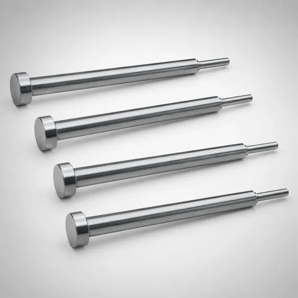
Two-sided ejection. Parts form on both faces of the center block. Both levels therefore need their own ejection system. The moving-side ejector plate runs off the standard press knockout. The fixed side and the center-block faces need secondary actuation.
Options are mechanical straps tied to the opening motion, mold-mounted hydraulic cylinders or synchronizer-driven puller plates. On both levels, ejection must fire within a few milliseconds of each other. It must complete before mold closing starts.
Why phase errors destroy parts. If the front level ejects and the rear level holds, parts remain on the center block. The press then closes on a half-empty mold. The next shot packs extra material into occupied cavities. It flashes both levels and can damage cores.
Return pins with early-return switches are standard protection on production stack molds. So are cavity presence sensors on at least one level per side. Ejector stroke per level typically runs 15-30 mm for shallow parts and 40-60 mm for deep containers.
Ejector system sizing. Each level carries half the total cavitation. Ejector pin count per face therefore matches a single-face mold of equal cavitation, and the same selection rules apply. Pin sizing, blade selection and ejection force calculations from standard multi-cavity practice carry over to each level.
Clamp Tonnage Math: Why Projected Area Cancels Out
The tonnage saving is the entire business case for a stack mold. The physics is simple. Clamp tonnage equals projected area times cavity pressure. Projected area acts like a vector. Melt pushing the fixed half away from the mold also pushes the moving half the other way.
The cancellation. In a single-face 32-cavity lid mold, all 32 cavities push in one direction. Projected area is 32 x about 314 cm² for a 200 mm lid, roughly 10,050 cm². At 400 bar average cavity pressure, that is about 2,400 tons of separating force. In a 2x16 stack mold, the 16 front cavities push toward the moving platen.
The 16 rear cavities push toward the fixed platen. The center block absorbs both loads internally. The press clamp sees only the imbalance plus friction losses, typically 50-60% of the single-face figure. That is about 1,100-1,400 tons for the same 32 parts per shot.
It is not free. The cancellation is not perfect. The hot runner manifold pressure at the center adds separating force at the fixed-side interface. Friction in the guide system transfers part of the load to the platens.
Any imbalance in cavity count, projected area or fill pressure between levels leaks through to the clamp as real tonnage. That is why designers keep both levels identical in projected area within 2-3%. Mold flow analysis then confirms fill pressure symmetry.
Practical sizing rule. Size the press for 1.2-1.3x the calculated net separating force, as you would for a single-face mold. Then verify against the press tie-bar spacing and platen deflection. The full calculation method, including cavity pressure factors by material, is in our clamp tonnage guide.
One extra check for stacks. For stack molds, add one verification step. Confirm the tonnage number at the highest planned injection pressure, because a 10% drift toward faster fill can raise cavity pressure by 40-60 bar.
Mold Base, Guide System and Center Block Alignment
A stack mold is taller, heavier and more alignment-sensitive than any single-face mold of equal cavitation. The mold base and guide system carry the center block through millions of open-close cycles. Positional repeatability is measured in hundredths of a millimeter.
Guide pillar selection. Standard leader pins at 0.02-0.04 mm clearance are not enough to register the center block. Production stack molds use precision ground guide pillars with 0.005-0.015 mm running clearance. Interlocking taper locks or cone locks register the center block interfaces. The taper locks carry lateral injection loads.
The guide pillars only locate and never fight pressure. Lock sizing follows the same rules as any precision multi-cavity tool. Engagement depth should be at least 2x the lock width.
Center block registration. The block needs positive location at full close, not just guidance during travel. Common practice is four corner wear plates plus a center cone or taper lock pair. Shut-off faces are lapped so parting-line contact is even within 0.01 mm. If the block shifts 0.10 mm laterally during injection, every part on both levels shows a step mismatch at the parting line.
Stack height and press fit. The added center block stack increases shut height by 120-250 mm. Check three press limits before ordering steel. First, minimum mold height with the ejector knockout engaged.
Second, maximum daylight minus the full stack stroke. Third, platen load capacity for the concentrated mold weight. A mold that fits on paper can still fail if the knockout length does not reach the deeper moving-side ejector plate.
Cost and Lead Time: The 40-80% Stack Mold Premium
Stack mold pricing surprises many buyers. Cavitation only doubles, yet the price can nearly double too. The premium is real, and it comes from five places in the bill of materials.
Where the money goes. First, the center block itself. A thick, double-sided plate with two full insert sets adds 25-35% to steel and machining content versus a single-face mold of equal cavitation. Second, the hot runner. A center-fed two-level manifold with double the drops typically costs 40-60% more than a single-level manifold of the same nozzle count.
Third, synchronizers. A rack-and-pinion or harmonic set for a production mold runs roughly $3,000-12,000 depending on size. Fourth, the second ejection system with its own actuation and sensors. Fifth, extra design and mold flow work. Fill balance across two levels needs simulation, and design hours grow 30-50%.
Lead time impact. A single-face 32-cavity lid mold typically ships in 8-12 weeks. The equivalent stack mold adds 1-3 weeks for center block machining from two datums, manifold fitting and synchronization trial. At DieStrike, injection mold lead times run 2-5 weeks for standard tool classes, with DFM feedback inside 24 hours.
Stack configurations are quoted case by case, because center block and hot runner scope varies widely. When you compare quotes, insist that every line item is broken out separately. Steel grade per component, hot runner nozzle count, synchronizer type and surface treatment let two bids be compared like for like.
Stack Mold Failure Modes and How to Design Them Out
Stack molds fail in characteristic ways. Each failure mode below maps to a specific design countermeasure. All five show up in first-off samples if the tool was never simulated and trial-verified.
Two-level flash from center block drift. The center block does not hold mid-stroke position. One parting level closes tighter than the other, and flash appears on both levels at once. Countermeasure: rack-and-pinion synchronizers with hardened racks, plus taper lock registration at full close. Monitor flash at 0.02 mm as the trip limit during mold trial.
Level-to-level fill imbalance. One level short-shots while the other flashes at the same process settings. Root cause is almost always unequal flow length in the manifold branches or unequal gate sizes. Countermeasure: mirrored manifold geometry, gate-to-gate fill weight checks within 5% at mold trial, plus valve gate sequencing if imbalance persists.
Parts stuck on the wrong face. Ejection on one level fires late or a puller plate fails. Parts then stay on the center block during closing. Countermeasure: part presence sensors on both levels, early-return verification of all ejector plates and draft angles of at least 1° per side on textured surfaces.
Center block bow under pressure. Flash appears only at the middle of long parting lines. That is the classic sign of block deflection. Countermeasure: support pillars sized for 0.02 mm deflection per 300 mm span. Verify by structural analysis at 480 bar cavity pressure.
Hot runner leaks inside the block. A tip seal fails. Melt migrates into the center block cavity pockets and freezes components in place. Countermeasure: manifold supports designed at hot dimensions, spare seal kits staged at the press and heater current monitoring to catch thermal drift early.
A 7-point hot runner check before every run applies directly to every stack mold. Cover heaters, thermocouples, tip seals, manifold torque, gate condition, hose routing and controller zones.
Stack Mold Design Checklist: 12 Points Before You Cut Steel
Use this checklist at design review. Every item has killed a stack mold program when skipped.
- Press daylight budget: max daylight minus mold shut height leaves at least 2x the per-level demolding stroke plus 50 mm robot clearance.
- Projected area symmetry between the two levels within 2-3%, confirmed by model measurement not estimate.
- Net separating force calculated with 1.2-1.3x safety factor and cross-checked against the actual press at maximum injection pressure.
- Center block thickness verified for 0.02 mm deflection per 300 mm span at full cavity pressure.
- Center block steel: P20 body at HRC 28-32 minimum, replaceable cavity and core inserts hardened to HRC 48-62 by function.
- Both block faces machined from one datum, parallel within 0.01-0.02 mm.
- Synchronizer type selected and rated for the center mass: rack-and-pinion, harmonic gear or lift cylinders.
- Hot runner manifold layout mirrored between levels, with fill weight balance target within 5% and mold flow sign-off.
- Nozzle tip and manifold supports dimensioned at operating temperature (200-320 °C melt range), not cold.
- Dual ejection systems with independent actuation, phase-matched within milliseconds and proven with early-return switches.
- Cooling circuits per level balanced for equal cycle time, with channels 15-25 mm below each face.
- Service plan: drop seal access, heater redundancy, thermocouple breakout and spare parts list staged before T0.
At T0 trial, run the same verification ladder as any multi-cavity tool. Check fill balance shots, flash limits at 0.02 mm and dimensional reports per level, then capability before sign-off. Our mold trial guide covers the T0 to first-article sequence that stack molds also follow.
Stack Mold FAQ
Q1. How much clamp tonnage does a stack mold really save?
Typically 40-60% versus a single-face mold of equal cavitation. The opposing projected areas of the two levels cancel across the center block. The press clamp only sees imbalance and friction losses. For a 32-cavity 200 mm lid program, that means roughly 1,100-1,400 tons instead of 2,200-2,400 tons (typical figures at 400 bar cavity pressure).
Q2. How much more does a stack mold cost?
A 40-80% premium over an equivalent single-face mold is the typical range. The extra cost concentrates in four areas. The center block needs double-sided machining and two insert sets.
The two-level manifold costs 40-60% more than a single-level unit. Synchronizers add $3,000-12,000, and the second ejection system adds its own actuation cost. Lead time grows by 1-3 weeks.
Q3. What parts are good candidates for a stack mold?
Thin-wall, large-area, shallow-draw parts at high volume. Lids and closures at 0.4-1.2 mm wall, pails from 0.5 to 2.0 L, trays and automotive interior panels all fit. The program should run above roughly 5 million parts per year to amortize the tooling premium. Deep parts over about 100 mm draw usually fail the press daylight check first.
Q4. Why do stack molds need a hot runner instead of a cold runner?
Cold runners are impractical above about 8 total cavities. The sprue and runner system must eject from two parting levels while the mold splits at three interfaces. A center-fed hot runner manifold drops to both faces and keeps material waste near zero. That matters when a lid program runs 50-100 million shots.
Q5. What is the most common stack mold failure at trial?
Two-level flash caused by the center block drifting more than ±0.05 mm off mid-stroke position. The second most common is level-to-level fill imbalance over the 5% weight tolerance. Asymmetric manifold branches or unequal gate sizes are the usual causes. Both are designed out with proper synchronizers and mold flow analysis. T0 fill weight checks per level verify the fix.
The Bottom Line
Stack molds double output per cycle and cut required clamp tonnage 40-60%. But center block drift beyond ±0.05 mm flashes both parting levels at once. For thin-wall, high-volume parts, the trade wins. DieStrike builds IATF 16949 precision tooling at ±0.005 mm mold accuracy with 24-hour DFM feedback.
If your program volume justifies two-level tooling, send us the part data for a stack-versus-single-face comparison at our contact page.
KEEP READING
Related Reading
How to Design Two-Shot Molds
Two-level parting, rotating cores and material pairings explained for multi-shot tooling programs.
Read articleArticleTwo-Plate vs Three-Plate Molds
Plate count drives runner separation, parting sequence and cost. Compare the two classic mold structures.
Read articleArticleHow to Calculate Clamp Tonnage
Projected area times cavity pressure sets the tonnage. See the math before you size the press.
Read articleServiceInjection Mold Manufacturing
IATF 16949 injection mold building with ±0.005 mm accuracy and 2-5 week lead times.
Read articleNEXT STEP
Ready to Start Your Mold?
Send us your element dimensions or part numbers — our team responds within 24 hours with pricing and lead time.

Written by
Ray ChanMold Buyer's Guide Author · Precision Mold Manufacturing Specialist. Ray helps global importers, distributors and OEMs source factory-direct molds and mold parts.