
How to Design Two-Shot Molds: 2K Tooling, Sequences and Cost | DieStrike
Table of Contents
A buyer approved a two-shot housing with a 1.2 mm TPE gasket over a PC frame. The tool quote came back at 2.1x the price of the single-shot version. At T1 the second shot flashed under the gasket lip on 60 percent of the parts. Three weeks of steel rework followed before one cavity ran clean. Every failure traced back to tool architecture decisions made before the RFQ.
Two-shot molding, also called 2K molding, is a family of tool architectures. Each one molds a second material onto a first-shot part inside one machine cycle. The tool carries the cost and the risk. A two-shot mold typically prices at 1.5-2.5x an equivalent single-shot tool, typical industry figures. The premium buys rotating platens, retracting cores, two runner systems, and seal-off geometry that a normal tool never needs.
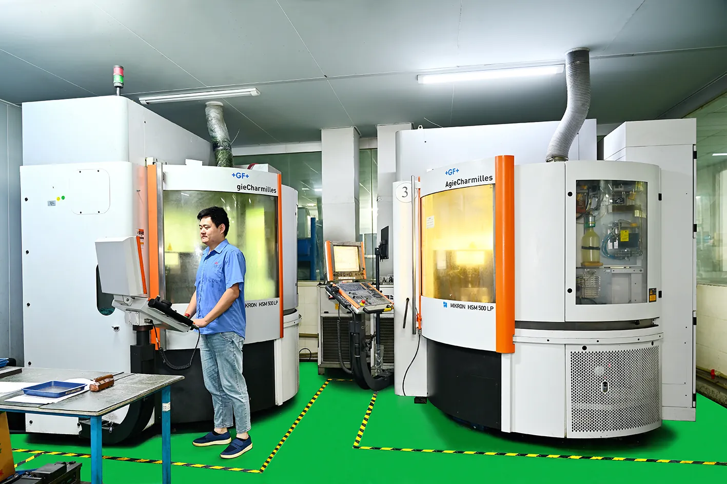
This guide is written from the mold maker's side of the table. DieStrike operates under IATF 16949 across 120+ machines. Mold size precision holds to ±0.005 mm, with critical geometry at ±0.002 mm. Injection mold lead time runs 2-4 weeks. Those facts matter here because every rule below is checked at the DFM stage, before steel is ordered.
The Snapshot
- A rotary platen tool indexes the core half 180 degrees per cycle. Index repeatability holds near ±0.01 mm with taper locks.
- A core back tool retracts steel 0.5-3.0 mm to open the second-shot cavity, adding 2-5 seconds of in-tool motion per cycle.
- Two-shot mold prices typically run 1.5-2.5x a single-shot tool, before cavity count and mechanism are added.
- Second-shot vent depth follows the overmold resin: 0.01-0.03 mm for crystalline grades, 0.03-0.05 mm for amorphous grades, typical practice.
- Shrinkage mismatch between pair materials runs 0.3-2.0 percent typical, and the substrate wall should hold at least 50 percent of the total stack.
What Two-Shot Molding Is: A Tooling View
Two-shot molding runs two different materials through one tool so they come out bonded in a single cycle. The first shot forms a rigid substrate. The second shot adds a soft layer, a seal, a color, or a second rigid material. Second-shot walls commonly run 0.5-3.0 mm, and the interface between the two materials stays inside the tool for the whole cycle.
Three tool architectures dominate. A rotary platen tool uses two cavity stations set 180 degrees apart. A core back tool retracts steel to open the second-shot space. A pick-and-place cell moves the substrate into a second mold with a robot. Each one changes the mold drawing, the steel count, and the price differently.
The shared feature is sequencing. The first-shot part becomes an insert inside the tool for the second shot. Every 2K mold must locate that part precisely, protect it from melt pressure, and eject it after the second material cools. Interface tolerances between the two shots typically run ±0.05-0.10 mm.
Buyers evaluate a two-shot mold on three numbers first. These are the cost premium of 1.5-2.5x, the cycle effect of the index or transfer step, and the scrap risk at the material interface. The rest of this article gives the thresholds behind each one.
Material Pairs and Bonding
The material pair sets the tool design more than any other input. Two bond mechanisms exist in practice. A chemical bond welds the two melts together when the polymer backbones are compatible. A mechanical bond locks the second material into steel-cut undercuts when chemistry will not help. Roughly 60-70 percent of commercial soft-touch overmolds rely on chemical welding, typical practice.
Compatible pairs weld during molding. TPE-S over PP bonds because both share an olefin backbone. TPV over PP behaves the same way. TPU over PC and over ABS welds on polar surfaces, which is why the pair shows up in consumer electronics housings and wearables. For olefin pairs the substrate face must stay near 130-160°C at contact, so the second-station steel often runs 30-50°C hotter than the first.
Incompatible pairs need steel geometry. TPE over nylon, over POM, and over most glass-filled grades will not weld. Automotive connector housings with TPE seals therefore rely on full mechanical locks instead of chemistry. Anchor undercuts of 0.3-0.8 mm are typical, and the anchor area should cover the shear path, not just the peel face. Through-holes of 1-2 mm let the second material wrap through and form a rivet, which is the strongest mechanical option.
Bond quality is verified at T1, not assumed. Peel tests run at 90 degrees with a pull rate near 50 mm/min. Soft-touch pairs commonly pass at 2-6 N/mm when failure is cohesive and rubber stays on the substrate, typical acceptance. Adhesive failure at the interface sends the design back to the material pair or the anchor geometry.
| Material pair | Bond mechanism | Typical mold-side requirement | Common parts |
|---|---|---|---|
| TPE-S (SEBS) over PP | Chemical olefin weld | Second-station steel 30-50°C hotter, with anchor undercuts of 0.2-0.5 mm optional | Power tool grips, handles, gaskets |
| TPV over PP | Chemical olefin weld | Seal-off lands 1.5-3.0 mm wide around the substrate edge | Interior trim, sealing boots, air ducts |
| TPE-S over ABS or PC/ABS | Partial chemical plus mechanical | Mechanical keys plus 30-50 µm face texture, with second melt kept below ABS distortion | Keypads, buttons, handheld housings |
| TPU over PC | Chemical polar weld | Gates away from thin PC walls, with bond area at least 40 percent of the contact face | Phone cases, wearable housings |
| TPE over PA or POM | None, mechanical only | Full lock: undercuts of 0.3-0.8 mm or through-holes of 1-2 mm | Seals over glass-filled frames, strain reliefs |
← swipe to scroll →
Note: bond ratings and anchor sizes are typical guidance from published overmolding practice. Confirm each pair against grade-specific datasheets before the RFQ.
The bonded face needs a defined finish. Molders often texture the substrate face with 30-50 µm deep erosion to widen the weld area and hide surface variation. Texture also masks the shrink step that shows at the material transition. The texture spec belongs on the mold drawing, because adding it after T1 means reworking the cavity insert.
Second-shot gates should sit over the thickest supported substrate wall. The melt then wets the bond face before it freezes, instead of washing the substrate out of position. Thin unsupported walls of 1.0-1.5 mm deflect under second-shot pressure, and a deflected wall moves the seal line with it.
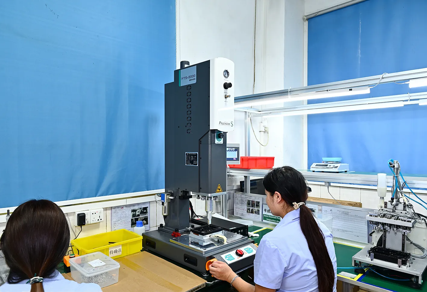
If a pair fails bond qualification and volume stays low, teams often fall back to assembly joining. Ultrasonic welding of a soft layer needs an energy director 0.3-0.5 mm tall on the rigid face. That geometry must be on the original mold drawing, because it cannot be added to steel later without a new insert. Adhesive bonding needs a 0.1-0.3 mm bond-line gap planned into the same drawing.
Tool Architecture: Rotary Platen
A rotary platen mold splits the fixed half into two cavity stations set 180 degrees apart. The core half rides on a rotating plate. Station A molds the substrate. The plate turns and carries that substrate to station B, where the second cavity closes over it and molds the second shot.
Both stations work in every cycle. Station A forms the next substrate while station B completes the previous part. One finished part leaves per index. A typical 180 degree index adds 0.8-1.5 seconds per cycle, industry figures.
Positioning decides quality. The core must land under cavity B in the same spot every cycle. Index systems use taper locks and locating rings, and repeatability holds near ±0.01 mm in a fresh tool. When wear pushes that past ±0.03 mm, the second-shot wall varies and a visible step appears at the material transition.
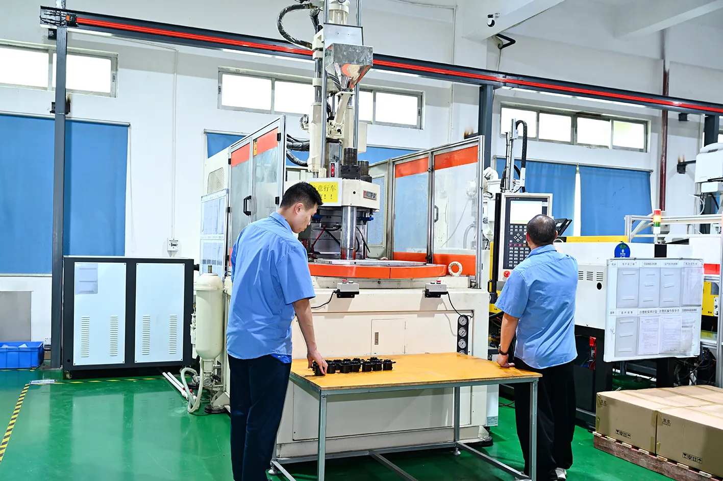
The tool footprint grows with the two stations. A rotary base typically runs 30-60 percent larger than its single-shot equivalent. It carries two cavity insert sets, two runner systems, and separate cooling circuits per station. Steel volume and machining hours scale with that geometry, which is the first line of the cost premium.
Each station needs its own temperature control. Station A cools the substrate below its distortion point before the index. Station B holds the steel window that keeps the bond face alive. Station A and station B circuits are sized independently, and their steel temperatures can differ by 30-50°C on one tool.
Tool Architecture: Core Back
A core back tool keeps the part on one core and creates the second cavity by moving steel. After shot 1, a core retracts or a slide pulls back to open a space 0.5-3.0 mm deep around the substrate. Shot 2 fills that space. The part never leaves the core, so the concentricity between the two materials is set by steel, not by handling.
The retract motion must repeat. Hydraulic cylinders, angle pins, or the ejector system drive the moving steel, and it returns to the same stop every cycle. Return position repeatability near ±0.01-0.02 mm is required, because the motion sets the second-shot wall thickness. Locking wedges hold the core against injection pressure during shot 2.
Core back costs cycle time. Retract, fill, and return typically add 2-5 seconds versus a fixed-core tool, industry figures. The penalty is acceptable when rotation accuracy or part handling would cost more in scrap.
Edge gaskets and sealing lips are classic core back geometry. Second-shot walls of 0.5-1.5 mm run along the perimeter of the substrate, and the retracting core forms the space behind the lip. A housing rim of 2-3 mm wall gains a 1.0-1.5 mm seal lip without a second machine or a robot.

The crowded B side is the price. A retracting core removes steel from a zone that also needs cooling channels and ejectors. Designers resolve the conflict by moving the second-shot cavity toward the parting line, which is why core back tools often show a second parting line on the drawing. Ejector stroke typically grows 20-40 percent versus the single-shot layout.
Tool Architecture: Pick-and-Place
Pick-and-place is two molds and a robot instead of one complex tool. Shot 1 runs in a conventional mold. A robot lifts the substrate and loads it into a second mold that adds the second material. The substrate arrives as an insert, exactly like a metal insert in a normal overmold tool. Tooling spend lands near the sum of two single-shot molds, typically 1.8-2.4x one tool, before automation.
The molds stay simple, and that is the point. Both tools use standard single-shot architecture with normal side actions and ejection. The second mold needs a locating nest cut to the substrate geometry. Nest clearance typically runs 0.05-0.15 mm per side so the part drops in without sticking.
The nest carries the position tolerance, not the robot. Robot repeatability runs ±0.02-0.05 mm typical, and vision systems correct drift toward ±0.01 mm. The nest is machined to the substrate datums, and seating sensors verify the part before the mold closes. A part seated 0.1 mm off shifts the seal line and the wall thickness together.
The second-shot gate must not blow the substrate off its nest. Mold designers place the gate opposite the locating features so melt pressure pushes the part into the nest. Support steel behind thin substrate walls is cut into the B side, because a 1.0 mm wall deflects under typical cavity pressures of 30-60 MPa.
The economics flip with volume. Parallel presses can outproduce a rotary tool when substrate and overmold cycles differ. Below roughly 100,000 parts per year, two standard molds plus a robot often beat one 2K tool on total program cost, typical break-even ranges.
Shot-to-Shot Isolation: Sealing and Flash Control
The second cavity seals against a plastic part, not against steel. That is the central difficulty of 2K tooling. Second-shot cavity pressure typically reaches 30-80 MPa near the gate. Melt at that pressure finds any gap under the substrate edge. Flash there is material that has flowed between the two shots, and it destroys the interface.
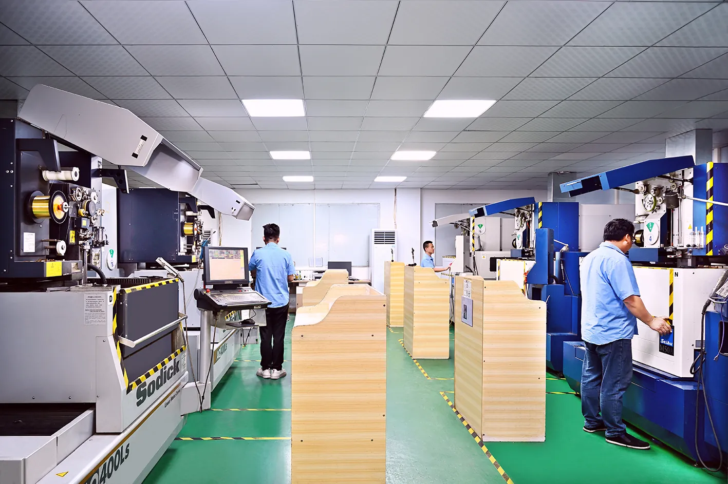
Seal strategy one is steel-to-steel shut-off. The second cavity lands on machined steel lands around the substrate edge, 1.5-3.0 mm wide. The substrate stays fully supported by the core beneath it. The shut-off line is wire-EDM cut and lapped, then verified at T1.
Seal strategy two is a controlled crush bead. A 0.3-0.5 mm tall bead molded on the substrate edge crushes 0.05-0.15 mm when cavity B closes. The crush absorbs steel tolerance and part shrink variation. Below 0.05 mm of crush the seal leaks, and above 0.15 mm the bead tears during demolding.
Never seal plastic against a sharp steel corner. The closing cavity would shave or deflect the substrate edge. Chamfer the cavity lead-in 0.2-0.5 mm and give the substrate edge a matching radius. The cavity then slides over the part instead of hitting it.
Write the flash limit into the RFQ. Visible flash at the material interface is rejected above 0.05 mm on most parts, and functional seals allow less. The mold design and DFM review maps every escape path: under the substrate, around ejector pin gaps, and along the second parting line.
Shrinkage Mismatch and Warpage
The two materials shrink at different rates, and one mold must compensate for both. Mold shrinkage spans 0.3-2.0 percent across common thermoplastics. Amorphous resins sit low, with ABS at 0.4-0.7 percent and PC at 0.5-0.7 percent. Crystalline resins sit high, with PP at 1.5-2.0 percent. The difference between the pair is the design problem.
The first shot shrinks before the second shot exists. The substrate is at final size when shot 2 wraps around it. As the second layer cools it contracts against a rigid substrate, and the differential strain bows the pair. A 0.5 percent mismatch across a 150 mm panel can lift the free edge 0.3-0.6 mm in molded trials, which fails flatness and seal specs.
| Resin | Family | Typical mold shrinkage | Role in a 2K pair |
|---|---|---|---|
| PP | Crystalline | 1.5-2.0 percent | Substrate under TPE-S grips, where high shrink drives cavity A compensation |
| ABS | Amorphous | 0.4-0.7 percent | Substrate for keypads and soft-touch electronics |
| PC | Amorphous | 0.5-0.7 percent | Rigid frame under TPU bumpers and seals |
| TPE-S (SEBS) | Block copolymer | 1.0-2.0 percent by grade hardness | Soft layer over PP, where the wetting window drives station B steel |
| TPV | Partially crystalline | 1.2-1.8 percent | Soft layer over PP for interior trim and seals |
← swipe to scroll →
Note: percentages are typical published datasheet ranges and shift with grade, hardness, and wall thickness.
Cavity compensation treats each shot separately. Cavity A is sized for the substrate resin shrinkage alone. Cavity B adds the second-shot wall plus a small allowance for the pull of the cooling second layer. Mold makers commonly start with 10-30 percent of the second resin shrinkage added to that allowance, then adjust from T1 measurements.
Wall ratio dominates warpage. Keep the first-shot wall at roughly 50 percent or more of the total stack. A 2.5 mm soft layer over a 1.0 mm substrate warps far more than the reverse, because the cooling soft layer has no rigid partner. Thick soft sections also sink, and sink depth scales with soft wall thickness.
Cooling symmetry locks the flatness in. Both faces of the composite should cool at similar rates. Core and cavity circuits at the second station should hold steel temperature within 5-10°C of each other. Asymmetric cooling turns a balanced shrink pair into a warped one.
Gate and Runner Strategy for Each Shot
Two independent runner systems live in one 2K mold. Shot 1 feeds the substrate cavity, and shot 2 feeds the second cavity. They never share a manifold. A rotary tool can carry four to eight drops across its two stations on an automotive-size part, typical.
The shot 1 gate hides under the second material or is cut away. Gate marks show through a translucent overmold, so the substrate gate goes on a face that shot 2 covers. Tunnel gates of 0.8-2.0 mm diameter are the standard answer on covered faces, typical by resin.
The shot 2 gate must not hammer the substrate. Direct impingement can wash a thin wall out of position before the cavity fills. Fan and tab gates spread the melt over a wide land. Tab width typically runs 60-100 percent of the local wall width, and the gate sits over the thickest supported section.
Weld lines belong away from seal faces. When shot 2 flows around the substrate from two sides, the flows meet in a weld line on the far side. A weld line in TPE-S can drop to 50-80 percent of bulk strength, so the meeting point should sit off the sealing lip. The vent goes at that last fill point.
Runner type follows volume. Valve-gated hot runners keep shot 1 molten between cycles and remove sprue handling from the index. Each drop adds a heater and thermocouple zone to the drawing. Second-shot volume often runs 10-30 percent of the total part, which is why cold sprue systems stay common when the second shot is small.
Venting and Cooling for 2K Tools
Venting in a 2K tool has two jobs. The first is normal cavity venting for each shot. The second is evacuating air trapped between the substrate and the second cavity. A sealed pocket can scorch the substrate face within 1-2 trial shots.
Vent depth follows the second resin. Crystalline grades run 0.01-0.03 mm deep, and amorphous grades 0.03-0.05 mm, typical practice. Vents are cut on steel-to-steel lands only. Where steel meets the substrate face there is no room for a vent, so the designer routes the last fill to a land that can carry one.
Deep pockets may need vacuum venting. A vacuum system pulls air for 0.5-1.0 second before shot 2 closes. Without it, a closed pocket behind the substrate compresses and burns before the melt reaches the far side.
Cooling is zoned per station and per half. Station A chills the substrate so it survives the index. Station B holds the higher steel window that the bond needs. Each circuit is sized independently, with channels 8-12 mm in diameter spaced 2-2.5 channel diameters from the cavity wall.
Balance is measured, not assumed. Flow between parallel circuits should hold within ±10 percent, and steel temperature across a station within ±5°C, typical T1 acceptance. The temperature map is re-checked after 10,000 cycles, because index motion wears seals and shifts flow.
Cost Drivers and Budget Ranges
Price the architecture, not the part. A two-shot mold typically lands at 1.5-2.5x the price of a single-shot tool for the same part, typical industry figures. Most 2K tools run one or two cavities, because each added cavity doubles the insert sets, the index load, and the cooling work.
The premium comes from five line items. Two cavity insert sets replace one. A rotary base runs 30-60 percent larger. A second runner system adds its own heating and control. Independent cooling circuits per station and 40-80 percent more DFM hours close the list, typical.
| Cost driver | Typical effect vs single-shot tool | What raises it further |
|---|---|---|
| Cavity insert sets | Two sets instead of one | Bond-critical finishes, face texture on the substrate insert |
| Mold base footprint | +30-60 percent for rotary platen | Index drive hardware, larger plates |
| Second runner system | +15-30 percent tooling work | Valve gates, extra control zones per drop |
| Mechanism | Rotary index, core back, or robot nest | Repeatability spec tighter than ±0.01 mm |
| Cooling circuits | +40-80 percent channel work | Separate temperature windows per station |
| DFM and T1 sampling | 40-80 percent more engineering hours | Two material lots, bond and seal testing |
← swipe to scroll →
Note: percentages are typical comparisons for similar part size and cavity count. They are not DieStrike price quotes.
Scrap risk is a cost driver too. A rejected second shot usually costs the substrate with it. Tryout scrap of 5-15 percent at T1 is common for new 2K tools, typical industry experience. A design that shortens bond and seal debugging is worth more than the steel it saves.
Ask for the architecture recommendation, not a menu price. The quote should split the premium by insert sets, base, runner system, mechanism, and trials. DieStrike returns DFM feedback within 24 hours and a cost breakdown within 48 hours on submitted part data.
Budget for the pair, not the tool. Two material qualifications and cycle trials at the molder sit outside the mold price. Plan 10-20 percent of the tool value for program-level debugging beyond quoted T1 sampling, typical.
Design Review Checklist Before RFQ
Run this list before the RFQ leaves your desk. Every item is a number the mold maker can check in the first DFM pass. Items that fail here become rework after steel is ordered. A 2K insert rework typically costs 20-40 percent of the tool price when it happens after hardening, typical.
| Check | Threshold to hold | Failure mode if missed |
|---|---|---|
| Material pair bond data | Peel spec at 90 degrees, 50 mm/min, 2-6 N/mm for soft-touch pairs | Interface delamination at T1 |
| Bond anchors | Non-bonding pairs: undercuts of 0.3-0.8 mm or through-holes of 1-2 mm | Layer separation in service |
| Wall ratio | First-shot wall at least 50 percent of the total stack | Warpage and edge curl |
| Shrinkage data | Grade ranges: PP 1.5-2.0, ABS 0.4-0.7, PC 0.5-0.7 percent | Cavities cut to the wrong size |
| Draft on second-shot faces | 1-3 degrees per side, never below 1 degree | Drag marks and ejection damage |
| Interface tolerances | Interface dimensions owned by one shot, ±0.05-0.10 mm | Step mismatch and flash |
| Gate vestige locations | Shot 1 gate under covered faces only | Marks show through the overmold |
| Trial plan | Two material lots, shot-1-only sampling first | Wrong root cause at T1 |
← swipe to scroll →
Note: thresholds are typical starting points. The mold maker should confirm each one against the specific grades in the RFQ.
The DFM report should return each row marked pass or risk. Read the risk rows before you compare prices, because they are the difference between a 2-week trial and a 6-week one, typical spread.
Two documents belong with the RFQ. The first is the part model with the material pair named on the drawing. The second is the bond test record or the datasheet peel data. Mold makers quote 2K work from those two inputs. A missing bond record typically adds a 5-10 percent contingency to the quote.
Frequently Asked Questions
Q1. How does a 2K mold price compare with two single-shot molds?
A single two-shot tool typically runs 1.5-2.5x the price of one single-shot mold for the same part. Two single-shot molds plus pick-and-place automation land near 1.8-2.4x and need two machines and floor space. The rotary tool wins on footprint and handling consistency. The two-mold route wins on flexibility when either shot changes independently.
Q2. Which materials bond without mechanical locks?
Pairs that weld chemically: TPE-S over PP, TPV over PP, and TPU over PC or ABS. None of them bond if the substrate face is cold at contact, which is why the second-station steel window matters as much as the chemistry. Olefin pairs typically need the face near 130-160°C, and peel passes commonly land at 2-6 N/mm.
Q3. Why does a 2K tool need two cooling circuits?
The two stations answer different questions. Station A cools the substrate below its distortion point before the index, and station B holds the bond window. Steel temperatures on one tool can differ by 30-50°C between stations. A single shared circuit cannot serve both without forcing a compromise in one of them.
Q4. When should I choose core back over rotary platen?
Choose core back when the part must stay on one core, the geometry lets steel retract 0.5-3.0 mm, and the cycle can absorb 2-5 seconds of in-tool motion. Choose rotary when the second layer covers a large area and the 0.8-1.5 second index is the cheaper trade. Pick-and-place fits low volume or very different cycle times between the two shots.
The Bottom Line
Two-shot molds price at 1.5-2.5x a single-shot tool and fail on interfaces, not on injection. Pick the architecture, seal the interface, and compensate shrink before steel is cut. DieStrike reviews designs under IATF 16949 across 120+ machines, with DFM feedback in 24 hours.
Send the part model and the material pair to DieStrike's mold design DFM review before the RFQ goes out, and first feedback lands within 24 hours.
KEEP READING
Related Reading
How to Balance Multi-Cavity Molds: Runner, Gate and Cooling
Runner balance holds cavity weight variation within 1-2 percent, the same discipline that keeps a two-shot interface even.
Read articleArticleHot Runner vs Cold Runner: Which Is Right for Your Mold?
Hot runner systems add $8,000-$20,000 to a tool but cut cycle 15-30 percent, a trade-off every 2K runner plan faces.
Read articleArticleHow to Design Undercuts for Automotive Parts
Automotive undercuts add $3,000-$15,000 per side, and side action travel must clear the locked depth plus 2-3 mm.
Read articleArticleHow to Design Snap Fits for Injection Molded Parts
Snap-fit beams work within 1-2 percent strain limits, which sets latch length, draft, and the mold features behind them.
Read articleNEXT STEP
Ready to Start Your Mold?
Send us your element dimensions or part numbers — our team responds within 24 hours with pricing and lead time.

Written by
Ray ChanMold Buyer's Guide Author · Precision Mold Manufacturing Specialist. Ray helps global importers, distributors and OEMs source factory-direct molds and mold parts.