
How to Design Molds for Consumer Electronics Housings
Table of Contents
A 0.9 mm charging case shell failed its cosmetic audit at 68 percent first-pass yield. The 0.09 mm gate vestige sat 5 mm from the LED window on the class A face. Re-polishing that insert cost $2,400 and added 6 days to the schedule. The geometry decision that caused the rework was made 9 weeks earlier, at the gate layout review.
Consumer electronics housings punish molds harder than most automotive parts of the same size. Wall thickness runs 0.8 to 1.2 mm, and class A and class B cosmetics cover 80 percent of the visible area. Annual volumes push tooling to 4 to 16 cavities with hot runner systems. Device and connector OEMs including TE Connectivity, Amphenol and Luxshare run precision programs in this class. DieStrike, an IATF 16949 mold maker with 120-plus machines, sees the same geometry failures repeat every quarter.
Every rule below chains into one housing main line. Gate placement must feed 0.8 to 1.2 mm walls, and cavity finish must survive high-volume runs. Texture hides what polish cannot. Figures are typical industry values unless tied to DieStrike tooling practice.
The Snapshot
- Walls run 0.8 to 1.2 mm typical for PC/ABS, and one gate feeds only 60 to 90 mm of flow at that thickness.
- Gate vestige target is 0.05 to 0.1 mm on class A shells, always placed on an inner wall or hidden edge.
- Textured areas need 1 degree of base draft plus roughly 1 degree more per 25 µm of texture depth, a typical rule of thumb.
- Rib bases run 50 to 60 percent of wall thickness, or 0.45 to 0.55 mm on a 0.9 mm shell.
- DieStrike hardens cavity inserts to HRC 62 with ±0.005 mm mold accuracy, and DFM feedback lands within 24 hours.
Wall Thickness and Flow Length: The 0.8 to 1.2 mm Budget
Wall thickness is the first number the mold designer locks, because it fixes flow length, gate count and cooling time in one decision. Thin-wall shells sit at 0.8 to 1.2 mm typical for PC/ABS. A phone mid-frame runs 0.8 to 0.9 mm, and a charging case runs 0.9 to 1.1 mm. A laptop deck runs 1.2 to 1.5 mm. Below 0.8 mm, fill pressure passes 1,000 bar typical and the machine choice changes.
Flow length decides gate count, not part length. At 1.0 mm PC/ABS, a single gate fills 60 to 90 mm of flow in a normal processing window. A 160 mm housing needs two gates or a film gate. Ratio math helps: a flow to wall ratio above 100 starts thin-wall rules. Ratios past 150 force high-speed machines running 600 to 1,200 mm/s injection rates.
Wall uniformity matters more than the average number. A step from 1.2 to 0.9 mm inside a battery pocket creates a packing gradient. That gradient shows as 0.05 to 0.15 mm sink on the show face. Taper thickness transitions at 2:1 to 3:1 over 5 to 10 mm of run. Cooling time scales with the square of wall thickness, so 1.0 to 0.8 mm cuts cooling by roughly 36 percent.
Thin walls also set the clamp tonnage on the press. Cavity pressure at 1.0 mm wall runs 500 to 900 bar typical. A 100 cm² housing then projects 55 to 95 tonnes of clamp force. Check that number against the machine before the mold base is cut.
| Wall thickness | Typical materials | Gate recommendation |
|---|---|---|
| 0.8 to 1.0 mm | PC/ABS, PC or ABS thin-wall grades | Film gate, or 2 to 3 hidden pin gates. A single gate is risky above 60 mm flow. |
| 1.0 to 1.2 mm | PC/ABS, PC, ABS | Fan or submarine gate at 1 to 2 points on the inner wall. |
| 1.2 to 1.5 mm | PC/ABS, ABS, 10 to 20 percent GF-PC frames | Edge gate acceptable. Vestige of 0.1 to 0.3 mm hides under a lip. |
| 1.5 to 2.5 mm | 30 percent GF-PC and GF-PA brackets | Standard tunnel or edge gate. Weld line placement is less critical. |
← swipe to scroll →
Table note: Typical industry guidance for PC/ABS and ABS shells. Confirm gate count with mold flow analysis and the material data sheet.
Gate Scheme for Class A Shells: Count, Position and Vestige
A class A housing has no acceptable gate location on its show face. The gate scheme therefore starts from the B side geometry. Film gates at 0.5 to 0.8 mm thickness spread melt along a 30 to 60 mm edge. Pin gates at 0.6 to 1.2 mm diameter suit shorter flows. Submarine gates shear their own vestige on ejection, so they dominate hidden edge locations.
Vestige height is a drawing number, not a hope. Consumer OEMs commonly spec 0.05 to 0.1 mm residual for hidden gates. Marks under an inner lip can run 0.1 to 0.3 mm. Grinding a gate witness to that band costs 1 to 2 bench hours per cavity. At $40 to $80 per hour typical, gate position quietly decides part of the mold price.

Gate freeze timing sets the packing window. At 0.8 to 1.2 mm wall and 60 to 90 °C mold temperature, a 0.7 mm gate freezes in 2 to 5 seconds typical. That freeze caps pack time before part weight stabilizes. Gate land adds pressure, so keep land at 0.8 to 1.5 mm. Long land at thin wall is a shear heater that shifts gloss unevenly.
Every runner branch ends in a cold slug well. The well traps the 5 to 10 mm plug of cooled melt that fires first. Without it, the plug stalls the front and marks the gate area. A 3 to 5 mm deep well with 6 to 10 mm diameter is typical for housing gates.
Weld Lines and Melt Merge Points: The Geometry Fix Comes First
Every hole and every melt split creates a weld line. A speaker grille with 12 holes makes 12 pairs of fronts that re-merge around each opening. Merge position is set by gate layout and wall thickness. A thickness step of 0.2 mm can move a merge point 10 to 20 mm downstream.
Weld strength is the structural risk. Unfilled PC/ABS weld lines retain roughly 60 to 90 percent of bulk strength in typical audits. A 30 percent glass-filled grade can drop below 50 percent at the same location. Parts that carry load across a weld need the merge moved or the grade changed before tooling starts.
Mold-side fixes come first in review order. Rebalance gate distances so fronts meet inside a hidden boss area. Add 0.3 mm flow leaders along ribs to steer the front. Vent the merge zone with 0.02 to 0.04 mm deep channels typical for PC/ABS. High injection speed narrows the visible knit line, but speed is a process layer, not a geometry fix.
Cosmetic weld lines have one more hiding place. A logo pad, a recessed brand area or a gasket seat can absorb the merge. Many shell drawings show a 0.2 to 0.5 mm step at these zones. That step lets the front meet in a shadowed corner that never sees direct light.
Ejector Marks and Function Markings: Design the B Side Like the A Side
Ejector witness on class A shells is avoided by design, never by process adjustment. Pins press on the B surface, so a visible mark means the force path distorted the wall. A 3 to 6 mm pin spread across a rib base keeps local stress under 30 MPa typical. That check runs at 60 to 90 °C ejection temperature.
Count and position follow the ribs and bosses, not the flat floor. A 120 by 70 mm shell typically carries 8 to 20 ejectors. Tip mismatch sits at 0.02 to 0.05 mm after spotting. Blades replace round pins on 1.0 mm ribs. Stepped ejectors reach the deepest battery pocket without piercing the show face.

Textured surfaces forgive more witness. That is why B-side texture specs exist. A VDI 24 class surface hides a 0.05 mm pin ring that an SPI B2 polish would show. When ejector marks still appear on a gloss part, the fix is usually a larger pad, not a slower cycle.
Texture and Draft Arithmetic: What the Grain Costs the Wall
Texture sells the product, but it taxes the mold. A housing specified SPI C1 or VDI 24 has a 20 to 40 µm class surface depth. That depth drags against ejection. Base draft on textured walls moves from 1 degree up to 2 to 3 degrees typical.
Use a practical rule of thumb: add roughly 1 degree of draft for every 25 µm of texture depth. A 35 µm grain then needs about 2.4 degrees total. Measure depth from the photo-etched sample the mold shop quotes against. Grain depth varies by etch batch, so the part drawing is not the reference.
Texture stops where steel seals. Keep a 3 to 5 mm polished band at the parting line, shut-offs and gate areas. A textured shut-off face traps flash at 0.02 to 0.05 mm. That flash fails cosmetic audit even when the function is acceptable.
Steel and Cavity Finish for Cosmetic Shells
Cosmetic shells make steel choice a finish and corrosion decision, not a strength one. High gloss piano black parts run S136 ESR or NAK80 cavities. Both polish toward SPI A1 at a 0.01 to 0.02 µm Ra class. Painted or matte housings tolerate 718H at 30 to 36 HRC with far lower material cost.
Hardness protects the gloss face over volume. Polished steel below 46 HRC scratches during handling. Wear lines appear after 100,000 to 300,000 cycles typical at that hardness. DieStrike hardens production cavity inserts to HRC 62. High-gloss faces then hold polish through high-volume runs at ±0.005 mm mold accuracy and ±0.002 mm part geometry.
Flame-retardant grades attack steel. PC/ABS with FR additives releases acidic species at molding temperature. Stainless or passivated cavity surfaces outlast P20 tooling in the same program. Corrosion pitting that starts at 0.02 mm depth shows as haze on a gloss part within weeks.
Verify the gloss on the bench, not on the press. A 60 degree gloss meter reads 85 to 95 GU on a true piano black cavity. Below 80 GU, the polish step or the steel is wrong. Respotting a gloss cavity takes 2 to 4 hours and must happen before texturing.
Glass-Filled Structural Parts: Shrinkage, Orientation and Wear
Internal frames and brackets carry the drop loads. They run glass-filled grades where 30 percent GF is the common spec. Molded shrinkage for 30 percent GF PC runs 0.3 to 0.5 percent typical. Unfilled PC/ABS runs 0.5 to 0.7 percent. That range shifts every cavity dimension by 0.003 to 0.005 mm per 10 mm of feature.
Glass orients along flow, so shrinkage is anisotropic. Along-flow shrinkage can sit at 0.2 to 0.3 percent. Cross-flow runs 0.4 to 0.6 percent in the same part. That split bows flat frames 0.1 to 0.3 mm unless gating is symmetric. Mirror gates on both ends of a bracket cancel most of the bow.

Process inputs stack on top of geometry. Mold temperature, pack profile and injection speed all bend glass orientation. Our guide to avoiding warpage in thin-wall molds covers the process side in depth. Run the first trial with the cavity gates open on both ends.
Abrasion is the tool wear story. A 30 percent GF melt erodes gate edges and sharp corners. Structural cavities run at 48 to 62 HRC with nitrided gates typical. Weld lines in glass-filled parts hold only 30 to 50 percent of bulk strength. Keep load paths off any knit line.
Ribs, Bosses and Snap Fits at Shell Scale
Rib thickness on a shell follows one ratio: 50 to 60 percent of the local wall. On a 0.9 mm wall that is 0.45 to 0.55 mm at the base. The rib tapers to 0.3 mm at the tip. Fatter ribs pull sink marks through the show face at 0.05 to 0.15 mm depth. Texture cannot fully hide that sink.
Bosses follow the same logic. A screw boss on a 1.0 mm shell carries 0.5 to 0.7 mm walls. Keep outer to inner diameter near 2:1 minimum to avoid sink. Gussets of 0.4 mm tie the boss to the wall. Typical retention tests show 30 to 50 percent more pull-out stiffness with gussets.
Snap fits get their own numbers at this scale. The full snap fit design rules apply with shell values. Beam thickness runs 0.6 to 0.8 mm on unfilled PC/ABS. Latch deflection is 0.4 to 0.8 mm typical. Strain should stay under 2 to 4 percent for repeated assembly.
The snap undercut of 0.3 to 0.5 mm decides lifter versus side action. That choice also sets mold price, so review it early. Screw bosses carry another tolerance: inner diameter at ±0.05 mm typical for self-tapping assembly. Holding that bore depends on the core pin finish and the shrinkage compensation.
Side Actions, Lifters and the Undercut Budget
USB ports, button holes and latch windows demand moving steel. A side core with 3 to 8 mm travel covers most connector pockets. Lifters handle 0.3 to 1.5 mm internal undercuts at 5 to 12 degree angles. Typical lifter travel stays inside 8 to 15 mm.
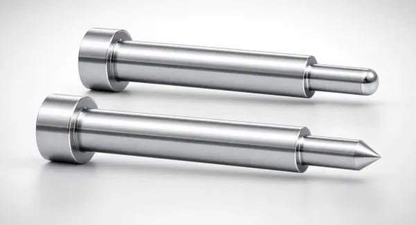
Every action adds a wear interface and a failure mode. Slides run on hardened wear plates with 0.02 to 0.05 mm clearance typical. Return springs are sized at 30 to 50 percent over-travel. Cooling must route around the pocket without starving it. DieStrike builds these actions in house, and standard components such as ejector pins, core pins and springs ship within 3 to 7 days.

Budget the actions early. A single side core adds $3,000 to $8,000 typical to mold price. Each lifter adds another $1,500 to $4,000. When the undercut exists only for assembly, a 0.3 mm draft change can remove the action. A two-piece part is the second escape route.
Cooling Layout and Cycle Time for Thin Walls
Cooling owns the cycle in thin-wall shells. A 1.0 mm PC/ABS wall cools in roughly 8 to 15 seconds to safe ejection. That is 60 to 70 percent of a total 20 to 35 second cycle typical. Channel placement decides both time and warpage.
Keep cooling channels 2 to 3 hole diameters from the cavity surface. That classic rule still holds. A 10 mm channel placed 20 to 30 mm from the steel face removes heat evenly. A 20 mm gap leaves a hot spot that sinks the wall 0.05 to 0.1 mm. Fountains and baffles reach boss towers and button pockets that straight drilling cannot touch.
Zone balance matters at gloss level. Adjacent zones held within 5 °C prevent the 0.03 to 0.08 mm steps that appear as gloss bands. Mold temperature controllers for PC/ABS shells typically run 60 to 90 °C. High-gloss PC parts run 80 to 110 °C.
Hot runner systems change the cooling math. They remove the cold runner mass from every cycle. A 4-cavity housing tool with a hot runner cuts 5 to 10 seconds per cycle typical versus a cold runner. That gain pays the manifold cost inside the first production year.
Multi-Cavity Layout and Quick Change Tooling
Volume sets cavity count before steel is ordered. A 100,000 to 300,000 unit year typically runs 2+2 tooling. A 300,000 to 800,000 unit year runs 4+4. Above 1 million units, the tool moves to 8 to 16 cavities with hot runner systems. Cavity count multiplies gate, vent and cooling complexity together.
Balance is the whole game past two cavities. Runner lengths to each cavity should match within 5 percent typical. Family cavities, such as left and right shell halves, must fill from identical gate distances. Otherwise one half packs short. Balance checks at trial run the same cycle on every cavity before approval.
Quick change keeps one base serving many programs. A standardized insert pocket system swaps a housing cavity in 30 to 60 minutes. A common mold base lets a spare insert cover a running program. Housing molds commonly land on 3535, 4040 or 4545 metric base classes. Shared base geometry lets the shop pre-order the frame and springs.
DieStrike quotes injection molds at 2 to 5 weeks lead time. DFM feedback arrives in 24 hours. A cavity revision then fits inside the original schedule window. Standard mold components for later maintenance ship within 3 to 7 days.
FAQ: Consumer Electronics Mold Design
Q1. What wall thickness range covers most consumer electronics housings?
0.8 to 1.2 mm typical for PC/ABS shells. Use 0.8 to 0.9 mm for frames and 0.9 to 1.1 mm for charging cases. Laptop decks run 1.2 to 1.5 mm. Below 0.8 mm, fill pressure passes 1,000 bar typical and the machine choice changes.
Q2. How do I keep a gate mark off a class A surface?
Gate from the B side only. Use film gates at 0.5 to 0.8 mm thickness. Submarine and pin gates run 0.6 to 1.2 mm with a vestige spec of 0.05 to 0.1 mm typical. Every gate lands on an inner wall or hidden edge.
Q3. What draft angle does a textured shell need?
Start at 0.5 to 1 degree for polished walls. Add roughly 1 degree per 25 µm of texture depth. A 35 µm grain needs about 2.4 degrees total typical. Keep a 3 to 5 mm polished band at the parting line.
Q4. Why does a 30 percent glass-filled bracket warp more than unfilled plastic?
Anisotropic shrinkage is the cause. Along-flow shrinkage can be 0.2 to 0.3 percent. Cross-flow runs 0.4 to 0.6 percent typical in the same part. Symmetric gating and balanced cooling cancel most of the bow.
Q5. What lead time should I plan for a consumer electronics mold?
DieStrike builds these injection molds in 2 to 5 weeks. DFM feedback arrives in 24 hours. Cavity inserts harden to HRC 62 at ±0.005 mm mold accuracy. Standard mold parts ship within 3 to 7 days.
The Bottom Line
A housing mold fails at gate layout, draft spec or cavity finish, never first at the press. Review all three against 0.8 to 1.2 mm walls and class A cosmetics before quoting. DieStrike builds consumer electronics molds under IATF 16949 control with 24 hour DFM feedback. Send your housing drawing for a mold review.
KEEP READING
Related Reading
PC/ABS Injection Molding: Material Guide for Electronics and Appliance Housings
PC/ABS at 0.8 to 1.2 mm walls: melt flow, shrinkage, drying and gate data for electronics housings, from one material guide.
Read articleArticleHow to Design Snap Fits for Injection Molded Parts
Snap beam strain limits, 0.3 to 0.5 mm undercuts and the mold action math that decides lifter versus slide for shell latches.
Read articleArticleHow to Avoid Warpage in Thin-Wall Molds
Why 0.8 to 1.2 mm shells warp: packing, cooling balance, gate symmetry and the mold-side levers that hold flatness.
Read articleServiceInjection Mold Manufacturing
Precision injection molds built in house with ±0.005 mm accuracy, HRC 62 cavities and 2 to 5 week lead times for consumer electronics programs.
Read articleNEXT STEP
Ready to Start Your Mold?
Send us your element dimensions or part numbers — our team responds within 24 hours with pricing and lead time.

Written by
Ray ChanMold Buyer's Guide Author · Precision Mold Manufacturing Specialist. Ray helps global importers, distributors and OEMs source factory-direct molds and mold parts.