
How to Avoid Warpage in Thin-Wall Molds
Table of Contents
An 8-cavity thin-wall mold for a 0.6 mm connector housing passed its T1 flatness check at 0.02 mm. Production started at 5,000 parts per day. In week two, housings warped 0.35 mm out of flat, and 12% failed the customer's 0.10 mm flatness gate.
The molder changed pack pressure, then hold time, then water temperature. None of it held. The cavity and core ran 14°C apart. The gate sat at one corner, and the wall stepped 0.6 mm to 0.9 mm at the latch. The mold design owned the defect, not the process.
Warpage in thin-wall parts is a mold design problem before it is a molding problem. Walls under 1.0 mm, typically 0.4-0.8 mm, freeze fast and carry little stiffness, so small temperature and shrinkage differences turn into visible bow. This article lists the mold-side controls that DieStrike applies on thin-wall connector, medical, and automotive molds. Every claim carries a number you can verify on the drawing, at DFM review, or at T1 sampling.
The Snapshot
- Thin-wall means wall thickness under 1.0 mm, with typical production parts at 0.4-0.8 mm and flow length to wall ratios up to 150-200:1.
- Flexural stiffness scales with the cube of thickness, so a 0.6 mm wall is roughly 1/27 as stiff as a 1.8 mm wall (typical).
- Keep the cavity and core surface temperature differential under 5°C. A 10-15°C split across a 0.6 mm wall produces measurable bow (typical practice).
- Beryllium copper inserts conduct heat 3-4x faster than H13 tool steel, at 105-130 W/m·K versus about 29 W/m·K (typical).
- Thin-wall molds typically run 40-80°C water circuits, and engineering resins that need higher mold temperature move to 120°C+ oil circuits.
The Warpage Failure Cost
Thin-wall parts are not small problems with small costs. A warped 0.6 mm housing fails the fit check, jams in the fixture, or gates the whole assembly line. Sorting runs $0.02-0.10 per part (typical). On a 5,000 part per day program, a 12% reject rate means 600 parts sorted, reworked, or scrapped every shift.
The press side is only half the story. The mold side decides the warpage budget. Mold accuracy holds to ±0.005 mm at DieStrike. A mold can still be dimensionally perfect and warp parts when the cooling, gating, or steel layout is wrong. Steel rework after T1 costs $500-3,000 per change plus 2-5 days of downtime (typical).
Time to market is the hidden cost. Thin-wall injection molds carry 2-4 week lead times (DieStrike standard). Every warpage fix cycle eats that margin. The cheapest warpage control happens at DFM, before steel is ordered. The rest of this article works backwards from the defect to the drawing.
Snap Check · True or False?
Thin-wall warpage is a molding process problem before it is a mold design problem.
True False
Answer: False. The opening case says otherwise: the cavity and core ran 14 °C apart, the gate sat at one corner, and the wall stepped 0.6 to 0.9 mm — the mold design owned the defect, not the process.
Why Thin-Wall Parts Warp
Warpage is differential shrinkage. Where one region of the part shrinks more than its neighbor, the part bends. Thin walls make three sources of differential shrinkage worse: uneven cooling through the thickness, uneven shrinkage along and across the flow, and frozen molecular orientation.
Uneven Shrinkage
Shrinkage is never uniform. Semicrystalline resins such as POM and PBT shrink 1.5-2.5% along the flow and 1.0-1.8% across it (typical). Amorphous resins like PC shrink 0.4-0.7% with less directionality (typical). A 0.5% shrinkage difference across a 60 mm part moves the ends 0.15-0.30 mm, which exceeds most 0.10 mm flatness specs.
Filled grades add directionality. Glass fiber aligns along the flow, so shrinkage drops along the flow and stays high across it. The gate position that works for an unfilled grade can warp a filled grade. The material data sheet shrinkage range, not a single number, belongs on the DFM review list.
Uneven Cooling
Cooling through the thickness sets the stress profile. If the cavity surface freezes before the core surface, the part bends toward the hot side. A cavity to core differential of 10-15°C across a 0.6 mm wall is enough to bow a flat cover (typical). The target for thin-wall work is under 5°C.
Orientation and Molded-In Stress
The skin freezes first, and the melt near the surface keeps the orientation it had while flowing. In thin-wall parts the skin layer is a large share of the total section. A 0.6 mm wall with a 0.15 mm skin on each side leaves only 0.30 mm of core to relax. Orientation locked into those skins resists relaxation and pulls the part after ejection.
Ejection adds the final stress. Thin parts eject at 60-90°C (typical), still soft, and any ejector imbalance bends them. The mold-side answer is a balanced ejector layout plus a cooling layout that evens the temperature before ejection. Neither can be fixed from the machine control panel.
| Driver | Mechanism | Typical Threshold | Mold-Side Control |
|---|---|---|---|
| Uneven shrinkage | Semicrystalline resins shrink 1.5-2.5% along flow and 1.0-1.8% across it | 0.5% difference warps a 60 mm part 0.15-0.30 mm | Gate placement and gate count |
| Uneven cooling | Cavity and core freeze at different rates | Cavity-core differential under 5°C | Balanced cooling circuits and inserts |
| Orientation | Frozen skin retains flow orientation | Skin layer 0.15 mm per side on a 0.6 mm wall | Higher mold temperature and gate position |
| Ejection stress | Soft part bends at 60-90°C ejection | Flatness drift after ejection above 0.10 mm | Balanced ejector layout and even cooling |
← swipe to scroll →
Table 1. Warpage drivers on thin-wall parts with mold-side controls. Shrinkage and temperature figures are typical industry values.
Balance Cooling Between Cavity and Core
Cooling balance is the highest-leverage mold-side control for thin-wall warpage. The rule is simple to state and hard to execute. The cavity and the core must pull heat out at the same rate, so the part cools evenly through its thickness. The verification target is a cavity to core surface temperature differential under 5°C at steady state (typical practice).
In thin-wall molds the core side is usually the weak link. Slim cores leave little room for channels, and the steel heats up between shots. The cavity side has room for channels close to the surface. The result is a part that cools faster on the cavity side and bows away from it.
Set the Cavity to Core Differential Early
The differential is decided at the drawing. Channel distance, pitch, and diameter set how much heat each side removes. DieStrike lays out channels at 2-2.5x channel diameter from the cavity surface, with a 3-5x diameter pitch (typical). The same rules apply on the core side, and where they cannot, inserts carry the heat.
Cool the Slim Core First
Cores under 6 mm diameter cannot hold drilled channels. A 4 mm core with a 2 mm channel leaves a 1 mm steel wall, which leaks under 1.0-1.5 MPa test pressure (typical). The standard answers are baffles for cores above 12 mm, spray cooling for cores at 4-8 mm, and beryllium copper core pins below that.

The payback is direct. A beryllium copper core pin pulls heat 3-4x faster than an H13 pin of the same size (typical). That closes the cavity-core temperature gap on exactly the parts where it matters most, because slim cores sit under the thickest, hottest plastic. Cooling the core first is the single fastest fix for bow in thin-wall housings.
Verify With Flow Checks
Balance is verified, not assumed. Every circuit gets an air blow after drilling, then a water flow check. Flow per circuit must match the drawing within ±10% (typical). Circuits are pressure tested at 1.0-1.5 MPa for 30 minutes with no drop (typical acceptance).
At T1, thermocouples or an IR camera measure cavity surface spread. The target is 5°C or less across the mold. Record the measurement points on the mold drawing so every trial measures the same spots. A 5°C target means nothing if the probe moves between runs.
| Side | Surface Temperature Target | Method | Verification |
|---|---|---|---|
| Cavity | Mold temperature set point ±2°C | Channels at 2-2.5x diameter from the surface | IR camera or thermocouple at T1 |
| Core | Within 5°C of the cavity surface | Baffles over 12 mm, spray at 4-8 mm, BeCu pins under 4 mm | Flow check within ±10% of the drawing |
| All circuits | Inlet to outlet water rise 2-3°C | Series or parallel layout with counter-flow | Pressure test 1.0-1.5 MPa for 30 min |
← swipe to scroll →
Table 2. Cavity and core cooling balance targets for thin-wall molds. Values are typical practice.
Design Wall Thickness Uniformity
Wall thickness is the second mold-side lever, and it is mostly locked before the mold shop sees the part. The mold maker's job at DFM is to flag transitions that the part designer missed. The rule is simple: thickness changes step down gradually, never in a cliff.
The 3:1 Transition Rule
Wall transitions hold a maximum 3:1 ratio (typical design rule). A 0.6 mm wall moving to a 0.9 mm boss base steps through an intermediate thickness, not a vertical wall. The transition runs a taper of about 3:1 or gentler, so shrinkage changes gradually and no single line of the part pulls against its neighbor.
The 3:1 rule also applies to ribs. A rib base at 0.5-0.7x the nominal wall keeps the junction from packing thicker than the wall, which would create a hinge line. On thin-wall parts the rib base often runs 0.4-0.6 mm. The mold drawing records the junction radius at 0.15-0.25 mm (typical minimum).
Ribs, Bosses, and Corners
Bosses deserve their own check. A boss wall thicker than the nominal wall acts as a local heat sink and a local shrink driver. Core the boss out so its wall stays near the 0.4-0.8 mm nominal range.

Corners need an inside radius of at least 0.5x the wall (typical). In thin-wall work that means 0.2-0.4 mm, enough to cut stress concentration without trapping air. Sharp corners on thin sections act as stress raisers, and the part bends at the corner long before it breaks.
Steel Behind the Cavity
The steel behind the cavity is part of the wall design. A thick steel section behind a thin wall holds heat longer and creates a hot spot at the part surface. DFM review checks that steel thickness behind features stays uniform, and that channels sit at the 2-2.5x distance rule everywhere. Where the steel cannot follow the part, an insert with higher conductivity fixes the local heat balance.
Position the Gate to Control Shrinkage Direction
Gate position decides which way the melt flows, and flow direction decides shrinkage direction. On a flat thin-wall part, shrinkage differs along and across the flow, so the gate position sets which edges pull and which stay put. Warpage is often a gate problem wearing a cooling costume.
Gate Position Decides Flow Direction
Place the gate where dimensional control matters most. For a connector housing, that is the terminal pocket end. For a flat cover, it is the geometric center. A corner gate on a rectangular cover makes the far corner fill last, pack least, and shrink most, which bows the long edge.
The mold flow analysis shows the fill pattern before steel is cut. Run it with the production material, not a generic grade. The output flags the last-filled corner, the weld line position, and the shrinkage pattern. The gate moves on the drawing while a move costs nothing.
Add Gates to Shorten Flow Length
Flow length is the enemy. Thin-wall parts at 0.5 mm wall reach flow length to wall ratios of 150-200:1 with polypropylene (typical). Each added gate cuts the effective flow length roughly in half. Two gates on a 120 mm cover drop the L/t ratio from 240:1 to 120:1, which evens packing and evens shrinkage across the part.
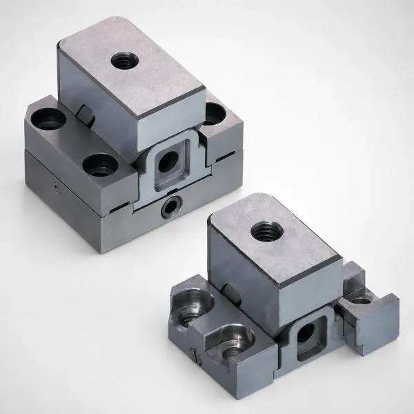
More gates bring their own cost. Each gate leaves a vestige, and thin-wall parts rarely allow visible gate marks on cosmetic surfaces. The mold shop should show the buyer the weld line map and the gate mark locations at DFM, before the runner layout is fixed.
Gate Types for Thin-Wall Parts
Film and fan gates suit wide flat thin-wall parts because they spread the melt across the edge. A film gate on a 0.6 mm wall part runs 0.4-0.6 mm deep (typical) and fills the width evenly. Submarine gates allow automatic degating, which matters on high-cavity tools.
The gate shear rate runs high on thin walls, typically above 100,000 s-1 (industry figures). The gate land needs hard steel to survive the wear. A balanced runner is the last piece, because in a multi-cavity thin-wall tool each cavity must fill at the same time and the same pressure.
| Gate Count | Effective Flow Length | Shrinkage Pattern | Warpage Risk |
|---|---|---|---|
| 1 gate | Full part length, 150-200:1 L/t typical | Strongly directional, one dominant shrink axis | Highest on long flat parts |
| 2 gates | Roughly half, 75-120:1 L/t | Two shrink zones meeting at the weld line | Moderate, weld line placement matters |
| 4 gates | Quarter, 40-60:1 L/t | Balanced, near-isotropic shrinkage | Lowest, more vestige marks |
← swipe to scroll →
Table 3. Gate count versus effective flow length and shrinkage direction on a 0.5 mm wall part. L/t ratios are typical for unfilled polypropylene.
Snap Check · True or False?
Gate position controls shrinkage direction, so it directly shapes which way a thin-wall part bows.
True False
Answer: True. Shrinkage aligns with the flow direction, and the gate decides where flow comes from — that is why gate placement is a listed mold-side warpage control.
Choose Mold Steel and Inserts for Heat Removal
Steel choice is a heat balance decision before it is a wear decision. Tool steel removes heat slowly, and thin cores made of tool steel run hot by default. The mold designer moves heat where the part needs it, and hardness where the part wears it.
Thermal Conductivity vs Hardness
H13 conducts about 29 W/m·K (typical) and hardens to HRC 48-52. DieStrike heat treats thin-wall cavities to HRC 62 for wear resistance on high-volume tools. Stainless grades like S136 drop to about 24 W/m·K (typical) but resist corrosion in medical and food-contact molds. P20 sits near H13 at about 29 W/m·K but only to HRC 28-32, which suits prototypes and low-volume work.
The trade is simple. Every material choice trades heat removal against wear and corrosion. The mold drawing should state the material, the hardness, and the conductivity target for every insert. A replacement insert made from a different grade changes the mold heat balance and can reintroduce the warpage the original design removed.
| Material | Thermal Conductivity | Hardness | Best Use in Thin-Wall Molds | Cost Factor |
|---|---|---|---|---|
| H13 | About 29 W/m·K | HRC 48-52 | Cavity and core plates, gate areas | Baseline |
| S136 (420 SS) | About 24 W/m·K | HRC 48-56 | Corrosive resins, medical molds | 1.3-1.6x |
| P20 | About 29 W/m·K | HRC 28-32 | Prototypes, low volume | 0.7-0.9x |
| Beryllium copper (C17200) | 105-130 W/m·K | HRC 36-42 | Slim cores under 4 mm, hot spots, pinch-offs | 2-4x |
← swipe to scroll →
Table 4. Mold material thermal conductivity and hardness for thin-wall tooling. Values are typical industry figures, and cost factors are relative to H13.
Where Beryllium Copper Pays
Beryllium copper conducts 105-130 W/m·K (typical), three to four times H13. It pays where a channel cannot reach. A 2.5 mm core pin, a deep pinch-off, or the steel under the gate all run hot. A BeCu insert pulls that heat to a nearby channel.
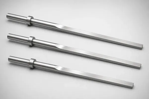
The trade is lower hardness, HRC 36-42, so BeCu sits behind the wear surface or in replaceable inserts. DieStrike builds custom mold inserts in BeCu and tool steel, and the insert spec includes the conductivity target. Rule of thumb: any core under 4 mm diameter on a thin-wall part gets a BeCu pin or a spray-cooled steel pin. The material change alone often closes half the cavity-core temperature gap.
Insert Rules for Thin Cores
Inserts are removable by design. Every insert gets a drawing with material, hardness, conductivity, and a replacement note, because the mold will outlive the first insert set. The pocket fit holds to the same precision as the cavity, and at DieStrike insert geometry holds to ±0.002 mm. A sloppy pocket changes heat transfer at the joint and shifts the temperature balance.
Set Mold Temperature for Thin-Wall Geometry
Mold temperature sets the freeze rate, and the freeze rate sets molded-in stress. Thin walls freeze in seconds, so the mold temperature window is narrow. Too cold, and the skin freezes with orientation locked in. Too hot, and the cycle stretches past the cost model. The mold design must deliver the temperature the material needs, not the temperature that is convenient to plumb.
Water Circuits at 40-80°C
Most thin-wall thermoplastics run mold temperatures of 40-80°C (typical), and water circuits deliver that range directly. POM runs 60-100°C, PBT 60-100°C, and nylon grades 60-90°C (typical). Standard water units hold ±2°C, and the circuit layout keeps the surface spread within 5°C across the mold. For parts that need 40-80°C, water is cheaper, cleaner, and easier to leak-test than oil.
Oil Circuits at 120°C and Above
Some resins need more. PC and PC/ABS blends call for mold temperatures of 80-120°C (typical), and thin-wall medical parts in PC often run the top of that range. Oil circuits deliver 120-200°C (typical industry range) and hold temperature on thin cores that water cannot reach.
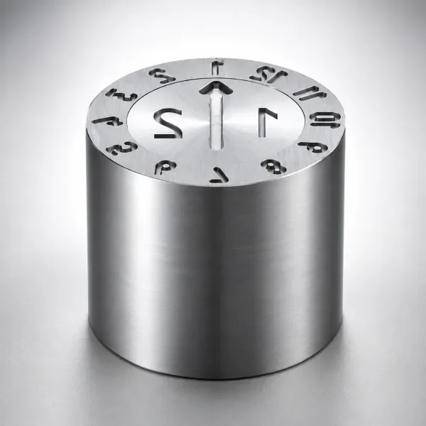
The mold side then needs o-ring sealed circuits, high-temperature seals, and an insulation plate between the mold and the platen. High mold temperature costs cycle time. A 0.6 mm PC part at 120°C mold temperature needs longer cooling before ejection than the same part at 80°C. The buyer should let the mold maker trade warpage against cycle at the DFM stage, when the cooling layout is still a drawing.
DieStrike's mold heating and cooling systems cover water, oil, and electric options. The DFM review states which one the part needs, with the mold temperature range on the drawing. Electric cartridge heaters serve localized hot spots, such as a thick boss, without re-plumbing the whole circuit.
Insulate the Mold From the Platen
Platens are heat sinks. An uninsulated mold bleeds 10-20°C at the mounting face (typical), which tilts the temperature profile across the cavity. An insulation plate 8-10 mm thick between mold and platen stabilizes the cavity temperature and cuts the energy bill at the same time (typical). The drawing should call out the insulation plate and its thickness, because retrofitting one after T1 changes the heat balance again.
Predict Warpage at DFM With Shrinkage Analysis
The last control happens before steel is cut. DFM review with shrinkage analysis turns warpage from a production surprise into a drawing decision. The tools are mold flow simulation, shrinkage compensation on the cavity dimensions, and a verification plan that ends at T1.
Run Shrinkage Analysis Before Steel Is Cut
Mold flow analysis predicts fill, packing, cooling, and the warp result in one pass. On a 0.6 mm wall part, the simulation shows the cavity to core temperature split, the shrinkage pattern, and the predicted flatness deviation. The useful output is relative, not absolute.
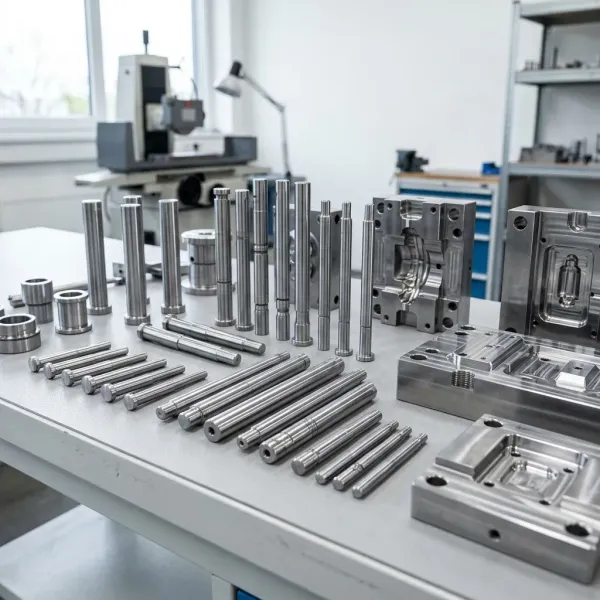
A simulation that says 0.08 mm warp versus a measured 0.12 mm still tells the designer which side of the part to fix. Simulation with good material data lands within 0.05-0.10 mm of measured thin-wall warp (typical). The material data sheet must match the production lot, because shrinkage behavior shifts between grades and batches.
Compensate the Cavity Dimensions
Shrinkage compensation is applied at the cavity, not at the mold base. For a 0.6 mm POM wall, the cavity is sized up by the material's shrink factor, roughly 1.8-2.2% (typical). Core pins are offset the same way. Compensation changes across the part because shrinkage changes with flow length and wall thickness.
The cavity drawing carries the shrink factor per feature, and the machinist verifies dimensions to the mold accuracy of ±0.005 mm. On high-tolerance thin-wall work, mold part geometry holds to ±0.002 mm at DieStrike. A compensated cavity that is machined wrong is worse than no compensation at all, so the check happens at the machine, not at T1.
Verify at T1
T1 sampling is the verification gate. The part is measured for flatness at the same points the simulation predicted, and cavity and core temperatures are logged with thermocouples. If warp exceeds the 0.10 mm spec, the measurement points out the hot side, and the fix is a local one.
DieStrike's DFM review returns within 24 hours, and the T1 trial service closes the loop with the steel in hand. Thin-wall molds are debugged in days, not weeks, when the drawing carries the numbers from this article.
FAQ: Thin-Wall Mold Warpage
Q1. What wall thickness counts as thin-wall, and when does warpage get serious?
Thin-wall means under 1.0 mm, with typical production parts at 0.4-0.8 mm. Warpage gets serious when flatness must hold under 0.10 mm on a part with an L/t ratio above 150:1. Cooling balance and gate placement decide the outcome there.
Q2. What cavity to core temperature difference causes warpage?
The target is under 5°C at steady state (typical practice). A 10-15°C differential across a 0.6 mm wall produces measurable bow, and the fix is mold-side, either a balanced circuit, a BeCu insert, or both. Measure the split with thermocouples at T1.
Q3. Does beryllium copper fix warpage by itself?
No. BeCu removes heat 3-4x faster than H13 at 105-130 W/m·K, which fixes the hot side of the temperature split. Gate position and wall uniformity still control shrinkage direction. Use BeCu for cores under 4 mm and hot spots, and keep the hardness trade in mind, HRC 36-42.
Q4. Can mold flow simulation predict thin-wall warpage before the mold is built?
Yes, for ranking and direction. With good material data, shrinkage analysis lands within 0.05-0.10 mm of measured warp on thin-wall parts (typical). The value is that it points the designer at the right fix before steel is cut, when a change costs hours instead of days.
The Bottom Line
A thin-wall mold warps parts when the cavity and core cool unevenly, the wall steps without a transition, or the gate fights the shrinkage direction. Every one of those is a drawing decision. DieStrike builds thin-wall molds under IATF 16949 with 120+ machines and holds mold accuracy to ±0.005 mm. Send your part file through the contact page for a warpage and cooling review.
KEEP READING
Related Reading
5 Mold Cooling Channel Design Tips for Faster Cycles
Mold maker's 5 cooling channel design rules: channel-to-cavity distance 2-2.
Read articleArticle5 Shrinkage Compensation Rules for Mold Design
Shrinkage compensation decides mold accuracy. Five rules: material rates from 0.3% to 2.
Read articleArticle5 Ways to Reduce Mold Cost Without Cutting Quality
Five proven ways to reduce injection mold cost without cutting quality: DFM before quoting, right-sized cavity count,…
Read articleArticle7 Gate Design Best Practices for Balanced Filling
Mold maker's 7 gate design rules for balanced multi-cavity filling: gate depth 50-80% of wall thickness, land 0.5-1.
Read articleNEXT STEP
Ready to Start Your Mold?
Send us your element dimensions or part numbers — our team responds within 24 hours with pricing and lead time.

Written by
Ray ChanMold Buyer's Guide Author · Precision Mold Manufacturing Specialist. Ray helps global importers, distributors and OEMs source factory-direct molds and mold parts.