
How to Troubleshoot Mold Defects: 9 Common Causes
Table of Contents
Your mold ran 40,000 shots without a problem. Then flash appeared on cavity 3, a 0.08 mm feather along the parting line. QC rejected 12,000 parts in one batch. The line stopped for 11 hours while toolroom and process engineers argued about clamp tonnage. The part was fine. The mold was worn. That sequence plays out weekly in shops that treat mold defects as a process problem. Most defects are decided in the tool before the first shot: parting line seal, vent depth, gate geometry, cooling channel layout, draft, and ejector system. This guide ranks the tooling root causes of the 9 most common injection mold defects, gives the measurement that confirms each one, and puts numbers on the fix.

The Snapshot
- Flash is a seal problem. Vent depth must stay at 0.02-0.05 mm, and the parting line must hold that gap closed against full cavity pressure.
- Short shots point to gate and vent first. A flow length to wall thickness ratio above 150 for most resins means the gate or runner is undersized.
- Sink marks follow cooling and wall ratio rules. Cooling line pitch should be 2-2.5× the channel diameter. Ribs should be 0.5-0.6× the wall thickness.
- Warpage follows differential shrinkage. A surface temperature spread above 10-15 °C across the part is a cooling imbalance, not a material problem.
- Ejector pin marks are pressure marks. Keep pin-tip bearing pressure below 25-35 MPa for PP and 60-75 MPa for PC. Pins must sit flush within ±0.02-0.05 mm.
- Draft of 0.5-1° per side is the floor on polished steel. Most stuck-part and ejector-mark fights are decided in DFM, before steel is cut.
Why Tooling Comes First
Every defect leaves a fingerprint. A flash that follows one cavity is a parting line fault. A short shot at the same corner on every shot is a gate or vent fault. A mark that grows after 50,000 shots is wear. Process settings can mask these for a shift, but the cause stays in the steel.
The fastest triage is a 50-shot run at a fixed, documented process. If the defect moves or appears on a different cavity, think process. If it stays at the same location, the tool owns it. Then inspect the tooling suspects in likelihood order: parting line seal, vents, gate, cooling, ejector system, and draft.
DieStrike builds IATF 16949-certified molds with ±0.005 mm standard machining accuracy and ±0.002 mm on critical geometry. Cavities are heat treated to HRC 62. Our 24-hour DFM review checks venting, gating, cooling, and ejector layout before steel is cut, which is where most of these defects die cheaply.
Snap Check · True or False?
Flash is a process problem first — raise clamp tonnage before touching the mold.
True False
Answer: False. Flash is a seal problem. Vent depth must hold at 0.02-0.05 mm and the parting line must keep that gap closed against full cavity pressure — both are tooling checks, which is why this guide starts with tooling.
Flash: Parting Line Wear and Clamp Seal
Symptoms
Flash is a thin fin of resin at the parting line, typically 0.02-0.2 mm thick. It can ring one cavity or the whole parting line. Glossy edges and a constant location are the usual signs. Flash that appears suddenly after a long run points to wear, not setup.
Root Causes in Likelihood Order
- Parting line wear or mismatch. The steel crushes or erodes at the seal edge. With glass-filled resins, expect 0.02-0.1 mm of parting line wear over 100,000 shots.
- Vent depth cut too deep. A vent cut to 0.08 mm for a resin that needs 0.03 mm is a flash channel.
- Insert shut-off mismatch. Core and cavity inserts proud or low by more than 0.005 mm open a gap at the seal.
- Clamp force below requirement. The rule of thumb is 3-5 tons per square inch of projected area, a typical industry figure. Cavity pressure then lifts the parting line.
Diagnosis
Measure flash thickness with a feeler gauge or microscope. Blue the parting line and close the mold on a blank to see where the seal actually touches. Confirm clamp tonnage against projected area.
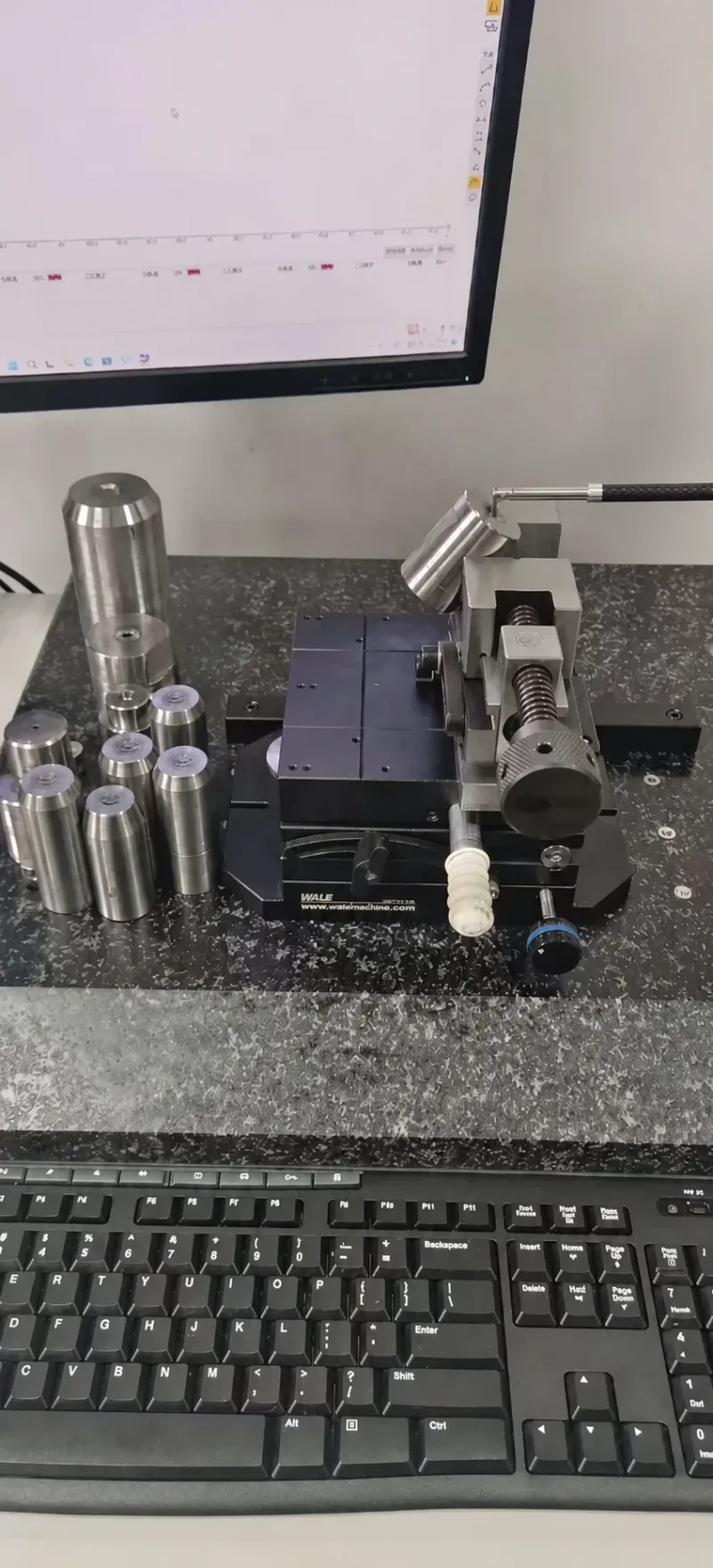
Check vent depth with a blade gauge. The working band is 0.02-0.05 mm. Anything deeper becomes a flash path on low-viscosity resins.
The Fix
Re-cut or laser weld the worn parting line and re-machine it to flatness within 0.005 mm. Harden the seal edge to HRC 62. Bring vents back to 0.02-0.05 mm depth with a 1-2 mm land and a 0.3-0.5 mm deep relief groove. Verify with a 50-shot run: zero flash at shot 50 is the pass condition.
DFM Prevention
Specify parting line steel above HRC 48 at design, typical for production molds. Avoid knife-edge shut-offs. Confirm projected area and required clamp force in the DFM before quoting the mold.
Short Shot: Gate Capacity and Trapped Air
Symptoms
The part is incomplete at the end of flow. Corners and thin edges are missing or rounded. A short shot at the same location on every shot is a flow path fault. Intermittent short shots with burn marks point to trapped air and blocked vents.
Root Causes in Likelihood Order
- Gate or runner undersized. The pressure drop kills the fill before it completes. Gate depth should be 50-80% of the wall thickness, with width 2-3× the depth, typical edge gate practice.
- Blocked or missing venting at last-to-fill. Trapped air compresses and blocks the melt front. Look for charred spots at the short area.
- Runner imbalance in multi-cavity. One cavity starves while neighbors fill.
- Gate freeze-off before packing. A gate that is too small, or too long in the land, freezes early.
Diagnosis
Weigh the part against a known full shot. A short shot typically runs 3-15% under weight. Measure the gate cross-section with a pin gauge and compare it to the wall. Check the end-of-fill zone for vents and burn marks. If the flow length to wall thickness ratio is above 150, the flow path is long for the wall.
The Fix
Enlarge the gate in 0.1-0.2 mm steps. Keep the gate land at 1-1.5 mm. Add or open end-of-fill vents to 0.02-0.05 mm depth. Rebalance runners in 0.5-1 mm diameter steps. Verify with 30 shots: full parts, weight within 0.5% of target.
DFM Prevention
Run a flow length analysis in DFM and keep the L/t ratio below 150. Place vents at the last-to-fill location. Size the gate in the review, not on the floor.
Sink Marks: Cooling Balance and Wall Ratios
Symptoms
A shallow depression on a flat surface, usually opposite a rib or boss. Sink marks appear during cooling and are easiest to see under raking light. They grow on thick sections and where the back side is uncooled.
Root Causes in Likelihood Order
- Cooling channels too far from the cavity or wrongly pitched. The local zone stays hot and shrinks last. Pitch should be 2-2.5× the channel diameter, with distance to the wall at 1.5-2×.
- Rib and boss mass too large. A rib thicker than 0.6× the wall creates a local hot mass that sinks.
- Uneven cooling across the cavity. One zone runs 10-15 °C hotter than the rest.
- Gate freeze-off before packing completes. The thick zone cannot be fed during hold.
Diagnosis
Map the surface temperature with an infrared thermometer. A spread above 10-15 °C across one part is an imbalance. Measure the rib-to-wall ratio from the drawing or a section. Check each cooling circuit for flow: 8-12 L/min per circuit is a typical target, with a 3-5 °C inlet to outlet delta.

Confirm the channel-to-wall distance against the drawing. A channel sitting 4× the diameter from the surface does almost nothing for the zone above it.
The Fix
Add or reposition cooling lines to a 2-2.5× diameter pitch. Use bubblers or baffles inside deep ribs. Machine rib thickness down to 0.5-0.6× the wall. Verify with a straightedge or profilometer: sink depth must stay under the drawing limit, typically 0.05-0.1 mm.
DFM Prevention
Apply the 0.5-0.6× rib ratio in DFM. Review the cooling layout with pitch and wall distance calculated. Put a gate over or near the thick section so hold pressure can feed it. The full wall-thickness rules live in our guide on how to design for moldability.
Weld Lines: Gate Placement and Venting
Symptoms
A visible line where two flow fronts meet, often around a core or hole. The line is a weak point and can crack under load. A weld line in the same position on every shot is a flow path signature, not a process accident.
Root Causes in Likelihood Order
- Gate placement. Two fronts travel different paths and meet late, cool, and knit poorly.
- No vent at the weld zone. The fronts meet over trapped air and fold gas into the knit.
- Gate too small. The fronts cool before they meet.
- Cooling imbalance at the meeting zone. The local mold surface runs cold.
Diagnosis
Mark the weld line position on the part and compare it to the flow simulation. Check for a vent at that exact spot. Break or tensile test the weld zone: unreinforced resins typically reach 50-80% of bulk strength at a good weld, and glass-filled grades drop lower. Those are industry figures, and the material data sheet confirms the grade's weld factor.
The Fix
Move or add a gate so the fronts meet head-on with less travel. Add a vent at the weld line at 0.02-0.05 mm depth. Enlarge the gate to keep the fronts hot. Balance cooling to lift the zone temperature, typically 40-80 °C for most engineering resins. Verify with a tensile test against the baseline.
DFM Prevention
Run mold flow in DFM and mark every weld line on the part drawing. Place vents at each marked zone. Use the material supplier's weld-line strength data to decide if a weld zone can sit in a loaded area.
Warpage: Cooling Channel Balance
Symptoms
The part twists, bows, or cups after ejection. Flatness and parallelism drift out of spec. Warpage can grow after ejection as the part continues to cool and shrink.
Root Causes in Likelihood Order
- Cooling channel imbalance. One side cools faster and shrinks more. Pitch and wall distance must match on both halves.
- Non-uniform wall thickness. Thick sections shrink later and pull the part.
- Asymmetric ejector layout. The part is pushed out unevenly and distorts.
- Gate location driving orientation shrinkage. Fiber-filled resins shrink differently along and across flow.
Diagnosis
Measure flatness at ejection and again after 24 hours. Post-mold shrinkage runs 0.1-0.5% for semicrystalline resins, typical industry figures. Map the surface temperature across the part. A spread above 10-15 °C points to the cooling circuits. Check flow in each half with a flow meter.
The Fix
Rebalance the circuits to equal pitch at 2-2.5× diameter on both halves. Add channels to the hot side. Run independent mold temperature control zones per half, typically 10-80 °C. Verify flatness against the drawing, commonly 0.1-0.3 mm over 100 mm.
DFM Prevention
Design for uniform walls in DFM. Review the cooling layout for symmetry. Place gates for balanced shrinkage and run a warp simulation on fiber-filled grades.
Ejector Pin Marks: Pressure and Pin Layout
Symptoms
White crescents at each pin location, visible under raking light. A raised ring or a dimple at the pin tip. Marks that grow over a run signal wear or blocked vents, not design.
Root Causes in Likelihood Order
- Pin-tip bearing pressure above the material limit. Keep it under 25-35 MPa for PP, 40-55 MPa for ABS, and 60-75 MPa for PC, typical figures.
- Pin layout with too little total area. Total tip area should reach 0.3-1% of projected area on shallow parts, and more on deep ribs.
- Pin flush out of tolerance. Pins must sit flush within ±0.02-0.05 mm. Proud pins leave rings, low pins leave dimples.
- Ejector system binding. Misaligned guide pins and worn return springs add force at the tip.
Diagnosis
Check pin flush with a dial indicator on the closed mold. Measure tip diameter and count the pins. Calculate bearing pressure as ejection force divided by total tip area. Compare the number to the material limit above.
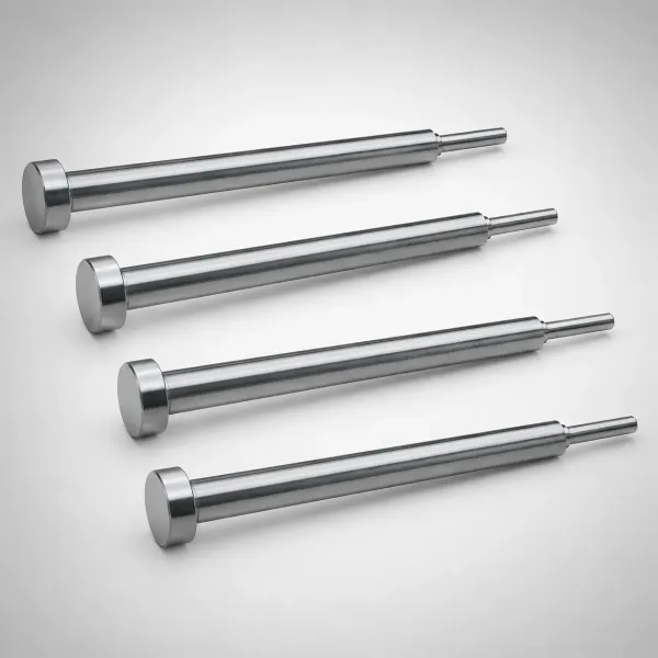
Run a 50-shot sequence and photograph the surface at shots 10, 20, 30, 40, and 50 under 30° raking light. A mark that appears at shot 40 but not at shot 10 is a wear problem. Full detail lives in our guide on how to prevent ejector pin marks.
The Fix
Add pins or larger pins until bearing pressure drops below the material limit. Grind pins flush within ±0.02-0.05 mm. Break pin edges to a 0.05-0.1 mm radius. Polish cores to Ra 0.2-0.4 µm and add 0.5-1° draft to cut ejection force by up to 50%. Verify 50 shots with zero whitening at every pin.
DFM Prevention
Calculate pin layout and bearing pressure in DFM. Specify draft and core polish on the drawing. Standard ejector pins from Ø1 mm upward ship in 3-7 days, so a layout change is fast once the review flags it.
Gate Vestige: Gate Size and Land
Symptoms
A gate stub left on the part, 0.1-0.5 mm tall, with a rough break surface. It can sit on a cosmetic face or an assembly datum. Stub height that varies shot to shot points to gate wear.
Root Causes in Likelihood Order
- Gate land too long. Land of 1-1.5 mm is typical. Longer land leaves a taller stub and adds pressure drop.
- Gate cross-section too large. A bigger break area leaves a bigger scar.
- No designed break point. A sub-gate with the standard 15-30° included angle snaps clean. A square edge tears.
- Gate edge erosion. A rounded edge moves the break point and grows the stub.
Diagnosis
Measure stub height with a height gauge. Most drawings hold vestige to 0.1-0.3 mm. Inspect the gate edge at 10× magnification for rounding and erosion. Compare the land length to the drawing.
The Fix
Shorten the land to 1-1.5 mm. Add or re-cut the break notch angle. Polish the gate bore to cut friction. If the spec is 0.1 mm or tighter, move to a sub-gate or a hot runner tip. Verify 30 shots with stub height inside spec.
DFM Prevention
Pick the gate type by the cosmetic requirement in DFM. Agree the vestige tolerance before steel is cut. Size the land and break geometry in the review.
Flow Marks: Gate Location and Cavity Surface
Symptoms
Wavy bands or rings near the gate, sometimes a jelly-roll pattern. Flow marks sit close to the gate when the melt jets across the cavity. They are most visible on glossy surfaces.
Root Causes in Likelihood Order
- Gate location and angle. The melt shoots straight across the cavity instead of flowing along the wall.
- Gate too small or land too long. The melt accelerates and jets.
- Cavity surface too cold at the gate zone. The skin freezes in ripples. Typical mold temperatures run 40-80 °C.
- Cold slug entering the cavity. A missing or short cold slug well lets the cold front in.
Diagnosis
Confirm the marks are near the gate, which points to jetting, not across the whole part. Check gate size against the wall thickness. Measure mold surface temperature with an infrared gun. Check the cold slug well length, which should be 1-1.5× the runner diameter.
The Fix
Re-angle or move the gate so the melt hits a wall first. Enlarge the gate by 0.1-0.2 mm and shorten the land to 1-1.5 mm. Polish the gate and cavity to Ra 0.2-0.4 µm. Extend the cold slug well. Verify 30 shots with no marks under raking light.
DFM Prevention
Review gate position against the cavity geometry in DFM. Specify the surface finish at the gate zone. Put the cold slug well in the runner layout from the start.
Stuck Parts: Draft and Ejection Layout
Symptoms
The part stays on the core or fails to eject. The operator clears the cavity by hand on every cycle. Ejector pins push through the part or bend. Ejection force climbs over a run.
Root Causes in Likelihood Order
- Draft too low. 0.5-1° per side is the floor on polished steel. Deep cores over 25 mm need 1-2°, and textured surfaces need 2-3°.
- Undeclared undercuts. The part locks onto the steel and has no release path.
- Ejector layout too small or off-center. The part tilts and jams.
- Over-packing on the core with a rough surface. Friction sticks the part. Core polish should be Ra 0.2-0.4 µm.
Diagnosis
Listen to the ejection stroke. A loud pop is high friction. Check the draft angle against the drawing with a protractor or a 3D scan. Verify the ejector stroke clears the part height plus 5-10 mm. Check that the pin pattern is balanced around the part centroid.

Inspect the guide pins and return springs. Binding in the ejector plate adds force at every pin tip. Springs are consumables with a typical life of 1 million cycles and should be replaced at scheduled maintenance.
The Fix
Add 0.5-1° of draft by machining or EDM. Polish the core to Ra 0.2-0.4 µm. Add ejector pins or larger pins to spread the load. Replace worn springs and re-align the ejector plate. Verify 50 free ejections with steady force and no push-through.
DFM Prevention
Specify draft on every vertical wall in DFM. Review undercuts for lifters and slides. Lay out ejector pins around the centroid and estimate ejection force before quoting.
Systematic Troubleshooting: A Tooling-First Sequence
When a defect survives process changes, run this sequence. It costs one afternoon and settles the argument with data. First, classify the defect and mark its location on a part drawing. Second, run 30-50 shots at a fixed, recorded process. Third, decide ownership: a defect that stays at one location is tooling, one that moves is process. Fourth, inspect the tooling suspects in this order: parting line seal, vents, gate, cooling, ejector system, draft. Fifth, change one thing at a time and verify with 30-50 shots. Sixth, photograph and log every change in the mold maintenance file.
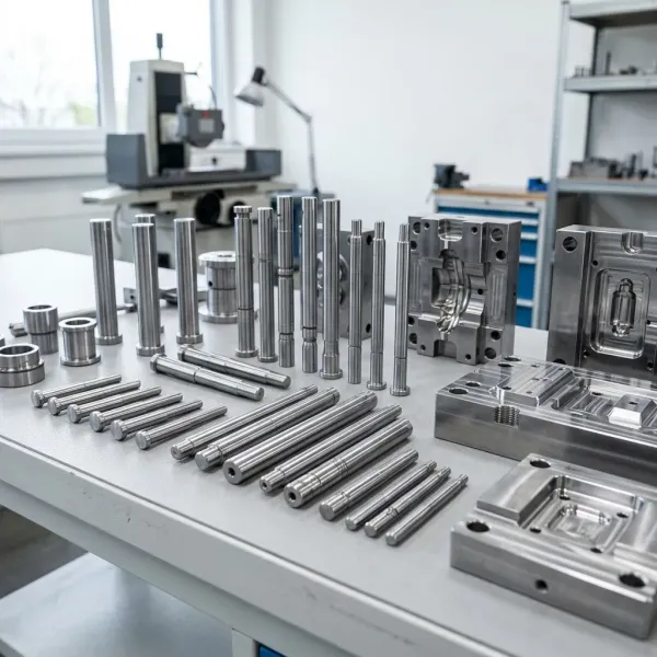
The table below maps each defect to its two most likely tooling causes, the quick check, and the fix. Use it as the first page of your troubleshooting log.
| Defect | #1 Tooling Cause | #2 Tooling Cause | Quick Check | Fix |
|---|---|---|---|---|
| Flash | Parting line wear or mismatch | Vent depth cut too deep | Blade-gauge vents at 0.02-0.05 mm, blue the parting line | Re-cut or weld parting line, harden to HRC 62, reset vent depth |
| Short shot | Gate or runner undersized | Blocked end-of-fill vents | Weigh part, measure gate vs wall, check L/t ratio | Enlarge gate 0.1-0.2 mm, open vents to 0.02-0.05 mm |
| Sink marks | Cooling lines too far or sparse | Rib mass over 0.6× wall | IR surface map, check pitch vs diameter | Cool at 2-2.5× diameter pitch, cut ribs to 0.5-0.6× wall |
| Weld lines | Gate placement splits the flow | No vent at the weld zone | Compare flow sim to part, check weld spot | Move gate, vent weld zone at 0.02-0.05 mm |
| Warpage | Cooling imbalance between halves | Non-uniform wall thickness | Surface temp spread, 24 h flatness check | Balance pitch 2-2.5× on both halves, uniform walls |
| Ejector pin marks | Pin bearing pressure too high | Pin flush out of ±0.02-0.05 mm | Calculate pressure vs material limit | Add pin area, grind flush, add draft 0.5-1° |
| Gate vestige | Gate land too long | Gate too large or worn edge | Measure stub height, inspect edge at 10× | Land at 1-1.5 mm, break notch, polish bore |
| Flow marks | Gate location causes jetting | Cold gate-zone surface | Marks near gate, check mold temperature | Re-angle gate, enlarge 0.1-0.2 mm, polish Ra 0.2-0.4 µm |
| Stuck part | Draft below 0.5-1° | Undercut or ejector layout fault | Check draft angle, listen to the ejection stroke | Add draft, polish core Ra 0.2-0.4 µm, rebalance pins |
← swipe to scroll →
Table: typical industry figures; verify against your program.
Verify every fix the same way: run 50 shots and inspect at shots 10, 20, 30, 40, and 50. A defect that appears only late in the run is wear. A defect present at shot 10 is a design or machining fault. Write the pass condition into the maintenance file before the work starts, and do not argue about it on the floor.
Snap Check · True or False?
A flow-length-to-wall-thickness ratio above 150 for most resins points to an undersized gate or runner.
True False
Answer: True. That ratio is the shortcut the short-shot section uses: long flow path plus thin wall means the gate or runner is the first suspect, not the machine.
Frequently Asked Questions
Q1. What is the most common tooling cause of flash?
Parting line wear or mismatch. The seal edge erodes and a gap opens, typically 0.02-0.1 mm over 100,000 shots. Check clamp force against the 3-5 tons per square inch rule, then blue the parting line and confirm vent depth stays at 0.02-0.05 mm.
Q2. How do I fix short shots without touching the machine?
Work the flow path. Enlarge the gate in 0.1-0.2 mm steps and keep the land at 1-1.5 mm. Open end-of-fill vents to 0.02-0.05 mm. Keep the flow length to wall thickness ratio under 150. Verify with 30 shots and a weight check within 0.5% of target.
Q3. What vent depth should an injection mold use?
0.02-0.05 mm at the parting line and inserts, with a 1-2 mm land and a 0.3-0.5 mm deep relief groove. Low-viscosity resins like PP and PE sit at the shallow end. High-viscosity grades like PC sit at the deep end.
Q4. How much draft angle prevents stuck parts and ejector marks?
0.5-1° per side on polished steel is the floor. Use 1-2° on cores deeper than 25 mm and 2-3° on textured surfaces. Pair draft with core polish at Ra 0.2-0.4 µm and adequate ejector area.
Q5. How do I know if a defect is tooling or process?
Run 50 shots at a fixed, documented process. A defect pinned to one cavity or one location is tooling. A defect that moves or appears across all cavities is process. Inspect at shots 10, 20, 30, 40, and 50. A mark that shows up late in the run is wear.
The Final Call
Flash, short shots, and warpage are tooling problems with known numbers. Check the tool first, one change at a time. DieStrike builds IATF 16949-certified molds to ±0.005 mm with HRC 62 cavities and a 24-hour DFM review.
Send us your part drawing and defect photos for a tooling verdict.
KEEP READING
Related Reading
5 Mold Cooling Channel Design Tips for Faster Cycles
Mold maker's 5 cooling channel design rules: channel-to-cavity distance 2-2.
Read articleArticle5 Shrinkage Compensation Rules for Mold Design
Shrinkage compensation decides mold accuracy. Five rules: material rates from 0.3% to 2.
Read articleArticle5 Ways to Reduce Mold Cost Without Cutting Quality
Five proven ways to reduce injection mold cost without cutting quality: DFM before quoting, right-sized cavity count,…
Read articleArticle7 Gate Design Best Practices for Balanced Filling
Mold maker's 7 gate design rules for balanced multi-cavity filling: gate depth 50-80% of wall thickness, land 0.5-1.
Read articleNEXT STEP
Ready to Start Your Mold?
Send us your element dimensions or part numbers — our team responds within 24 hours with pricing and lead time.

Written by
Ray ChanMold Buyer's Guide Author · Precision Mold Manufacturing Specialist. Ray helps global importers, distributors and OEMs source factory-direct molds and mold parts.