
How to Design Thermoset Injection Molds: BMC and Phenolic
Table of Contents
A phenolic tool built to thermoplastic habits comes back from the first trial with a 0.4 mm flash fin around every parting line and three cavities short at the last-fill corner. Deflash labour on a phenolic part runs 0.2 to 0.5 mm of hand work per edge, and a vent blocked by cured resin repeats the same void in the same place until the tool strips for a 100 to 500 shot cleanout.
This guide covers thermoset injection tooling alone, and the numbers behind the hot cavity, the reactive-melt feed system, cure-gas venting, draft and release, and the steel that survives an abrasive charge, while compression, transfer and the material choice itself stay with the thermoset versus thermoplastic and linked guides.
The Snapshot
- The mold runs hot, not cold. A thermoset injection cavity sits at 150 to 200 °C with ±5 °C control. The same base for a thermoplastic would be chilled to 60 to 90 °C and would never cure the part.
- Cure time is the cycle. A 2 to 6 mm section cures in 30 to 120 seconds at 175 °C against 5 to 20 seconds for a comparable thermoplastic wall, and wall thickness drives the clock.
- Vents at 0.02 to 0.04 mm every 15 to 25 mm. The gas is a cure reaction product, not trapped air, so a plugged vent shows as a void or a short at the same location on every shot.
- Cavity steel at HRC 54 to 56. A charge carrying 15 to 30 percent glass wears a soft cavity through in 20,000 to 50,000 shots, then the flash grows with the gap.
- Every runner is scrap. Feed the melt through a 6 to 10 mm full-round runner, or a hot-runner block held at 85 to 95 °C that keeps the charge reactive between shots.
Why Thermoset Injection Tooling Differs
A thermoplastic mold removes heat. The melt arrives at 230 to 300 °C, the steel sits at 60 to 90 °C, and the part freezes in 5 to 20 seconds because a thin wall and a conductive steel pull heat out fast. Every cooling decision in that tool points in one direction.
A thermoset injection mold runs the other way. The cavity sits at 150 to 200 °C, the charge enters at 60 to 100 °C at the nozzle, and the metal has to deliver heat into the cavity and hold it there. There is no frozen skin and no cooling credit that a longer cycle can buy back.
Crosslinking, not solidification, sets the cycle. A thermoset melt thins as it warms, flows as a low-viscosity liquid, then gels and stops as the cure runs through the section. A 2 to 6 mm wall cures in 30 to 120 seconds, and a 3 mm phenolic wall takes 30 to 60 seconds at 175 °C. Cure time tracks wall thickness and cavity temperature, so a heavy rib or a thick boss adds seconds that no process setting removes.

Pressure is lower in a reactive melt, but shear and residence time carry the risk. A glass-filled charge shows a shear-thinning viscosity from roughly 1,000 to 10,000 Pa.s at the low shear of a runner up to 10,000 to 100,000 Pa.s as it passes a gate. The charge can gel in the feed system if it stays warm for too long, and once a runner cures the tool strips to bare plates.
Process Window: Viscosity, Gel and Cure Time
Thermoset injection covers three material families, and each one moves the tool numbers before the drawing starts.
- BMC, in bulk or sheet form. A resin, filler and fiber paste carrying 15 to 30 percent glass. It flows at low pressure, fills ribs and bosses, and releases from a polished cavity.
- Phenolic. A dense, hard, heat-resistant material at roughly 1,600 to 1,800 kg per m3. It cures fast, resists heat, bonds to steel, and needs a protective surface on the tool.
- Epoxy. Used for encapsulation of coils and sensors, often over a hardened insert and with a low-stress cure.
The screw is the first tool decision. Thermoset injection runs a low-compression screw, often 1.0 to 1.5 to 1, with a short feed and a shallow flight that warms the charge instead of shearing it. The barrel holds 60 to 100 °C so the material stays reactive at the nozzle.
Cure time is a function of wall and temperature, and it is not linear in either. A 3 mm wall at 175 °C runs 30 to 60 seconds, while the same wall at 150 °C needs 60 to 120 seconds. Set the cavity at the highest temperature the datasheet allows, then trim for dimensional stability rather than for cycle.
There is no gate freeze in a thermoset, and pressure behaves differently because of it. A thermoset gate cures while the machine still holds pressure, so pack pressure, cavity temperature and gate land length decide part density together.
Heating Circuits, Insulation and the Cavity Gradient
Heating is the core of the tool, and the layout has to be chosen before the cavity block is cut. Electric cartridge heaters or oil circuits hold the cavity at 150 to 200 °C within ±5 °C. Cartridge heaters are simple and responsive and suit small or medium blocks. Oil circuits give a uniform face on a large or multi-cavity tool and hold within ±2 to 3 °C when the flow stays turbulent.
| Zone | Typical temperature | Hardware | Failure if wrong |
|---|---|---|---|
| Barrel and nozzle | 60 to 100 °C | Temperature-controlled barrel, low-compression screw | Charge cures in the screw, then days of downtime |
| Cavity face | 150 to 200 °C | Cartridge heaters or oil circuits, ±5 °C control | Under-cure, a soft part, and dimensional drift |
| Hot-runner block | 85 to 95 °C | Insulated block with its own controller | Charge cures in the runner and the tool strips |
| Insulating platen face | Cold face under 80 °C | Glass-filled sheet, 10 to 20 mm thick | Heat bleeds into the press and the gradient grows |
| Ejector side | 100 to 150 °C | Insulated ejector plate, guided ejection | Cold ejector plate chills the part and it cracks |
← swipe to scroll →
Table note: temperature bands are typical industry values for thermoset injection. Confirm against the material datasheet and the setpoints recorded during the trial, and keep both in the tool file.
A 20 to 30 °C gradient across the cavity shifts cure by 10 to 20 percent, which shows as a dimensional spread from the center to the outer cavities. Insulate the platen face with a 10 to 20 mm sheet, keep thermocouples 10 to 15 mm below the cavity surface, and hold the face within ±5 °C before a capability study starts.
Sprue, Runners and Gating for a Reactive Melt
Gate design in a reactive melt balances shear against cure. A gate that is too small raises viscosity at the entry and can scorch a filled charge. A gate that is too large slows the cure at the gate and leaves a soft, stringy vestige that is hard to remove.
Edge and fan gates of 1.5 to 4 mm work for most BMC and phenolic parts, with a land length of 0.5 to 1.0 times the gate width so shear heating does not cook the charge at the entry. Pin and drop gates of 1.0 to 2.5 mm suit small parts, but a cured gate makes a clean degate harder than on a thermoplastic part, so plan the gate where the vestige is not cosmetic.

Feed the melt through a full-round runner of 6 to 10 mm, sized so a viscous charge at 1,000 to 10,000 Pa.s does not freeze in the sprue. Half-round and trapezoid runners, common in thermoplastic tools, raise the pressure drop and expose a hot thermoset runner to the wrong face. A cold-runner plate or an insulated hot-runner block held at 85 to 95 °C keeps the charge reactive between shots and turns a scrap runner into reusable compound, which matters when the runner runs 20 to 40 percent of the shot weight.
Balance the runner so all cavities fill in the same window, because a thermoset that gels while filling does not recover from an unbalanced set the way a thermoplastic does.
Venting Cure Gas: Depth, Spacing and Voids
A thermoset cracks volatile byproducts as it cures, and that gas has to leave the cavity. A trapped pocket of reaction gas burns, chars or leaves a void, and the defect sits in the same spot on every shot, so choose vent positions from the fill pattern.
Vent lands of 0.02 to 0.04 mm, spaced every 15 to 25 mm around the periphery and 3 to 6 mm from the last point to fill, let the gas out without letting a low-viscosity charge flash. Deeper than 0.04 mm and a thin BMC paste bleeds through and leaves a fin. Shallower than 0.02 mm and the land closes after a few hundred shots of cured dust.

Run the vent land 3 to 6 mm long, then open into a 0.5 to 1 mm relief channel to atmosphere so the gas is not throttled by a long gap. On a deep pocket or a last-fill corner, add a vent at the very end of the flow, because the fill pressure is too low to push gas out of a blind corner.
Clean the vents on a shot count. Cured resin and filler dust close a 0.03 mm land in 100 to 500 shots, and the first sign is a void or a short where the trial ran clean.
Draft, Parting Lines and Shut-Off Numbers
Draft pulls two ways in thermoset tooling. A well-filled BMC charge releases from a lightly drafted polish, but a phenolic part grips and can crack if the wall is thin. Set the draft from the material, not from habit.
BMC runs 0.5 to 1.0 degree of draft on a polished cavity. Phenolic needs 1 to 2 degrees plus a release surface, because the cured part bonds to bare steel. Apply the same rule to cores, ribs and bosses. A 10 mm boss with 0.5 degree of draft loses only 0.09 mm of diameter over its height, and that is enough to grip when the material bonds.
The parting line carries the flash risk. The charge stays fluid until it gels, so a 0.05 mm steel gap at the parting line prints a 0.05 mm flash that has to be removed by hand. On a phenolic part that 0.05 mm of flash costs 0.2 to 0.5 mm of deflash labour per edge, which is why the seal land belongs at the low end of the clearance range.
Specify shut-off clearances tight on the seal lands and put them in a hardened insert at HRC 54 to 56 so they keep their geometry over the tool life. Add a 3 to 5 degree taper on every vertical shut-off so the blocks close on a wedge rather than on two parallel walls.
Ejection and Release: BMC versus Phenolic
Release behaviour separates the two main charge families, and the ejector layout follows from it.
A BMC part at 15 to 30 percent glass releases cleanly from a polished cavity with 0.5 to 1.0 degree of draft, so a straightforward ejector pin pattern on the ribs and bosses demolds it with light force. Keep pins off cosmetic faces and off any wall under 2 mm, where a point load leaves a witness mark.
A phenolic part bonds to steel as it cures. Tooling for phenolic carries 1 to 2 degrees of draft, no undercuts that grip, and a release surface, typically hard chrome at 0.02 to 0.05 mm or a PTFE-based coating. Some shops run a mold-release cycle instead of a coating, but a release agent on a part that is later bonded or painted creates a different problem.
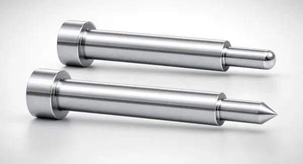
Eject at temperature. A thermoset part is still warm and slightly compliant when the tool opens, and it separates with lower force than a part that has cooled in the cavity. Time ejection to start within 1 to 3 seconds of opening, and use a stripper plate on thin, flat parts so the push spreads over the edge instead of concentrating on a pin.
Size the ejector system for the wall, not for the shot weight, because a sharp pin on a 2 mm phenolic wall prints a mark or cracks it.
Steel and Surface Treatment for Abrasive Charges
Steel choice in a thermoset injection tool is set by two loads: abrasion from filler and corrosion from cure byproducts. DieStrike builds and qualifies the mold, so the numbers below are tool requirements on the drawing set.
A glass-filled charge at 15 to 30 percent wears a soft cavity through its seal lands in 20,000 to 50,000 shots, and the flash grows as the gap opens. Cavity inserts belong at HRC 54 to 56. A shop that holds mold geometry to ±0.005 mm, with ±0.002 mm on EDM and jig-ground features, keeps a seal land at the design number after heat treatment, which is what stops the flash from creeping.
For phenolic and other corrosive grades, use a corrosion-resistant tool steel and add a surface layer. Nitriding on the cavity, or hard chrome at 0.02 to 0.05 mm on seal lands, gates and core pins, resists both the abrasive glass and the acidic cure residue, and chrome can be stripped and re-plated when it wears.
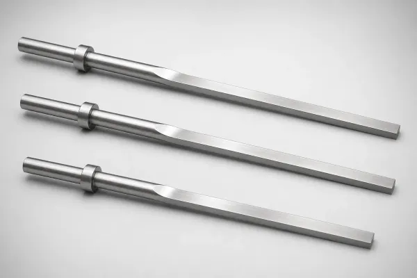
Do not leave a core pin soft. A filled charge abrades a low-hardness pin at the gate and along the flow path within a few hundred thousand shots, then the pin loses diameter and the part goes oval. Harden the core pins, gate inserts and sprue bushings at the drawing stage.
What Changes in Design for a Filled System
A filled system changes detail geometry, not just the tool material, and a tool that ignores these rules becomes a venting problem later. For tools that run hot but still freeze by cooling, see high-temperature resin mold design.
- Radii, not sharp corners. A charge with 15 to 30 percent filler packs poorly into a sharp inside corner and traps a void. A radius of 0.5 to 1.0 times the wall thickness lets the melt turn the corner without a knit line.
- Generous draft on high-filler grades. The more glass in the charge, the more the part grips the steel, so push draft toward the top of the material range rather than the bottom.
- Controlled rib and boss thickness. A filled charge does not flow into a thin rib, so keep a rib at 0.6 to 0.8 of the base wall and a boss wall at a similar fraction, with a radius at the root.
- Wall transitions in steps. A sudden jump from 3 mm to 6 mm traps a gas pocket and leaves a void at the step. Taper the transition over 3 to 5 times the thickness difference.
- Uniform wall where the function allows. Cure time and shrinkage both track wall thickness, so a part with a 2 mm wall and a 6 mm hub cures unevenly and warps at the hub.
Process Routes: Compression, Transfer and Injection
Thermoset injection is one of three routes into the same material family. Injection molds the charge in a closed cavity from a heated barrel, transfer pushes it from a pot through a sprue and runner into closed cavities, and compression molds it in an open cavity after the charge is placed by hand or robot. The compression route owns the open-cavity tool, and this guide owns the injection tool.
| Route | Charge feed | Tool and press | Typical cycle | Where it fits |
|---|---|---|---|---|
| Compression | Charge placed in an open cavity | Heated mold, no runner system | 1 to 5 minutes on a 3 mm wall | Large flat parts, low volume |
| Transfer | Charge in a pot, pushed through a sprue | Pot, plunger and runner | 40 to 120 seconds | Encapsulation, intricate inserts |
| Injection | Charge from a heated barrel | Screw barrel, runner system, hot-runner option | 30 to 120 seconds on a 2 to 6 mm wall | Higher volume, repeatable parts |
← swipe to scroll →
Table note: cycle bands are typical industry values and move with wall thickness and cavity temperature. Confirm the route against the annual volume and part tolerance before the tool is quoted.
The architecture follows the route: a compression tool carries no runner or sprue, a transfer tool carries a pot and a cull, and an injection tool carries a full feed system with a hot-runner option.
Thermoset Injection Mold Checklist
Run this checklist at the design review, before the cavity block is cut, and keep the same list in the injection mold manufacturing package.
- Cavity temperature: 150 to 200 °C, held within ±5 °C across the face.
- Cure time: set from wall thickness and the datasheet, 30 to 60 seconds for a 3 mm wall at 175 °C.
- Heating: cartridge or oil circuits chosen before the block is cut, with a 10 to 20 mm insulated platen face.
- Gate: edge or fan gate 1.5 to 4 mm, with a land of 0.5 to 1.0 times the gate width.
- Runner: full round, 6 to 10 mm, balanced across every cavity.
- Vents: 0.02 to 0.04 mm lands, every 15 to 25 mm, 3 to 6 mm from the last point to fill.
- Draft: 0.5 to 1.0 degree for BMC, 1 to 2 degrees for phenolic.
- Cavity steel: HRC 54 to 56, with nitriding or chrome for corrosive grades.
- Release: polished cavity for BMC, PTFE or chrome for phenolic, no gripping undercut.
- Ejection: stripper plate on thin and flat parts, pins off cosmetic faces.
- Maintenance: vent cleanout at 100 to 500 shots, coating inspection at 300,000 to 500,000 shots.
A tool that meets the checklist numbers will run. A tool quoted from a thermoplastic template can meet its dimensions and then fail on cure and flash inside the first production week.
Thermoset Injection Mold Design FAQ
Q1. Why is a thermoset mold heated instead of cooled?
Because the material cures by heat. Crosslinking needs 150 to 200 °C at the cavity, so the tool delivers heat instead of removing it, and the part leaves the mold already cured.
Q2. How long does a thermoset part take to cure?
A 3 mm wall runs 30 to 60 seconds at 175 °C, and a 2 to 6 mm section runs 30 to 120 seconds depending on temperature and grade. A uniform wall is the cheapest way to shorten the cycle.
Q3. How deep should thermoset mold vents be?
0.02 to 0.04 mm, every 15 to 25 mm around the periphery and 3 to 6 mm from the last fill, with a 0.5 to 1 mm relief to atmosphere. Clean them every 100 to 500 shots.
Q4. Why does a phenolic part flash and stick?
Phenolic cures hard and bonds to bare steel. Tooling for phenolic uses 1 to 2 degrees of draft, a chrome or PTFE release surface, and shut-off lands in hardened inserts at HRC 54 to 56 so the clearance does not open with wear.
Q5. What steel should a thermoset injection cavity use?
HRC 54 to 56 for a glass-filled charge, with nitriding or chrome at the seal lands and gates for phenolic and other corrosive grades. Harden the pins, gate inserts and sprue bushings as well.
The Bottom Line
A thermoset injection tool is a heated, reactive-melt machine, not a cooled plastic tool. Hold 150 to 200 °C at the cavity, set the cycle from cure rather than from cooling, vent at 0.02 to 0.04 mm every 15 to 25 mm, draft 1 to 2 degrees for phenolic, and harden the cavity to HRC 54 to 56 against abrasive filler. Those five numbers decide whether the tool runs or strips for a cleanout.
DieStrike builds precision injection molds to IATF 16949 with ±0.005 mm mold accuracy, HRC 62 cavity heat treatment, 120+ machines and DFM feedback in 24 hours, and supplies tier-1 programs for TE, Amphenol, Luxshare and Dongshan. Mold lead times run 2 to 5 weeks, with standard components shipping in 3 to 7 days. Send the part data and the material grade, and we will return a tooling concept before the drawing set is cut.
KEEP READING
Related Reading
How to Design Compression Molds for Thermosets
The compression route: charge placement, breathing, cure pressure and tool heating for BMC and phenolic parts.
Read articleArticleThermoset vs Thermoplastic: Mold Design Impact
Why a curing material needs a hot cavity and a different feed system, and what that costs in tool architecture.
Read articleArticleHow to Design Molds for High-Temperature Resins
Heating circuits, insulation and dimensional control for tools that run hot but still freeze by cooling.
Read articleServiceInjection Mold Manufacturing
IATF 16949 tool building with DFM feedback in 24 hours and 2 to 5 week lead times.
Read articleNEXT STEP
Ready to Start Your Mold?
Send us your element dimensions or part numbers — our team responds within 24 hours with pricing and lead time.

Written by
Ray ChanMold Buyer's Guide Author · Precision Mold Manufacturing Specialist. Ray helps global importers, distributors and OEMs source factory-direct molds and mold parts.