
How to Design Compression Molds for Thermosets
Table of Contents
A 12 cavity BMC enclosure tool went into production with a flash land cut 0.30 mm deep and a charge weight set 12 percent above part weight. By the second shift the parting line was throwing a 0.45 mm fin, the press was fighting flash instead of compressing the charge, and 6 percent of parts needed hand deflashing at 40 seconds each. The correction took two days of bench work plus a new preform die, and the launch slipped nine days.
Thermoset tooling inverts what a thermoplastic shop does by habit. The mold must stay hot, the material must cure rather than freeze, and the part leaves the cavity brittle instead of elastic. Phenolic, epoxy, melamine, vinyl ester and BMC compounds all cross-link by chemical reaction between 150 and 180 degrees C, so the tool is a heated reactor with a precision shut-off.
This guide covers the tool side of that reactor: charge weight and preform placement, compression against transfer architecture, flash grooves, breathing strokes, temperature uniformity, ejection of brittle parts, shrinkage and warpage, steel and chrome plating, and cavity count against press tonnage. Grade chemistry belongs to the thermoset versus thermoplastic comparison. Every number below is a typical industry value, and each one needs checking against the compound data sheet before a drawing is released.
The Snapshot
- Cavity temperature of 150 to 180 degrees C, held within 3 degrees C. A spread above 3 degrees C across the cavity face cures some cavities 20 to 40 seconds early and shows up as a 0.1 to 0.3 mm dimensional split.
- Flash groove depth of 0.05 to 0.15 mm. A 3 mm land at that depth holds the fin under 0.10 mm. Cut the land 0.30 mm deep and the tool produces a 0.45 mm fin that must be ground off by hand.
- Compression pressure of 5 to 15 MPa on projected area. Transfer tools run 20 to 70 MPa because the plunger must push through a pot and runner. Both figures set cavity count and press size.
- Charge weight 3 to 10 percent above part weight. Below 3 percent the tool short-fills at the last corner. Above 10 percent the excess pads the flash land and lifts the clamp on a thick part.
Compression Tooling Versus Plastic Tooling
An injection tool is a heat exchanger. The melt enters at 230 to 300 degrees C, the steel sits at 60 to 90 degrees C, and the part freezes in 8 to 30 seconds. Every cooling channel, baffle and bubbler in that tool serves one purpose: removing heat fast enough to hold a cycle.
A compression tool does the opposite. The cavity block, the core, the charge and the platens all sit between 150 and 180 degrees C before the press closes, and the cure runs 30 seconds to 5 minutes depending on wall thickness. There is no frozen skin to protect a seal land and no melt pressure gradient to fill the part. Flow is driven by closing force and by the viscosity of the compound.
That viscosity is the second inversion. A BMC or phenolic charge runs 10,000 to 1,000,000 Pa·s against 100 to 1,000 Pa·s for a typical thermoplastic melt. A thick charge moves as a plug rather than a stream, so knit lines form where two flow fronts meet and there is no packing phase to weld them shut. Preform shape and charge placement therefore do work that gate design does in an injection tool.
There is also no regrind path. Flash, cull and short shots become waste, and on a transfer tool the cull and runner run 10 to 25 percent of shot weight. That is a cost line in the quotation rather than a scrap statistic.
A DFM review should confirm three things before any steel is cut: temperature held within 3 degrees C, a land that stays flat for 500,000 shots, and ejection that does not break a brittle part.
Charge Weight and Preform Placement
Charge weight controls fill, flash and cure at the same time. The starting rule is part weight plus waste: 3 to 10 percent excess for a simple compression part, and 10 to 25 percent for a transfer tool where a cull and runner must stay filled. Set the preform mass to a tolerance of plus or minus 2 percent, because charge weight variation translates almost directly into part thickness variation.
Placement matters as much as weight. Drop the charge in the center of the cavity and it flows outward as a ring. Set it off center and one side of the cavity fills 1 to 3 seconds before the other, which leaves a knit line at the last point to fill and a measurable density difference across the part. On a multi-cavity tool, every cavity gets the same charge mass and the same position relative to its own center.

Preform geometry should match the cavity footprint, not the part outline. A tablet 2 to 6 mm larger than the part outline in each direction helps material reach the last corner. For an epoxy or BMC charge on a 100 to 400 cm2 cavity, a flat disc or a shallow cup is usually enough. For a deep draw in a phenolic tool, use a ring preform around the core rather than a disc on top of it.
Measure the charge in production, not only at the trial. Weigh 10 preforms from each batch and record the spread. A 3 percent spread on a 200 g charge is 6 g of process variation, and on a thin section that is enough to move thickness by 0.15 mm and the cure time by 10 to 20 seconds. Preform dies pay for themselves whenever the part runs above a few thousand pieces a year.
Flow length is the last limit. A charge reaches practical limits at a flow length to thickness ratio of roughly 100 to 150 to 1. Beyond that, add a second charge location or move the program to a transfer tool.
Compression Versus Transfer Tooling
The choice between the two architectures follows the part, not the shop preference. Compression is the simpler tool: no pot, no plunger, no runner, lower tonnage for the same projected area, and the shortest path from drawing to first shot. Transfer adds a pot, a plunger, a sprue and a runner system, and it buys two things that matter on complex parts.
The first is insert encapsulation. A transfer tool closes on the cavity before material moves, so a metal insert, a terminal or a laminated core cannot shift or wash out under the charge. The second is shorter flow distance inside the cavity. Material arrives through a gate within a few centimeters of the last corner, so thin ribs, deep pockets and tight tolerance bores fill at 20 to 70 MPa instead of 5 to 15 MPa.

Transfer also decides where the waste sits. The cull in the pot plus the runner set is cured material that cannot be reused, and it usually runs 10 to 25 percent of shot weight. On a 30 g part in a 4 cavity tool, that is a real number in the piece price. Compression has no cull, but it needs a larger charge for flash allowance and it needs a preform step for repeatable placement.
Gate design on a transfer tool follows the same logic as injection molding with one twist: the compound is far more viscous and far more abrasive. Typical gate land is 0.5 to 1.5 mm with a 0.8 to 2 mm diameter, and a hardened gate insert at HRC 50 to 54 is normal. Erosion at the gate is a real wear mode on a mineral filled BMC, and a gate that grows from 1 mm to 1.4 mm changes fill balance across cavities.
Where a part needs both low cost and tight tolerance, the deciding factor is usually press tonnage and platen size rather than part complexity, and the cavity count follows from that.
Flash Grooves and Shut-Off Lands
The flash land is the most dimensionally sensitive feature in a thermoset tool. Its job is to let gas and a controlled amount of compound escape while holding the closing force on the charge. Cut it too shallow and the tool cannot breathe, so porosity and short fills follow. Cut it too deep and every shot produces a fin that has to be removed by hand.
Typical compression geometry is a flash groove 0.05 to 0.15 mm deep with a flat land 2 to 5 mm wide behind it. That land is what meters the flow, not the groove. Behind the land, open a relief 0.5 to 1 mm deep and 3 to 8 mm wide to atmosphere so cured flash can be pushed out and cleaned. A land that measures 0.10 mm at the bench and 0.25 mm after 200,000 shots will flash, and the cause is usually steel choice, not process setup.

Flatness is the hidden variable. Spec flatness at 0.01 mm per 100 mm of length on the parting plane and check it on a surface plate under light before assembly. Platen parallelism on the press matters just as much: a 900 mm platen out of parallel by 0.05 mm opens the far edge of the tool by that amount, and a 0.05 mm gap at 10 MPa produces flash on every shot regardless of the land.
Vertical shut-offs behave differently. A vertical land in a transfer tool or around a core usually runs 0.03 to 0.10 mm clearance with a 1 to 3 degree draft, so the two walls wedge rather than scrape. Parallel vertical walls in a heated tool close up or gall once the blocks reach 160 degrees C and grow by 0.02 to 0.05 mm. Where a vertical shut-off must stay tight, put it in a hardened insert and lap the pair together.
| Feature | Typical value | Verification method | Failure if wrong |
|---|---|---|---|
| Horizontal flash groove | 0.05 to 0.15 mm deep | Depth micrometer at six points per edge | Shallower than 0.05 mm traps gas and blisters the part |
| Flash land width | 2 to 5 mm flat | Surface plate and 0.01 mm shim under light | Narrow land peens over and the fin grows past 0.3 mm |
| Parting plane flatness | 0.01 mm per 100 mm | CMM scan of the full parting surface | A 0.05 mm gap flashes at 10 MPa on every shot |
| Vertical shut-off clearance | 0.03 to 0.10 mm with 1 to 3 degree draft | Pin gauges plus a blue contact check | Parallel walls gall or close up at 160 degrees C |
| Relief channel behind the land | 0.5 to 1 mm deep, 3 to 8 mm wide | Visual plus a 0.4 mm pin pass | Cured flash packs the groove and lifts the clamp |
| Land steel hardness | HRC 48 to 52 in a hardened insert | Heat treatment certificate plus portable hardness check | Soft land at HRC 30 peens within 200,000 shots |
← swipe to scroll →
Table note: flash land values are typical industry figures for compression and transfer tools running phenolics, epoxies and BMC at 150 to 180 degrees C. Confirm against the compound data sheet and the press parallelism report before cutting steel.
Breathing and Degassing Strokes
A condensing thermoset releases gas while it cures. A phenolic compound gives off 5 to 8 percent of its weight as water vapor and other volatiles during the reaction. Epoxy and BMC systems release less, but any entrapped gas at 10 MPa of closing pressure will find a weak spot and turn into a blister or a void that only appears after the part is painted or baked.
The breathing stroke is the standard cure. The press closes to full pressure, holds for 3 to 15 seconds while the charge softens and the reaction starts, then opens 0.5 to 3 mm for 1 to 3 seconds to let gas escape. It closes again and holds for the rest of the cure. One breath handles most parts. A thick section above 10 mm, a deep pocket or a high volatile grade often needs two strokes, the second shorter than the first.

Time the first breath by the charge, not by the clock alone. A 200 g charge in a 160 degrees C cavity softens in 5 to 10 seconds and the gas release peaks just after. Open too early and the charge has not yet flowed to the corners, so the breath pulls material back to the center. Open too late and the surface has skinned over, which seals the gas inside and creates a blister that only shows after post-cure.
Transfer tools handle gas with vents instead of breathing, because the pot and plunger cannot open mid-cure. Vent depth there runs 0.02 to 0.05 mm with a 2 to 4 mm land, which is deeper than an LSR vent because the compound is far more viscous. Clean every vent each shift: a cured phenolic film closes a 0.03 mm channel in a few hundred shots, and the voids come back with no change in the process settings.
Vacuum assist removes most of that gas before the charge is compressed. A tool sealed at 50 to 100 mbar absolute and pulled down for 3 to 8 seconds before closure cuts porosity on thick sections and lets the breathing stroke be shallower.
Platen and Cavity Temperature Uniformity
Cure rate follows temperature, so temperature uniformity is a dimensional control, not a comfort setting. A 10 degrees C difference across a cavity face changes cure time by 30 to 50 percent on a phenolic grade. The part closest to the hot zone cures first and holds its dimension. The part 10 degrees cooler cures later, shrinks differently and lands outside tolerance.
Target plus or minus 3 degrees C across the full cavity face at 150 to 180 degrees C. Reach that number with thick platens, 60 to 100 mm of steel, a set of cartridge heaters or oil channels sized for the heat load, and insulation plates between the hot half and the press. Warm-up should take 45 to 90 minutes on a tool of 400 to 900 mm. Do not start production on a tool that has been heating for 20 minutes, because the surface reads setpoint while the core of the block is still 20 degrees behind.

| Thermal zone | Setpoint | Hardware | Failure if wrong |
|---|---|---|---|
| Upper platen and cavity block | 150 to 180 degrees C | Cartridge heaters or oil circuit in a 60 to 100 mm plate | Under-cure, soft core and a 0.2 mm dimensional drift |
| Lower platen and core | Within 3 degrees C of the upper half | Separate control loop with its own thermocouple | A 10 degree split warps the part toward the hot face |
| Phenolic or epoxy charge | Preheated to 60 to 90 degrees C when the grade allows | Infrared lamp or a heated tray at the press | A cold charge adds 10 to 25 seconds to the cure |
| Transfer pot and plunger | 5 to 15 degrees C below cavity temperature | Independent controller on the pot only | Pot at cavity temperature cures the cull before transfer |
| Insulation between hot half and press | Cold face under 60 degrees C | 6 to 10 mm glass filled plate | Heat bleeds into the press and the outer cavities run cold |
| Gate and hot runner on a transfer tool | Cavity temperature plus or minus 2 degrees C | Heated sprue bush or a heated gate block | A cold gate cures shut and the next shot short fills |
← swipe to scroll →
Table note: temperature bands are typical industry values for compression and transfer tools. Verify the real profile with a surface probe at six or more points and a thermal image after a 60 minute warm-up.
A spread above 5 degrees C between the center and the outer cavities means the heater layout is wrong or the insulation is thin. Fix the heat path before a capability study, because no process tuning removes a cure gradient that large.
Ejecting Brittle Thermoset Parts
A cured thermoset is brittle in a way that a plastic is not. Elongation at break sits between 0.5 and 2 percent against 100 to 300 percent for an unfilled polypropylene. Flexural modulus runs 8 to 20 GPa on a mineral filled phenolic. The material does not stretch and yield under an ejector pin. It cracks, and the crack starts at the first point of contact.
The stripper plate is the first choice for any flat part. Pushing on the full perimeter spreads a 5 to 20 kN ejection load over a large area and keeps local stress under the 8 to 15 MPa a filled thermoset can tolerate in shear. Where pins are unavoidable, use the largest diameter the geometry allows, 3 to 6 mm as a starting point, with flat ends and no sharp corner at the tip. A crowned end of 0.5 mm radius is often enough to stop chipping on a 4 mm pin.
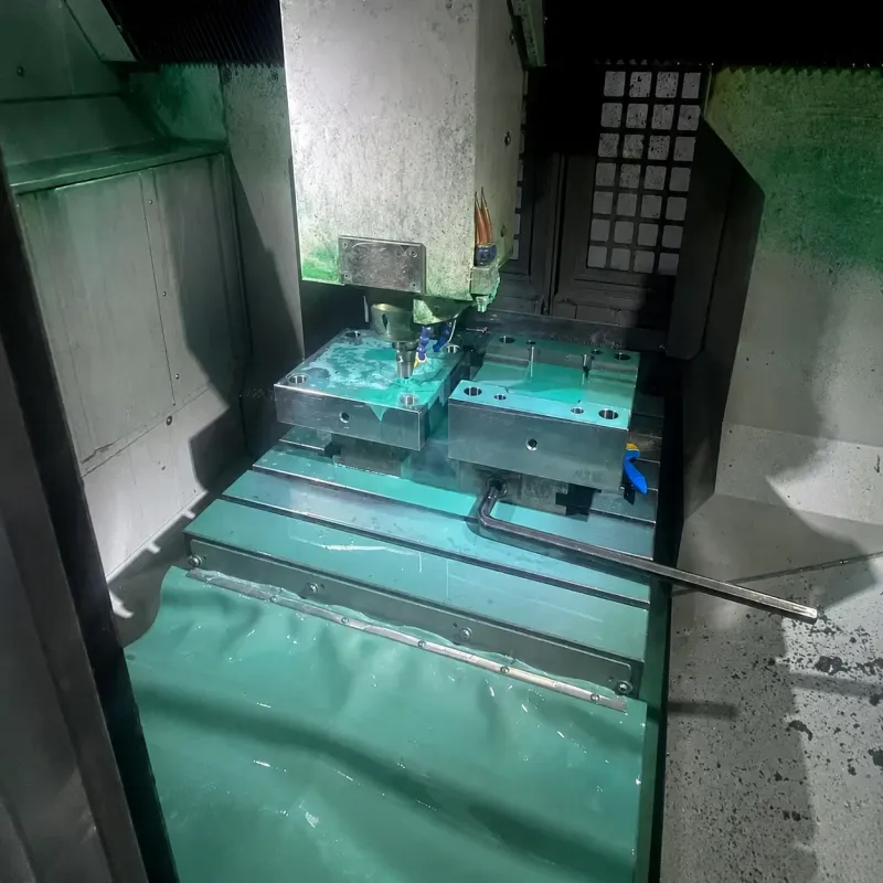
Draft does more work here than on a plastic tool. Use 0.5 to 1.5 degrees on a wall up to 50 mm tall and 2 to 3 degrees on a deep core. Add a 0.5 to 1 degree differential between core and cavity so the part stays on the side with the ejector system instead of being pulled toward the hot half. A part that sticks to the wrong half comes off on the next stroke and lands in the flash tray.
Eject hot. A phenolic part releases most cleanly between 140 and 170 degrees C, while it is still close to the mold temperature and before thermal contraction has tightened it onto the core. Let it drop below 100 degrees C in the tool and grip force climbs by 20 to 40 percent, which is often past what the pins can carry without chipping a corner.
Air is the cleanest release tool on a deep core. A poppet valve at 0.2 to 0.5 MPa for 0.5 to 2 seconds breaks the vacuum and the friction bond without touching the part, and on a 300 mm deep tube it can remove the need for any pin at all.
Shrinkage and Warpage Control
Thermosets shrink less than thermoplastics but they shrink in two stages. Chemical shrinkage happens as the network cross-links, and thermal shrinkage happens as the part cools from the mold to room temperature. The published figure covers both, and it is grade specific: phenolic 0.3 to 1.0 percent, epoxy 0.1 to 0.5 percent, melamine 0.4 to 0.9 percent, and BMC 0.05 to 0.5 percent with low profile systems at the bottom of that band.
Mineral and glass fillers move the number. A 40 to 60 percent mineral filled phenolic often lands between 0.2 and 0.5 percent, roughly half the unfilled value. That is why the cavity cannot be sized from a handbook table. Cut to the mid band of the supplier range, run 30 to 50 shots, measure a 100 mm section on a CMM, then adjust the cavity. The second cut is normally 0.05 to 0.20 mm of steel, so leave stock for it.
Warpage comes from three places: a cure gradient, fiber orientation and uneven ejection. A cure gradient across the part means one region finishes cross-linking while the other is still soft, so the two regions shrink against each other. A 10 degrees C spread across a cavity face is enough to bend a 200 mm flat panel by 0.3 to 0.8 mm. Fix that one on the thermal side before touching the tool geometry.
BMC and other fiber filled compounds add flow orientation. Glass fibers align along the flow front, and the part shrinks less along the fiber and more across it. Charge placement, gate location and flow length all steer that orientation. Where the part must stay flat, a shrink fixture that holds it during cooling from 160 to 60 degrees C is often cheaper than chasing the tool. For a high temperature service part, a post-cure of 2 to 16 hours at 120 to 160 degrees C stabilizes the dimension before machining.
Steel, Chrome Plating and Tool Life
Cavity steel in a thermoset tool has to hold a flash land at 0.05 to 0.15 mm for hundreds of thousands of shots at 150 to 180 degrees C. Through-hardened hot-work steel of the 1.2343 or 1.2344 ESR family at HRC 48 to 52 is the standard choice for this job, the same family used in die casting dies at a slightly lower hardness. Stainless 1.2083 at HRC 50 to 54 takes over where the compound is corrosive, which covers most phenolic grades.
Do not build a production land in pre-hardened P20 at HRC 30. A soft land peens under repeated closing pressure and opens from 0.10 to 0.25 mm within 200,000 shots. At that clearance even a viscous charge produces a 0.4 mm fin, and the fix is a full parting plane regrind rather than an adjustment. Mold geometry in this plant is held at 0.005 mm, and 0.002 mm on features cut by EDM or jig grinding, because a flash land is only as good as its flatness.
Plating does two jobs on a thermoset tool: release and corrosion resistance. Hard chrome at 0.02 to 0.05 mm is the workhorse on cavities and cores, and it strips and re-plates cleanly. Electroless nickel at 0.01 to 0.03 mm suits intricate geometry because it coats evenly, and gas nitriding at 0.05 to 0.15 mm hardens a shut-off edge without a dimensional change. Plan a re-plate at 200,000 to 500,000 shots and put the number in the tool file.
Watch the metals that ammonia attacks. Phenolic cure releases ammonia and water, and both react with copper alloys, so a beryllium copper core corrodes and leaves a green residue on the part. Keep copper out of the cavity surface or plate it.
Tool life follows the maintenance interval. A phenolic compression tool of good steel with a plated cavity and a maintained flash land runs 300,000 to 1,000,000 shots. Cleaning is the largest lever: remove cured flash from the land every 500 to 5,000 shots, clean vents each shift on a transfer tool, and inspect the parting plane at 50,000. Standard mold components ship in 3 to 7 days, and a full thermoset tool builds in 2 to 5 weeks.
Cavity Count Versus Press Tonnage
Cavity count starts with projected area and closing pressure, not with the platen drawing. For a compression tool, required force equals part projected area times 5 to 15 MPa. A 120 cm2 part at 10 MPa needs 120 kN per cavity. On a 2,000 kN press that is 16 theoretical cavities, and after the flash allowance and a plate utilization of about 80 percent, the practical answer is 12.
Transfer tools change the arithmetic in two ways. Pressure rises to 20 to 70 MPa, and the transfer pot cross-section adds to the projected area that the press must hold closed. A 12 cm2 pot on a 2,000 kN press consumes 240 to 840 kN by itself at 20 to 70 MPa, which can cost more cavities than the parts do. Size the pot to the shot volume plus a 10 to 20 percent cushion, because a pot that runs dry leaves a porous last cavity.
Platen size and parallelism then cap the count. Cavity pitch on a thermoset tool usually runs 100 to 150 mm to leave room for flash relief, ejector plates and heater access. A 900 mm by 600 mm platen therefore holds 6 by 4 positions at 150 mm pitch, and the tonnage needs to match that. Spec platen parallelism at 0.02 mm per 300 mm, because a 900 mm platen out of parallel by 0.05 mm opens one edge of every cavity by that amount.
Match the heater capacity to the cavity count as well. A 12 cavity tool on a 250 g shot consumes 3 kg of charge per cycle, and every gram has to be raised to 160 degrees C and held there. A press with 12 kW of platen heating will sag 5 to 10 degrees C on a fast cycle, and the cure time will drift by 20 to 40 seconds over a shift. Check the heat balance on the press before adding cavities to a proven tool, and check the mold base plate thickness and support pillar layout for the closing load at the same time.
Thermoset Mold Design FAQ
Q1. How deep should a compression mold flash groove be?
0.05 to 0.15 mm deep with a 2 to 5 mm flat land behind it and a 0.5 to 1 mm relief to atmosphere. That band holds the fin under 0.10 mm at 5 to 15 MPa. Anything deeper turns the land into a flow channel and produces a 0.3 mm fin that has to be deflashed by hand.
Q2. Why do phenolic parts have blisters even though the cure time is right?
Gas is trapped. Phenolic compounds release 5 to 8 percent of their weight as water vapor during cure. Add or lengthen a breathing stroke, 0.5 to 3 mm for 1 to 3 seconds at 3 to 15 seconds after closure, or pull vacuum at 50 to 100 mbar before the press closes fully.
Q3. Compression or transfer tooling for a part with metal inserts?
Transfer, in most cases. The cavity closes before material enters, so a terminal or a laminated core cannot shift. The trade is a cull and runner that add 10 to 25 percent to shot weight, plus a press that must hold 20 to 70 MPa instead of 5 to 15 MPa.
Q4. How tight should the cavity temperature be held?
Within 3 degrees C across the full cavity face at 150 to 180 degrees C, and within 3 degrees C between the upper and lower halves. That needs 60 to 100 mm platens, insulation between the hot half and the press, and a 45 to 90 minute warm-up before the first shot.
Q5. How long does a thermoset tool last?
300,000 to 1,000,000 shots in hardened steel at HRC 48 to 52 with a plated cavity. The number depends on maintenance: clean the flash land every 500 to 5,000 shots, clean transfer vents each shift, re-plate the cavity at 200,000 to 500,000 shots.
The Bottom Line
A thermoset tool succeeds or fails on five numbers: 150 to 180 degrees C held within 3 degrees C, a 0.05 to 0.15 mm flash groove with a 2 to 5 mm land, 5 to 15 MPa of compression pressure on projected area, a charge weight 3 to 10 percent over part weight, and a breathing stroke timed to the gas release. Hold those and phenolic, epoxy and BMC parts cure flat and flash-free.
Miss them and no press adjustment recovers the tool. A land that opened to 0.25 mm needs a regrind, a soft land needs a hardened insert, and a cure gradient from a 10 degrees C thermal split cannot be tuned out at the control panel.
DieStrike builds compression, transfer and precision injection molds to IATF 16949 with 0.005 mm mold accuracy, 0.002 mm on EDM and jig-ground features, cavity heat treatment up to HRC 62 and DFM feedback in 24 hours. The plant runs 120+ machines and supplies tier-1 programs at TE, Amphenol, Luxshare and Dongshan. Mold lead times run 2 to 5 weeks with standard components shipping in 3 to 7 days. If a thermoset program is on your roadmap, send the part drawing and the compound data sheet and we will return a tooling concept with a charge estimate and a cavity count before the drawing set is cut.
KEEP READING
Related Reading
Thermoset vs Thermoplastic: Mold Design Impact
Why a curing material needs a hot cavity and a cold feed system, and what that costs in tool architecture.
Read articleArticleHow to Design Transfer Dies
Pot sizing, runner length and gate land rules for tools that push material into a closed cavity.
Read articleArticleHow to Prevent Flash at the Parting Line
Land width, shut-off clearance and clamp stiffness numbers that stop a 0.05 mm fin from growing.
Read articleServiceMold Design and DFM Review
IATF 16949 tool engineering with DFM feedback in 24 hours and mold accuracy held at plus or minus 0.005 mm.
Read articleNEXT STEP
Ready to Start Your Mold?
Send us your element dimensions or part numbers — our team responds within 24 hours with pricing and lead time.

Written by
Ray ChanMold Buyer's Guide Author · Precision Mold Manufacturing Specialist. Ray helps global importers, distributors and OEMs source factory-direct molds and mold parts.