
How to Specify a Mold Base for ±0.002mm Tolerances
Table of Contents
A connector housing with a 0.002 mm flatness callout on its sealing face reaches T1 sampling and the first Cpk report reads 0.67, not 1.67. The cavity steel checks out — ±0.002 mm on a CMM, beautiful. The failure is in the frame: the mold was built on a catalog base with a sliding guide system that carries 10–20 µm of radial play, a support plate that flexes 20–40 µm under 80 MPa cavity pressure, and a 300 mm plate that grows 108 µm when the mold runs 30 °C hotter than the shop floor. Every one of those numbers is 5 to 50× larger than the ±2 µm tolerance you are trying to hold, and they stack. The result: a 500,000-piece connector program that needs 100% sorting, a six-figure quality bill, and a two-week delay while the base is rebuilt with ground matched guides. The mold base is not "just a frame" — it is the tolerance anchor of the entire tool. This guide walks through the eight specification points, the DME/HASCO/MISUMI decision, the plate-deflection math, and the verification clauses that get a ±0.002 mm tool built right the first time.
The Snapshot
- Three base mechanisms eat 5–50× your entire ±2 µm budget: guide play (10–20 µm), plate deflection (17–40 µm), thermal drift (60–108 µm).
- Specify ground matched guide sets at ±0.002 mm alignment (or preloaded ball guides at 0–2 µm play) — sliding H7/g6 fits give 7–20 µm of clearance you cannot afford.
- Plate deflection scales with thickness cubed: going 70 → 90 mm cuts deflection 2.1×; going 60 → 80 mm cuts it 2.4×.
- Hold base flatness to 0.02 mm per 300 mm and verify every plate with a CMM (±0.001 mm resolution) before cavity work starts.
- Standard series (DME/HASCO/MISUMI) keep standard parts at 3–7 day lead time; a complete precision mold built on that base runs 2–4 weeks — if the spec is right on the first RFQ.
Why the Mold Base Decides Whether ±0.002 mm Is Even Reachable
A mold base is the frame assembly that carries the cavity: top and bottom clamping plates, the cavity plate, the core plate, support pillars, the guide system, and the ejector assembly. It holds the two halves of the tool in a fixed spatial relationship for every one of hundreds of thousands of cycles. Everything that makes a part dimensionally correct — cavity geometry, shutoff position, wall thickness, draft — is defined relative to that frame. If the frame drifts, the part drifts.
Start with a tolerance budget. A ±0.002 mm part callout gives you a total window of 4 µm. That budget must be split across cavity and core machining, base alignment, thermal behavior, and process variation. A cavity machined to ±0.002 mm on a wire EDM is genuinely excellent — but it is already most of the budget. If the base then contributes 10–20 µm of guide play or 20–40 µm of plate flex, the stack-up is 10× over tolerance before the injection machine is even switched on. This is why precision molding failures so often trace back to the frame rather than the steel.
Two realities make the base the highest-leverage specification in a precision tool. First, it is repetition: the base defines the same relative position thousands of times per shift, and repeatability is what Cpk measures. A perfect cavity on a sloppy base produces a normal distribution centered correctly with a standard deviation larger than the tolerance — Cpk collapses. In precision injection molding, the base is where tolerances are won or lost before the cavity steel ever sees a cutter. Second, it is the cheapest thing to fix on paper: changing a plate thickness or guide class costs nothing at the RFQ stage, and weeks plus thousands of dollars after steel cutting. At DieStrike, base plates are machined to ±0.01 mm with 0.02 mm per 300 mm flatness and parallelism as the standard acceptance — that is the floor, not the ceiling, for a ±0.002 mm tool.
Three Ways the Base Wrecks (or Holds) Your Tolerance
| Mechanism | Where it comes from | Typical magnitude | Effect on the part | What fixes it |
|---|---|---|---|---|
| Guide play | Sliding leader pin/bushing fit (H7/g6 at Ø20 mm) | 7–20 µm clearance | Half-to-half shift, wall thickness variation, shutoff mismatch | Ground matched sets (±0.002 mm) or preloaded ball guides (0–2 µm) |
| Plate deflection | Support plate flex under cavity pressure | 17–40 µm at 80 MPa | Parting-line flatness loss, flash or incomplete shutoff, depth error | Thicker plates (deflection ∝ thickness⁻³), tighter pillar pitch |
| Thermal expansion | Mold grows with operating temperature | 60–108 µm on a 200–300 mm base | Dimensional drift through the shift, morning vs afternoon Cpk | Balanced ±1–2 °C circuits, matched thermal centers |
Guide play is the first thing to kill. A standard sliding leader pin with an H7/g6 fit at Ø20 mm has a clearance band of roughly 7–20 µm. For a ±2 µm part, that is 3–10× the entire budget, and it is bidirectional — the core half can sit left of center on one cycle and right on the next. Precision tools close that gap two ways: ground matched guide sets where pin OD and bushing ID are finish-ground together to ±0.002 mm alignment accuracy, and preloaded ball guides (caged-ball bushings with interference) that run at effectively 0–2 µm of play. At DieStrike, leader pins and bushings are hardened to HRC 58+, precision-ground to ±0.002 mm, and dimensionally interchangeable across HASCO/DME/MISUMI — so the precision upgrade is a catalog line item, not a custom part.
Plate deflection is the silent one. Under 60–100 MPa of cavity pressure, the support plate between two pillars bows like a beam. The deflection at typical pillar pitches and plate thicknesses lands at 17–40 µm — again an order of magnitude above the ±2 µm part tolerance — and it shows up as parting-line flatness loss, flash on one side and incomplete shutoff on the other. The fix is geometry: thicker plates and tighter pillar spacing (the math is in Section 5).
Thermal expansion is the one nobody writes down. Steel expands at roughly 12 × 10⁻⁶ / °C. A 300 mm base that runs 30 °C above the temperature at which it was assembled grows 108 µm — 54× the ±2 µm budget. Asymmetric cooling makes it worse: a hot core side and a cold cavity side bow the plates and walk the shutoff. Precision bases are specified with balanced cooling circuits held to ±1–2 °C and thermal centers that match the part's critical dimensions.
The 8 Specification Points for a Precision Mold Base
Every precision injection mold design should lock these eight decisions before steel cutting — each one is a line item a good mold builder will question if it is missing.
- 1. Overall size and cavity plan. The base footprint is the cavity array plus minimum wall stock — 40–60 mm between pocket and plate edge is the practical floor for precision work, more on large plates. Standard series run from 100×100 mm up to 1000×1000 mm; anything in that range is a catalog base, anything outside it is a custom plate at 30–50% premium.
- 2. Guide system. Specify the leader pin diameter (Ø20–Ø40 mm scales with base size), straight vs shoulder pins, and — for ±0.002 mm work — preloaded ball guides or ground matched sets rather than sliding fits. Add shoulder guides on any plate stack that carries heavy cores or asymmetric loading.
- 3. Plate material. P20 at 28–32 HRC is the economical default and what most standard bases ship with. 718H (P20 plus nickel) gives more uniform through-thickness hardness on large plates and better polishability. Clamping plates run S50C or 45#. Cavity and core inserts are a separate decision — hardened custom mold inserts in SKD61/S136 at HRC 48–62 mounted into the base pockets — and should never be lumped into "base steel."
- 4. Plate thickness. This is the deflection control (Section 5). Precision molds with cavity spans over 100 mm run 60–90 mm support plates; never less than pocket depth plus 30 mm. Thickness cubed is the lever: the math is cheap to run and expensive to ignore.
- 5. Pre-hardened state. Order plates pre-hardened (P20/718H arrive at 28–32 HRC) and machine after. Heat-treating a machined plate after the fact distorts it by 0.01–0.05 mm — enough to destroy the flatness spec. For wear-critical guide surfaces, specify nitriding: a 0.2–0.4 mm case at 950–1100 HV with no distortion.
- 6. Locating and interlocks. Dowel pins locate plates to each other; they do not resist opening forces. For ±0.002 mm shutoff work, specify taper interlocks (5–10°), side locks, or tapered alignment blocks that clamp the cavity halves into a zero-clearance position independent of the guide pins.
- 7. Cooling circuit allowance. Cooling holes, plugs, and baffles must be planned before plates are hardened or nitrided. Specify the circuit layout and a ±1–2 °C temperature balance target across the cavity — thermal symmetry is a tolerance spec, not a comfort spec.
- 8. Standard system and tolerance class. Declare the standard series (DME, HASCO, or MISUMI) and the tolerance class: standard ground vs precision ground. Put the acceptance numbers in writing — 0.02 mm per 300 mm flatness and parallelism, guide alignment at ±0.002 mm, CMM-verified.

DME, HASCO, or MISUMI: Picking the Standard Series
| Standard | Origin & dominant market | Typical size range | Guide system | Best fit |
|---|---|---|---|---|
| DME | North America; legacy inch-based tooling plus metric | 100×100 – 1000×1000 mm | Standard sliding, DME-style interlocks | US-built tooling, automotive and appliance |
| HASCO | Europe and Asia; metric | 100×100 – 1000×1000 mm | Sliding and shoulder guide series | European-spec molds, medical, precision housings |
| MISUMI | Japan / global configurable | 100×100 – 800×800 mm | Configurable incl. preloaded ball guides | Fast delivery, precision classes, tight-tolerance prototypes |
The three series are more interoperable than most engineers assume. Leader pins and bushings are dimensionally interchangeable across HASCO/DME/MISUMI, and plate sizes, pocket patterns, and ejector layouts follow overlapping grids — which is why a precision upgrade (ground matched guides, ball guides) can drop into a standard base without redrawing the frame. The practical choice is regional: DME if your plant and replacement parts live in North America, HASCO for European-spec programs, MISUMI when you want the configurable precision classes and short lead times. What matters for ±0.002 mm is not the brand on the plate but the tolerance class you specify inside that series — and the fact that custom bases cost 30–50% more than standard series, so start standard and go custom only when geometry demands it. DieStrike supplies both: standard series up to 1000×1000 mm, custom sizes and plate thicknesses machined to the same ±0.01 mm plate accuracy.
Plate Thickness and Deflection: Do the Math Before You Order
The governing equation for a support plate between two pillars, modeled as a simply supported beam under uniform load, is:
δ = 5·q·L⁴ / (384·E·I)
where q is the load per mm of plate width (cavity pressure × tributary width), L is the pillar pitch, E is the steel modulus (205,000 N/mm²), and I is the second moment of area (b·h³/12). Run it for a 120 mm pillar pitch, a 100 mm tributary width, and 80 MPa cavity pressure — typical for engineering plastics:
| Plate thickness h | Moment of inertia | Estimated deflection | vs ±0.002 mm budget |
|---|---|---|---|
| 60 mm | 1.80 × 10⁶ mm⁴ | 58.5 µm | 29× over |
| 70 mm | 2.86 × 10⁶ mm⁴ | 36.9 µm | 18× over |
| 80 mm | 4.27 × 10⁶ mm⁴ | 24.7 µm | 12× over |
| 90 mm | 6.08 × 10⁶ mm⁴ | 17.3 µm | 9× over |
Two things to take from this table. First, the absolute numbers are first-order estimates — real molds are stiffer (multiple pillars, bolted stacks, preload) — but the scaling is exact: deflection drops with the cube of thickness, so 70 → 90 mm gives 2.1× less flex and 60 → 80 mm gives 2.4× less. Second, even the best row in this table is 9× over a ±2 µm budget, which is the whole point: for ±0.002 mm work you do not rely on the support plate alone. You add support pillars at 120–150 mm pitch (more pillars beat thicker plates on cost), you preload the stack, and you keep deflection away from the cavity by locating the shutoff over the pillar grid. When a tool is truly critical, verify with FEA before cutting steel — a 30-minute simulation is cheaper than a re-ground plate.
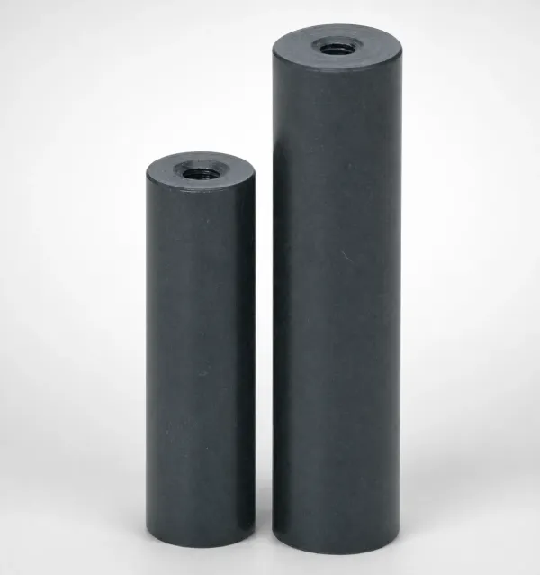
Mold Base Specification Table
| Base type | Size range | Precision class | Guide & alignment | Best suited for |
|---|---|---|---|---|
| Standard 2-plate (DME/HASCO/MISUMI) | 100×100 – 1000×1000 mm | Standard ground; flatness 0.02 mm/300 mm | Sliding leader pins, 10–25 µm play | General production, ±0.05 mm+ tolerances |
| Precision 2-plate | 100×100 – 600×600 mm | Ground matched; ±0.002 mm alignment | Preloaded ball guides or matched sets, 0–5 µm | Connector housings, ±0.002–0.01 mm features |
| 3-plate (stripper) | up to 800×800 mm | Standard or precision | Shoulder guides + stripper bolts | Top-gated parts, thin-wall components |
| Stack mold | up to 1000×1000 mm | Standard | Center guides + interlocks | High-cavitation thin parts |
| Custom interlocked | any, up to 1000×1000 mm | Precision; CMM-verified ±0.001 mm | Taper interlocks + preloaded guides | Medical, optical, high-Cpk ±0.002 mm programs |
Lead time is part of the spec: standard base parts ship in 3–7 days, and a complete precision mold — base, cavities, inserts, and trials — runs 2–4 weeks at DieStrike's 120+ machine facility under IATF 16949-level process control. The custom-interlocked row is the one to pick when the part drawing shows ±0.002 mm on a functional surface: it is the only row where alignment does not depend on clearance at all. And remember that mold bases and inserts are specified as a system — the base pockets, their cooling, and the insert geometry must be defined in the same drawing package, or the alignment that the base guarantees never reaches the cavity.
What ±0.002 mm Actually Demands From the Base
| Base feature | Specification | Why it matters | How to verify |
|---|---|---|---|
| Guide pins & bushings | Ground matched sets, ±0.002 mm, ≤0.8 µm Ra | Removes the 7–20 µm sliding fit | CMM on OD/ID, matched-set report |
| Plate flatness | 0.02 mm/300 mm, verified per plate | Parting-line shutoff and depth control | Surface plate + dial indicator sweep |
| Interlocks | Taper 5–10°, ground, zero clearance at shutoff | Locks cavity position independent of guides | Blue-check, feeler gauge at shutoff |
| Wear surfaces | Nitrided 0.2–0.4 mm case, 950–1100 HV | Geometry survives 500k+ cycles | Hardness test, case-depth check |
| Ejector guiding | 4 ground guide pins in the ejector plate | Repeatable, tilt-free ejection | CMM, straightness report |
| Thermal control | Balanced circuits, ±1–2 °C across cavity | Kills the 60–108 µm drift source | IR scan, flow-rate balance |
Each row is a specification you can audit. Ground guides: the pin OD and bushing ID are finish-ground together so the clearance band collapses from 7–20 µm to 2–5 µm, and preloaded ball guides take it to near zero — this is the single highest-value upgrade for a precision base. Nitriding gives the guide and interlock surfaces a 0.2–0.4 mm hard case at 950–1100 HV without the distortion of through-hardening, which is why it beats case-hardening on precision frames. Interlocks are what actually hold the ±0.002 mm position: a 5–10° taper lock pulls the two halves into the same position every cycle regardless of guide wear. Ejector guiding matters more than most engineers expect — a tilted ejector plate marks parts and shifts dimensions on thin ribs.
Verification is the part that gets skipped and the part that pays. At DieStrike every precision base is checked on CMMs at ±0.001 mm resolution, flatness is swept per plate, and the dimensional report ships with the base — so the ±0.002 mm claim is documented before the first cavity is cut, not discovered at T1. If your supplier cannot produce a base flatness and alignment report, they cannot hold ±0.002 mm for you either.
Writing the Spec Into Your RFQ and PO
A mold base RFQ that gets a ±0.002 mm tool built right contains seven clauses: (1) base size and standard series (DME/HASCO/MISUMI) with the exact plate dimensions; (2) plate materials and thickness per plate — P20 or 718H, 60–90 mm support plate; (3) guide system — pin diameter, straight vs shoulder, and the precision class (ground matched ±0.002 mm or preloaded ball guides); (4) interlock type and taper angle; (5) flatness and parallelism acceptance at 0.02 mm/300 mm; (6) cooling circuit layout and ±1–2 °C balance target; (7) deliverables — CMM report, flatness sweep, material certificates, and guide-play measurement. Read the full walkthrough in our guide on how to write a mold RFQ before you send it.
Two practical notes. First, run the free 24-hour mold design and DFM review before the RFQ goes out — a mold designer will catch a too-thin support plate or a wrong guide class on the drawing, which costs nothing, versus weeks after steel cutting. Second, budget the lead time honestly: standard base parts are 3–7 days, but a precision base with matched ground guides, interlocks, and a CMM report is a machining operation on its own — plan 2–4 weeks for a complete mold. A supplier that quotes a precision base like a catalog item is quoting you a sliding-fit base.
Frequently Asked Questions
| Question | Short answer |
|---|---|
| Can a standard catalog mold base hold ±0.002 mm? | Yes, if you specify the precision class inside the series — ground matched guides or preloaded ball guides, flatness verified at 0.02 mm/300 mm, interlocks fitted. The catalog base is the starting point, not the final spec. |
| P20 or 718H for the plates? | P20 (28–32 HRC) is the economical default. 718H gives more uniform hardness on large plates and better stability for long-run precision tools. |
| How thick should my support plate be? | Run the deflection formula (Section 5): 60–90 mm for precision molds with 100+ mm spans, and never less than pocket depth plus 30 mm. Thickness cubed is the lever. |
| Do I really need interlocks for ±0.002 mm? | Yes. Guide pins center the mold; they do not lock the shutoff. Taper interlocks (5–10°) give zero-clearance cavity positioning cycle after cycle. |
| Should I nitride the base plates? | On guide and interlock wear surfaces, yes — a 0.2–0.4 mm case at 950–1100 HV without distortion. Not needed on plain plate faces. |
| Can DieStrike build the complete mold on the base? | Yes — we machine cavities, cores and inserts onto our own bases for a complete precision mold build in 2–4 weeks, CMM-verified at ±0.001 mm. |
Your Action Roadmap
- 1. Pull the part drawing and list every functional surface with its tolerance — flag anything at ±0.01 mm or tighter; those features set the base class.
- 2. Run the deflection check (Section 5) and the thermal check (Section 2) before choosing plate thickness and cooling layout.
- 3. Write the eight specification points into the RFQ with the acceptance numbers and deliverables from Section 8.
- 4. Send it to a builder who can show you base flatness and alignment reports — and whose complete molds run 2–4 weeks, not twelve.
The risk is simple: a ±2 µm part on a base with 10–20 µm of play fails Cpk, and the sorting bill, the line-down, and the re-tooling come out of your margin. The fix is also simple — the base is the cheapest place in the mold to buy precision, if you specify it in writing. Send us your mold base specification for a precision-ground base with CMM report and a complete mold build in 2–4 weeks.
KEEP READING
Related Reading
5 Mold Cooling Channel Design Tips for Faster Cycles
Mold maker's 5 cooling channel design rules: channel-to-cavity distance 2-2.
Read articleArticle5 Shrinkage Compensation Rules for Mold Design
Shrinkage compensation decides mold accuracy. Five rules: material rates from 0.3% to 2.
Read articleArticle5 Ways to Reduce Mold Cost Without Cutting Quality
Five proven ways to reduce injection mold cost without cutting quality: DFM before quoting, right-sized cavity count,…
Read articleArticle7 Gate Design Best Practices for Balanced Filling
Mold maker's 7 gate design rules for balanced multi-cavity filling: gate depth 50-80% of wall thickness, land 0.5-1.
Read articleNEXT STEP
Ready to Start Your Mold?
Send us your element dimensions or part numbers — our team responds within 24 hours with pricing and lead time.

Written by
Ray ChanMold Buyer's Guide Author · Precision Mold Manufacturing Specialist. Ray helps global importers, distributors and OEMs source factory-direct molds and mold parts.