
How to Design Transfer Dies: Stations, Grippers and Automation
Table of Contents
A 280 mm structural bracket tool transfers clean at 24 strokes per minute until gripper jaw wear reaches 0.4 mm. Parts then land 1.2 mm off nest centre, the trim station cuts 0.3 mm into the flange, and 400 pieces run to scrap before anyone reads the tonnage monitor. A transfer die holds nothing but the part itself, so location lives in the gripper pocket, the lift height and a timing window measured in milliseconds. Get any of the three wrong and the tool scraps parts without ever showing a press fault.
The Snapshot
- Transfer tooling earns its cost from 1.5-2.0 mm strip upward, because thinner sheet cannot carry itself between stations without a carrier strip.
- Material utilization runs 60-75% on a transfer nest against 40-55% on a progressive layout, which on a 400 mm coil width returns 15-25% of annual steel spend.
- Station pitch on a multi-station transfer press lands at 150-700 mm, and every station needs 8-15 mm of clear edge per side for jaw entry at 0.5-2 mm clearance.
- Lift-and-carry height runs 20-80 mm to clear station nests, with the transfer motion held inside 120-270 degrees of slide rotation.
- The economics band for transfer tooling sits at 100k-2M parts per year, above tandem lines and below high-speed progressive tooling on small parts.
Why Transfer Dies Exist
A progressive die carries every part on the strip that made it. The carrier rails that hold that strip consume coil width, and on a 1.8 mm structural part the rails can be 30-60 mm wide per side. A transfer die deletes the carrier entirely. The blank is cut in the first station, then gripper rails or a robot lift the loose part from nest to nest through draw, trim, pierce, flange and restrike operations.
That single change drives everything else. Without a carrier, the die no longer needs a straight strip path, so nested blanks can be packed at any angle that suits the part outline. A 1.8 mm high-strength blank that would need a 380 mm coil in a progressive tool fits a 310 mm nest pitch in transfer. Scrap drops, coil width drops, and the press still delivers one finished part per stroke.

The cost of that freedom is part handling. A progressive tool locates the part with pilots that enter holes in the carrier strip at ±0.05-0.1 mm. A transfer die locates the part with nest pins, gripper jaws and hard stops, which lands closer to ±0.1-0.3 mm. Every design decision in the tool is a fight against that gap: stiffer grippers, deeper nests, slower transfer, more sensors.
Transfer tooling is the standard answer for automotive structural parts between roughly 300 mm and 2000 mm long, at 1.5-3.0 mm gauge, in annual volumes that will not pay for a full tandem press line. Cross members, seat frames, battery tray rails, suspension brackets and door impact beams all run this way. Above 2M parts per year on a small part, a progressive tool wins the arithmetic back.
Transfer vs Progressive: The Selection Criteria
Five inputs decide the route: strip thickness, part envelope, draw depth, annual volume and dimensional tolerance. Thickness comes first because it sets the whole case. A 0.6 mm connector shell has no stiffness to survive a gripper, so it stays in a carrier strip. A 2.0 mm bracket flexes under its own weight and survives transfer easily.
Material utilization then decides how much the carrier costs you. If the part outline wastes 35-45% of the coil in a progressive layout, the transfer saving can pay for a heavier tool inside 18 months. If the outline nests tightly already, the carrier adds little and progressive tooling stays cheaper.
| Selection input | Transfer die | Progressive die | Tandem press line |
|---|---|---|---|
| Strip or blank thickness | 1.5-2.0 mm and up | 0.2-3.0 mm, best at 0.5-1.5 mm | 0.8-2.5 mm |
| Stations in the tool | 4-12 | 8-30 | 4-6 separate presses |
| Strokes per minute | 12-40 | 60-400 | 8-15 |
| Material utilization | 60-75% | 40-55% | 65-80% |
| Tooling cost band | USD 400k-1.5M | USD 80k-400k | USD 600k-2.5M |
| Volume band per year | 100k-2M parts | 500k-20M parts | 30k-150k parts |
| Part envelope | 300-2000 mm long | under 400 mm typical | 500-3000 mm panels |
| Location method and accuracy | nest pins and jaws at ±0.1-0.3 mm | carrier strip and pilots at ±0.05-0.1 mm | robot re-grip at ±0.5-1.0 mm |
← swipe to scroll →
Table note: typical industry ranges for automotive structural stamping at 0.8-3.0 mm gauge. Cost and volume bands shift with part size, station count and steel grade.
Tolerance settles close calls. If the drawing calls for hole-to-hole position of ±0.15 mm across a 600 mm part, a transfer tool with hardened nest pins holds it and a tandem line will not. If the callout is ±0.05 mm on a 120 mm connector body, only a carrier strip tool with pilots is economical.
Station count is the last filter. Transfer dies carry fewer operations because each station costs a full nest plus 150-700 mm of press bed. Where a progressive tool runs 20 stations in a compact block, a transfer tool spreads the same work over 8 stations and two dies. Step-by-step build practice for the carrier-strip route is covered in how a progressive die is built, and the two workflows share toolroom discipline but almost no layout logic.
Material Utilization and the Cost Case
The transfer case is a steel bill. A progressive tool consumes coil equal to the full strip width times the feed pitch, including the carrier rails and the web between blanks. A transfer tool consumes a nested blank plus whatever skeleton the blanking station leaves behind. On large structural parts the gap between the two runs 15-25 points of utilization.
Put numbers on a real part. A 310 x 210 x 1.8 mm mild steel blank weighs 0.92 kg. A progressive layout at 55% utilization consumes 1.67 kg of coil per finished part. A transfer nest at 72% utilization consumes 1.28 kg. The difference is 0.39 kg per part.
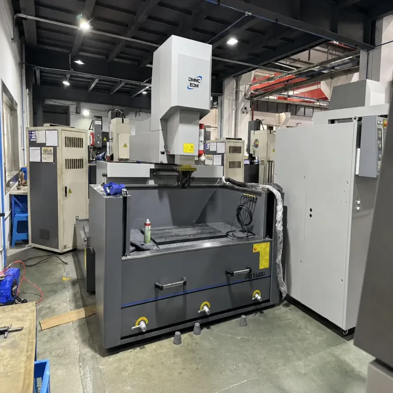
At 500,000 parts per year that gap equals 197 tonnes of steel. Cold rolled structural steel at USD 850 per tonne puts the saving near USD 168,000 per year, which is more than the incremental tooling cost of a transfer die over a progressive tool of the same station count. Two years of production and the nest has paid for the press bed it occupies.
Grade changes the arithmetic fast. A 1.8 mm DP600 or press-hardened blank at USD 1,200-1,800 per tonne makes each saved kilogram worth twice as much, so utilization above 65% becomes the deciding factor even when the volume would normally favour progressive tooling. That is why battery tray rails and seat structures at 2.0-2.5 mm gauge almost always go to transfer.
The catch is blanking scrap. Nesting at 72% is not free: the blanking station still leaves a skeleton of 25-30%, and the offal must be cut into chutes rather than pulled out as one continuous web. A poorly nested transfer layout can lose the whole advantage. Blank orientation, bridge width of 1.5-2.5 mm and the position of the coil edge relative to the cut all decide whether the saving is real.
Station Pitch and Die Layout
Station pitch is the centre-to-centre distance between adjacent nests. It must clear three things: the formed part plus its draw allowance, the gripper rail travel path, and the die section wall that carries each nest. On automotive structural tooling that lands between 150 mm and 700 mm. A 1.2 m cross member at 4 stations needs a bed around 5 m before any scrap chute is added.
Pitch should be uniform across all stations wherever possible. Uniform pitch lets one transfer bar index a fixed distance and keeps the cam law simple. Where a draw station needs more room, the layout pays for it twice: a longer die and a longer transfer travel per stroke. Every extra 100 mm of pitch adds roughly 0.03-0.06 s to the transfer movement at typical accelerations.
A four to six station sequence usually covers a structural part. Station one blanks and pierces the pilot or locating features. Station two draws or forms the main shape with a die cushion holding 20-40% of draw tonnage. Station three trims the flange and pierces secondary holes. Station four restrikes or flanges the edge. Station five handles a cam pierce or a notch. Station six sets the final form and may coin the mounting faces.
Beds and strokes scale with the part. A multi-station transfer press for 1.5-2.5 mm structural work typically runs 400-2500 tonnes with a slide stroke of 250-600 mm and a bed 2-6 m long. Clearance between upper and lower die at transfer height must reach 120-200 mm, because the part rises before it advances.
Coil-fed blanking inside the die is the preferred feed for high volume. The blanking station cuts from coil at 0.5-3.0 mm, drops the blank onto a nest or a walking beam, and passes the skeleton to a chopper or a scrap chute. Pre-cut stacked blanks suit lower volumes and heavier grades, but every stacked blank needs a destacker, a double-blank detector and a lubricator, which adds 15-25% to the line footprint.
Gripper Pockets and Part Handling
A gripper pocket is not a clearance cut. It is a datum. The jaw contacts the part edge over a defined length, holds it against a hard stop, and repeats that contact 500,000 times without wearing past 0.4 mm. Designing the pocket means designing the part edge that the jaw will grab.
Start with engagement length. Each jaw needs 8-15 mm of straight, burr-free edge to clamp, and a formed flange makes a poor grip face because it flexes. A flat grip face of at least 150 mm2 per jaw keeps contact stress under 10 MPa on 1.5-2.0 mm steel. Jaw clearance to the part runs 0.5-2 mm, enough to load without interference and tight enough to limit rattle at 20-40 strokes per minute.
Material choice follows the grip method. Hardened steel jaws with polyurethane pads at 60-90 Shore A handle 1.5-3.0 mm ferrous parts and grip 200-1500 N per pair. Magnetic grippers work on ferrous sheet above 1.0 mm and avoid marking, but lose 30-40% of their holding force once an oil film exceeds 0.05 mm. Vacuum cups suit aluminium and coated blanks, yet they need 0.2-0.6 bar of vacuum and a flat area that a drawn panel rarely offers.
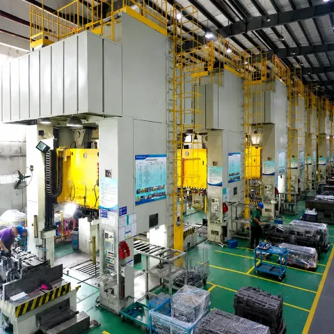
Part geometry dictates pocket placement before the die is designed. Put the grip on the flattest, stiffest, thickest section. Avoid a grip across a bend radius, because the part springs 3-8 degrees after forming and drags the jaw with it. On a drawn housing, grip the flange outside the draw radius. On a flat bracket, grip the two long edges and let the short edges float free.
Wear is the operational limit. Steel jaws in uncoated service lose 0.05-0.1 mm of face per 100,000 grips, so a jaw set that measures 0.4 mm oversize against its original bore is scrap. Track jaw wear with the same gauge you use for punch clearance, and replace in matched pairs. Mismatched jaw wear tilts the part, which then climbs one nest at an angle and trips the die protection sensor two stations later.
Lift-and-Carry Timing and Synchronisation
Transfer is a three-axis motion: lift, advance, lower, then return below the die face. All of it must finish while the upper die is clear, and the whole window sits inside 120-270 degrees of slide rotation on a typical mechanical press. Miss that window by 10 degrees and the transfer bar collides with a die section at 25 strokes per minute, which is a tool disaster rather than a scrap event.
Lift height is the first number. A part must rise 20-80 mm above the nest face to clear station pilots, restrike pads and any cam return. Draw parts with a 200 mm depth need the higher end because the forming punch cannot retract into the part faster than the transfer advances. Everything above the minimum lift costs cycle time, since lift distance scales with transfer time.
| Transfer parameter | Mechanical cam transfer | Servo transfer |
|---|---|---|
| Pitch range | fixed 150-700 mm, set by drive box | programmable 100-800 mm |
| Positioning repeatability | ±0.2 mm | ±0.05-0.1 mm |
| Pitch change for a new die | gear or cam change, 2-8 h | program entry, 5-10 min |
| Transfer time per stroke | 0.6-1.5 s | 0.4-1.2 s |
| Typical strokes per minute | 10-25 | 15-40 |
| Motion law | fixed, set by cam profile | tunable, 2-4 g peak acceleration |
| Stall or jam behaviour | shear pin or torque limiter trips | drive torque limit and fault stop |
← swipe to scroll →
Table note: typical figures for multi-station transfer presses in the 400-2500 tonne class. Servo transfer usually carries a 20-35% higher press price and pays back through faster die change.
Servo transfer changes the changeover economics more than the cycle time. A cam transfer must be re-geared for every new pitch, which takes 2-8 hours of maintenance time. A servo bar accepts a new pitch as a program value in 5-10 minutes, so a plant running four different structural parts can move between them inside one shift.
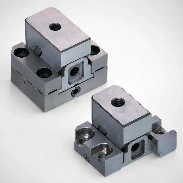
Timing is verified, not assumed. Tape a strip of clay or a soft aluminium slug into each nest, run the press at 5-10 strokes per minute in inch mode, and measure the crush depth. A clean nest shows zero contact. Any mark means the window is tight and the transfer must be advanced or the slide phase shifted. Do this before the first production stroke, because a 0.5 mm interference at 20 strokes per minute destroys a hardened nest insert in under a minute.
Multi-Station Press vs Tandem Line
A transfer die fits one press. A tandem line spreads the same operations across four to six separate presses linked by robots or conveyors. Both handle large structural parts and both cost more than a progressive tool. They differ on cycle time, tooling cost, floor space and how badly the line behaves when one station stops.
The transfer press runs 12-40 strokes per minute with every operation inside one die set, so one operator loads coil and one finished part leaves each stroke. A tandem line runs 8-15 strokes per minute because each robot transfer costs 1.5-3.0 s and the part must be re-gripped at ±0.5-1.0 mm. That re-grip accuracy is why tandem lines suit panels and closures better than assemblies with tight hole patterns.
Tooling cost splits the other way. A transfer die at USD 400k-1.5M sits below a five-press tandem tool set at USD 600k-2.5M, and it occupies one press rather than five. Against that, a tandem line degrades gracefully: if press three needs a two hour repair, presses one, two and four can hold work in process and the line restarts without scrapping the queue. A transfer press stops the whole line on any station fault.
Floor space and building height usually decide the last vote. A 2500 tonne transfer press with a 6 m bed needs a pit, a crane rated above the die weight and 1200-1800 m2 of surrounding cell. A tandem line of five smaller presses needs two to three times the length and a robot between each pair, which in a brownfield plant rarely fits.
Volume is the final filter. Under roughly 100,000 parts per year the tandem line wins, because the presses are smaller, the dies are cheaper individually and the line can be built in stages. Between 100,000 and 2,000,000 parts per year one transfer die on one press returns the lowest cost per part. Above 2M parts per year on a part under 400 mm, high-speed progressive tooling takes over, a route covered in high-speed lamination and progressive tooling.
Deep-Drawn and Tall Part Transfer
A drawn part is where transfer beats progressive outright. In a carrier strip tool, a 200 mm deep cup must be surrounded by strip through every draw stage, which wastes coil and limits the draw to shapes the strip can survive. A transfer tool draws one loose part per station and never needs the strip to fold.
Draw depth sets the station count. A deep drawn housing from a 320 mm blank to a 140 mm diameter runs a 2.3:1 first draw, then one or two redraws at 1.25-1.35:1. That is three stations plus a trim and a pierce, or five in the tool. Each draw station needs a die cushion delivering 20-40% of punch load, and the transfer must lift the cup clear of the punch nose before advancing.

Gripping a drawn part is the difficulty. The flange is the only flat surface early in the sequence, and it shrinks with every draw until it becomes a wall. Design the pocket on the flange for the first three stations, then hand the part to a wall grip or a vacuum support for the rest. If no flange survives, the part enters the tool as a blank and must be gripped on the wall at 0.5-2 mm clearance with a jaw that follows the wall taper.
Orientation matters more than for a flat part. A cup transferred upright holds lubricant and cannot be unloaded by gravity. Most deep drawn transfer tools transfer the cup inverted after the last draw, using a turnover station or a cam-driven flip, so the part drops out of the die mouth at the end. That single extra station costs 150-400 mm of bed and removes the need for a pick-out robot.
Thinning control carries over from any draw operation. Wall thinning past 20% of nominal thickness is a reject, so transfer stations must hold 0.85-0.95t clearance on ironing passes and re-lubricate between draws. Draw ratio limits, blank holder pressure and stage allocation are the same physics described in deep draw die design, and the transfer tool simply moves each stage into its own nest.
Blanking, Nest Location and Piloting
With no carrier strip, the blank itself must be cut accurately and located absolutely. The blanking station in a transfer die sets the datum for every downstream station. If the blank leaves station one 0.4 mm out of position, every hole in the finished part moves with it, and no amount of gripper adjustment recovers the error.
Nest location does the work that pilots do in a progressive tool. Use two to four hardened nest pins or rest pads per station, with the primary locating pair on a diagonal. Nest surfaces are ground flat within 0.02 mm and hardened to HRC 58-62, matching the insert hardness used across our tooling. Locating pins are typically 8-16 mm diameter with a 15-20 degree lead chamfer so a part arriving 0.5 mm off centre still slides home.
Ejection and part-present sensing close the loop. Every station needs a positive exit: air blast for light parts, a spring or nitrogen knock-out for heavy ones. A part left in a nest at 25 strokes per minute is crushed on the next stroke and usually takes a die section with it. Fit an inductive or photoelectric part-present sensor at each nest and wire it to the die protection channel, with the press stopping on the second consecutive miss rather than the first, which keeps nuisance stops under 2% of production.
Tonnage monitoring adds the second safety net. Record a signature for each station across 20 good strokes, then set the alarm window at ±5%. A slug pulled into the die, a missing lubricant film or a doubled blank all change the curve before they change the part, so the monitor is usually the first system to flag a problem.
Die Steel and Wear Points
Transfer dies wear in predictable places. Cutting edges take abrasive wear, draw radii take galling, nest pads take impact, and gripper jaws take sliding wear. Each point wants a different steel, and mixing them up is the most common cause of a tool that needs regrinding at 120,000 strokes instead of 500,000.
Punches and die buttons for 1.5-3.0 mm steel run D2 at HRC 58-62 for volumes under 300,000 parts, A2 where shock loading dominates, and PM-HSS or carbide above 1M strokes on high-strength grades. Cutting clearance sits at 5-10% of thickness per side, and the burr height it produces is the acceptance criterion: 0.05 mm on a sheared edge at 2.0 mm thickness is normal, past 0.1 mm the clearance has opened or the edge has worn 0.15 mm.
Draw radii and bead faces are galling risks. Polish to Ra 0.2-0.4 micrometre, or apply a TiCN or AlCrN coating at 2-5 micrometre thickness when drawing 1.5-2.5 mm high-strength steel. Nitrogen gas springs, hardened guide posts and bushings and ball-lock punches all come from the standard parts channel, which is why a tool that needs a replacement punch can be back in production in days rather than weeks. Punch clearance and sharpening intervals are covered in punch clearance maintenance if the tool shares that hardware.
Nest and gripper wear deserves its own budget line. Nest pads are consumables: expect to replace 15-25% of them per year on a two shift line, more where the part arrives hot or oil-laden. Track them by station so a repeat wear pattern points at a transfer timing problem rather than bad steel.
Cost per Part and the Volume Band
The transfer decision is an amortization calculation. A USD 800,000 transfer die spread over 500,000 parts contributes USD 1.60 per part. Spread over 200,000 parts it contributes USD 4.00. The saving in material, meanwhile, stays near USD 0.33 per part at USD 850 per tonne steel and a 0.39 kg difference between nest and strip.
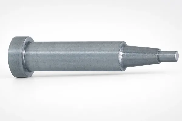
Conversion cost runs the other way. A transfer press at 24 strokes per minute delivers 1,440 parts per hour, and a USD 180-250 hourly rate puts machine time at USD 0.13-0.17 per part. A progressive tool at 180 strokes per minute produces 10,800 parts per hour for a lower rate per part, which is exactly why high-volume small parts stay on a carrier strip.
The break-even band sits at 100,000 to 2,000,000 parts per year. Below 100,000, a tandem line with cheaper individual dies and staged investment beats a transfer press, because tool amortization dominates everything else. Above 2,000,000 parts per year on a part under 400 mm, progressive tooling delivers a lower total cost even after 20-25 points of extra material scrap.
Three secondary costs decide marginal cases. First, press availability: a transfer line typically runs 80-88% uptime against 85-92% for a single progressive press, so the transfer case needs 5-8% more machine capacity in the plan. Second, die maintenance: a transfer tool usually needs a full service every 250,000-500,000 strokes. Third, capital timing: a transfer press is a single USD 1.5M-8M purchase, while a tandem line can be added press by press as volume grows.
Tooling for the route is built to die accuracy of ±0.005 mm with component geometry held at ±0.002 mm, and a DFM review comes back within 24 hours. A transfer die with 6-8 stations typically quotes at 2-5 weeks of engineering and build lead time depending on size, so the delivery clock is not the constraint that a volume decision usually is. Stamping die manufacturing capability is set out on the stamping die manufacturing page.
Die Change, Maintenance and Safety
A structural transfer die weighs 5-40 tonnes. Moving it is a production activity, not a maintenance event, and the changeover design decides how much of the press capacity is available for revenue. Quick-change practice with hydraulic clamping, a die cart and pre-heating brings a changeover from 2-8 hours down to 30-60 minutes on comparable presses.
Repeatable clamping matters more than speed. Hydraulic clamps set to 150-250 bar hold the lower die without distortion, and dowel registers or hydraulic positioning pins return the die to within 0.05 mm of its previous position. Without that register, every changeover forces a full first-off inspection and a 30-60 minute setup loop, which erases the gain from the cart.
Maintenance intervals follow the wear map. Inspect gripper jaws and nest pads every 50,000 strokes, check punch edges and clearances every 100,000, and plan a full die service at 250,000-500,000 strokes. Sharpening removes 0.2-0.5 mm per pass, so a punch with a 6-10 mm usable body supports 10-20 regrinds before replacement. Standard parts such as punches, springs, guide posts and bushings ship in 3-7 days, which keeps a planned service inside a weekend shutdown.
Safety is governed by press guarding standards, not by die design alone. EN ISO 16092-1 covers press safety requirements and ISO 13849-1 sets the performance level for the control functions that stop a hazardous motion, with PL d the normal target for a guard interlock on a transfer press. Practical layers include light curtains on the load openings, two-hand control for inch mode, safety blocks rated above the die weight before anyone reaches under a suspended slide, and lockout procedure on the transfer drive before jaw adjustment. On US installations, 29 CFR 1910.217 remains the reference for mechanical power press guarding and inspection.
Two design habits remove most human risk before the guard even matters. First, keep gripper adjustment reachable from the operator side with the slide blocked, so nobody leans across the bed. Second, put every part-present sensor and clamp position in the die protection logic, so the press cannot stroke into a condition that would throw a part out of the die. A plant with those two habits rarely records a transfer related injury.
FAQ
Q1. When is a transfer die better than a progressive die?
When the part is large, 1.5-2.0 mm thick or heavier, and the carrier strip would waste 15-25% of the coil. Transfer tooling also wins when the part is drawn to a depth that a carrier cannot follow.
Q2. What strip thickness can a transfer die handle?
The practical floor is 1.5-2.0 mm for automotive structural work, because thinner sheet buckles under gripper load and loses position. Thicker grades up to 3.0-4.0 mm transfer well but need higher jaw force and slower strokes.
Q3. How much material does a transfer die save?
Typical utilization runs 60-75% against 40-55% on a progressive layout. On a 1.8 mm structural part that difference is around 0.39 kg per part, or 197 tonnes per year at 500,000 parts.
Q4. What annual volume justifies a transfer press?
Roughly 100,000 to 2,000,000 parts per year. Below that band a tandem line is cheaper to build and stage. Above it, a multi-station transfer press or high-speed progressive tooling returns the lower cost per part.
Q5. Can a deep drawn part run in a transfer die?
Yes, and it is often the better route. Each draw stage gets its own station at 2.3:1 first draw and 1.25-1.35:1 redraws, with jaw grips moved from the flange to the wall as the flange shrinks.
Q6. How is part position held without a carrier strip?
Two to four hardened nest pins per station, ground within 0.02 mm, hold the part at ±0.1-0.3 mm. Part-present sensors and tonnage monitoring at ±5% catch a part that has shifted before the next stroke.
The Bottom Line
Transfer dies trade carrier strip for part handling, so they win on material utilization and lose on location tolerance. Above 1.5-2.0 mm thickness and 100,000 parts per year, the nest usually pays. Below those numbers the carrier strip still wins. Set gripper pockets, lift height and transfer timing before the first block is cut, because those three numbers decide whether the tool runs 24 strokes per minute or scraps parts quietly. Send drawings to our engineering team for a DFM review within 24 hours.
KEEP READING
Related Reading
How to Build a Progressive Die (Step by Step): 8 Steps
Strip layout, station sequence and the build steps that keep a progressive tool on schedule and on tolerance.
Read articleArticleHow to Design Deep Draw Dies: Draw Ratio, Wrinkle Control and Stages
Draw ratio limits at 1.8-2.2:1, blank holder pressure and stage allocation for cups and housings.
Read articleArticleDesigning EV Motor Lamination Dies: High-Speed Progressive Tooling
Lamination dies run at 200-400 strokes per minute with carbide punches and tight burr limits.
Read articleServiceStamping Die Manufacturing
Transfer, progressive and deep draw tooling built to ±0.005 mm die accuracy with 2-5 week lead times.
Read articleNEXT STEP
Ready to Start Your Mold?
Send us your element dimensions or part numbers — our team responds within 24 hours with pricing and lead time.

Written by
Ray ChanMold Buyer's Guide Author · Precision Mold Manufacturing Specialist. Ray helps global importers, distributors and OEMs source factory-direct molds and mold parts.