
How to Design Deep Draw Dies: Draw Ratio, Wrinkle Control and Stages
Table of Contents
A 1.0 mm DC04 cup die that runs clean on a 300 mm blank tears at the punch nose when coil hardness drifts 12% high. The same tool wrinkles at the flange when cushion pressure falls from 2.0 MPa to 1.4 MPa. Both defects sit inside the draw ratio window. Both are settled in the die, not on the press. A deep draw tool either fails in the first 20 strokes of tryout or runs 500,000 strokes without a tear. The difference sits in five numbers: draw ratio, blank holder force, radii, clearance and stage count.
The Snapshot
- First-draw ratio caps at 1.8-2.2:1 on deep drawing quality steel, and each redraw adds a maximum of 1.3:1 per pass at 1.0-1.6 mm thickness.
- Blank holder pressure runs 1.5-2.5 MPa on 1.0 mm mild steel and 2.5-4.0 MPa on stainless and AHSS, applied over the ring area outside the die radius.
- Draw clearance sits at 1.1-1.2t per side on the first draw and drops to 0.85-0.95t on ironing stations that size the final wall.
- Draw beads add 10-30% to punch load and keep the flange in tension, which is the reliable cure for flange wrinkles on rectangular and panel parts.
- Wall thinning past 20% of nominal thickness is a reject, so blank size and stage count must be locked before the first block is cut.
Why Draw Ratio Decides the Tool
Draw ratio is blank diameter divided by cup diameter for one operation. A 200 mm blank formed into a 100 mm cup runs 2.0:1. Every deep draw program reduces to that figure, because the ratio sets the circumferential strain the flange must absorb during a single stroke.
Strain capacity is material specific. Deep drawing quality steel such as DC04 carries an n-value of 0.20-0.24 and an r-bar of 1.6-1.9 typical, so it holds a 2.0:1 first draw. A 1.2 mm DP600 sheet carries an n-value of 0.12-0.14 and an r-bar close to 1.0, so its first draw caps near 1.6-1.8:1. Stainless 304 at 0.9-1.5 mm lands between the two, but it work hardens fast, which is why the same part often needs one more station in 304 than in mild steel.

Stage count follows from the ratio chain. A 1.0 mm mild steel housing from a 200 mm blank to a 60 mm final diameter needs 3.33:1 overall. At 2.0:1 on the first draw and 1.3:1 per redraw, three forming stations deliver 200 mm to 100 mm to 77 mm to 59 mm. A fourth station then sizes the wall and holds the diameter within ±0.05 mm.
Press tonnage is an output, not an input. Punch load for a cylindrical cup runs near F = π × d × t × σ_UTS × 0.7. A 100 mm punch at 1.0 mm on 350 MPa steel needs about 110 kN. Blank holder force adds 75 kN of typical cushion load, and friction adds another 20-35%, which puts the working load near 200 kN or 20 tonnes. Press selection still hinges on blank size and stroke first, since a 250 mm blank needs a bed and cushion rated for it.
First-Draw Limits: 1.8-2.2:1 and Where It Comes From
The limiting draw ratio is measured, not calculated. A strip of the actual coil is drawn through progressively smaller dies until the cup fractures, and the last successful ratio becomes the design limit. For 1.0-1.6 mm deep drawing quality steel, that limit lands at 1.8-2.2:1 in shop practice. The published 2.2:1 figure assumes a clean blank edge, a polished die radius and a lubricant film that survives the full stroke.
Three inputs move the limit. Higher r-bar raises it, because the flange resists thinning in the wall direction. Greater thickness raises it, at roughly 0.05 ratio points for every extra 0.5 mm of sheet. A thicker blank also suppresses flange buckling, and a t/D ratio above 0.01 is the usual floor for a wrinkle-free first draw.
| Material at 1.0-1.6 mm | First-draw ratio | Redraw ratio per pass | Clearance per side | Blank holder pressure |
|---|---|---|---|---|
| DC04 / DC06 mild steel | 1.8-2.2:1 | 1.25-1.35:1 | 1.10-1.20t | 1.5-2.5 MPa |
| DP600 AHSS | 1.6-1.8:1 | 1.15-1.25:1 | 1.15-1.25t | 2.5-4.0 MPa |
| Stainless 304 | 1.6-1.8:1 | 1.15-1.30:1 | 1.15-1.25t | 3.0-4.0 MPa |
| Aluminium 5052-H32 | 1.5-1.8:1 | 1.20-1.30:1 | 1.10-1.20t | 1.5-2.5 MPa |
| Copper C110 | 1.8-2.0:1 | 1.25-1.35:1 | 1.10-1.20t | 1.5-2.5 MPa |
← swipe to scroll →
Table note: figures are typical shop ranges for 1.0-1.6 mm sheet with a polished die radius. Confirm against a strip draw test on the production coil before releasing the die design.
Cup height is the second limit. A flat blank drawn without a redraw reaches an h/d of 0.6-0.75 typical, and taller cups need drawn-in material from a larger blank or a redraw station. Parts that exceed h/d = 0.75 in one hit usually tear at the punch nose instead.
Blank Holder Force and Wrinkle Control
Wrinkles form because drawing puts the flange in circumferential compression. Thicker material resists that compression, so a 0.8 mm blank wrinkles at pressures where a 1.5 mm blank stays flat. Blank holder force is the direct control on that behaviour, and it must be high enough to flatten the flange and low enough to let metal flow inward.
Calculate it from the ring area. For a 250 mm blank drawn to a 120 mm cup with an 8 mm die radius, the ring area is about 37,400 mm². At 2.0 MPa, holder force is 74.8 kN, or 7.6 tonnes. That figure is the starting point, not the answer, because the flange thins as the stroke continues and the effective contact area shifts.
Set the pressure from tryout, not from the drawing. Start 30% below the calculated value and raise it in 10% steps until the flange sits flat. A wrinkle taller than half the sheet thickness is a reject, since it will fold into the wall on the next pass.
Too much holder force produces the opposite failure. Punch load rises with friction, the wall thins under the die radius and the cup fractures near the bottom radius. Stainless and AHSS tolerate less of that window, which is why 304 parts run 3.0-4.0 MPa with a heavier lubricant film and a larger die radius.
Hardware matters as much as the pressure number. A cushion or nitrogen system holds force through the full stroke, while coil springs lose 20-30% of preload as they compress. An uneven holder plate above 0.05 mm out of flat will wrinkle one corner of the flange and tear the opposite one. Check plate flatness and shim stacks of 0.05-0.20 mm before the first tryout pass.
Draw Beads and Material Flow Control
A draw bead is a ridge in the holder plate that forces the sheet to bend and unbend as it flows inward. That detour adds restraint the way a brake adds drag, and it adds 10-30% to the punch load. Beads exist because a flat holder cannot control flow across a large or rectangular blank, where material at the corners travels further than material at the sides.
Typical geometry runs 3-6 mm of bead height with a 3-5 mm bead radius on an 6-12 mm wide ridge. Smaller radii restrain harder and mark the panel but raise the risk of galling on stainless and coated stock. Beads are normally machined into replaceable inserts in D2 or PM steel, since a bead face wears faster than the die radius and takes the worst of the sliding contact.
Use beads as the tuning lever. Grinding 0.2-0.5 mm off a bead height in tryout shifts flow toward that region. Adding a lock bead at a corner pulls material tight where a panel would otherwise pull in and wrinkle. Three passes of bead adjustment usually replace a full simulation iteration in shop time and cost far less.
Two rules keep bead tuning from turning into scrap. Keep the bead radius polished to Ra 0.4 µm or better, and keep pressure at the bead below the level where the sheet thins past 15%. On a panel with a class A surface, bead marks must sit outside the visible zone or be sized below 0.02 mm of print depth.
Punch and Die Radii Plus Clearance at 1.1-1.2t
The die radius is where the sheet bends and unbends, and it decides whether the cup tears or wrinkles. A radius below 2t concentrates strain and splits the wall at the punch nose. A radius above 10-12t stops restraining the flange, so wrinkles travel inward with the material. Working values for a first draw on 1.0-1.6 mm mild steel run 4-8t, and 6-10t on stainless and AHSS where strain tolerance is lower.
Punch nose radius follows the same logic but with a shorter arc. Use 4-8t on a first draw, 2-4t on a redraw and 1-2t on a final sizing pass. A generous punch radius at the bottom corner lowers the local strain. A small punch radius in the last station helps hold bottom flatness inside the ±0.05 mm band most housings need.
Clearance is the second control point. Draw clearance at 1.1-1.2t per side leaves enough room for the wall to thicken as it flows. Clearance at 1.0t or below starts ironing the wall on the first draw, which raises punch load and thins the material below nominal. Clearance above 1.3t lets the wall buckle and produces a loose fit on the punch.
Surface finish on the radius matters as much as the geometry. Keep draw radii at Ra 0.4 µm or better on steel, and Ra 0.2 µm on stainless, aluminium and coated stock. A radius that measures correct but shows a 0.02 mm axial tool mark will gall within 5,000-20,000 strokes. Once galling starts, metal transfers from the sheet to the die face until the radius grows enough to change the flow.

Spotting confirms what the drawing cannot. Blue check on the die radius should show 75-85% contact around the full contour. A pocket of light contact on one side shifts material flow and shows up later as earing or a wall thickness swing. Shim and re-spot before the next pass rather than adjusting the press.
Stage Allocation: Draw, Redraw, Ironing
Stage count turns a total ratio into a workable tool. Split the total ratio so no single station exceeds its limit. Take a 200 mm blank to a 60 mm cup at 3.33:1 overall. The first draw takes 2.0:1 and each redraw takes 1.3:1, which gives 200 mm to 100 mm to 77 mm to 59 mm in three forming stations. A fourth sizing station then brings the diameter to 60 mm ±0.05 mm.
Give the first draw the largest share. Blank material is softest and most formable at that point, and later stations work a strain-hardened wall. A chain of equal 1.5:1 stations is a common design error, since the last station then works the hardest material at the smallest radius and fractures.
Station type differs at each step. The first draw station needs a cushion-driven blank holder. A redraw station often uses a spring or nitrogen pressure pad sized at 30-50% of the first station force. An ironing station runs a reduced clearance of 0.85-0.95t, which thins the wall 5-15% and packs it to a uniform thickness across the 8 clock points a first article check samples.
Layout depends on the part and volume. A deep drawn housing normally runs on a transfer press or as separate draw dies with manual or robot transfer between them. A progressive strip has to stay connected, and drawn parts rarely allow that. Progressive deep draw tooling exists for small parts with a strip carrier, and those layouts need station pitch of 1.5-2.0 times the part diameter to clear the drawn height.
High work hardening materials need an extra step. Stainless 304 and some aluminium grades harden past the point where further reduction cracks the wall after roughly 60-70% total reduction. Those programs insert an anneal between draw stages, which means a second tool set and a longer process chain. Builders quote that schedule separately, and it usually adds 2-4 weeks against a straight three-stage die.
DieStrike builds deep draw stages under one tool number with shared guide pins and die sets, which keeps station alignment inside ±0.005 mm through the run. Lead time on stamping die manufacturing runs 2-5 weeks from released drawing to T1.
Thinning Limits and Wall Thickness Control
Wall thickness is the pass or fail number on a drawn part. Measure a first article at 8 points around the wall, at the bottom radius and at the mid-wall, then compare against nominal. A 10% deviation from nominal thickness is normal on a well-set draw. Past 20% thinning the wall is a reject, since the section has lost strength and the next station will finish the tear.
The bottom radius is the thinnest point in the part. Material there is stretched biaxially, and the wall on the outside of the punch nose carries the highest strain in the whole sequence. A first article measuring 0.9 mm on 1.0 mm nominal at the bottom radius sits at the edge of the window. A coil with 8% less total elongation will push it past the limit.
Clearance, friction and lubricant all move the thickness number. Tight clearance irons the wall and thins it. Heavy friction at the die radius raises the punch load and stretches the wall. High-viscosity or chlorinated EP lubricant on stainless lowers local friction enough to recover 3-8% of wall thickness at the radius on a marginal part.
Earing is the second thickness-related defect. A rolled sheet with r-bar of 1.6-1.9 draws faster along the rolling direction and leaves 4 ears of 2-6% of cup height on steel, and up to 10% on aluminium. Most programs accept the ears and trim them at a following station. Complex profiles can be improved by nesting blanks or rotating the blank 45 degrees to the rolling direction, which shifts where the ears land.
Strain measurement settles the argument when the press and the die are both suspected. Etch a 10 mm circle grid on the blank, run 10 parts and measure the deformed circles. Major strain values above 70-80% of the forming limit curve for the grade mean the design runs on the edge. A one-stage change is cheaper than the scrap rate across 500,000 hits.
Die Steel and Surface Treatment for Deep Draw Dies
Deep drawing dies fail on sliding wear and galling, not on bulk fracture. The die radius, the bead faces and the punch nose see continuous contact at 1.5-3.0 MPa of interface pressure. Those working surfaces need hardness, low friction and a finish that stays polished through the run. Body plates and holders run a lighter duty at 280-320 HB and can use softer material.
D2 at HRC 58-62 remains the default for draw radii and bead inserts, with a wear life of 150,000-400,000 hits between rework typical. Powder metallurgy grades such as CPM 10V or Vanadis 8 at HRC 60-64 hold 2-4 times that life on abrasive or coated stock, at 2-3 times the material cost. Cemented carbide inserts suit volumes above 2 million hits. They need a guided punch and careful handling, because edge chipping on a carbide radius means a full insert replacement rather than a polish.
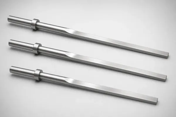
Surface treatment decides whether the die runs or galls. PVD TiCN or AlCrN at 2-5 µm and 3,000-3,500 HV raises the friction against sheet metal and holds the die radius polish. TD coating at 5-15 µm and 3,200-3,800 HV gives the best result on stainless and high-strength stock, where galling arrives fastest. Nitriding at 0.05-0.10 mm case depth suits die blocks and holders rather than radius inserts, since it does not stop adhesive wear on a sliding face by itself.
| Die component | Steel | Hardness | Surface treatment | Life between rework |
|---|---|---|---|---|
| Draw radius insert, large panel | D2 | HRC 58-62 | TD, 5-15 µm | 200,000-500,000 hits |
| Draw radius, small cup | D2 or PM steel | HRC 60-62 | PVD AlCrN, 2-5 µm | 150,000-400,000 hits |
| Draw bead insert | PM-HSS (CPM 10V, Vanadis 8) | HRC 62-64 | TD, 5-15 µm | 300,000-1,000,000 hits |
| Punch nose, redraw station | PM steel | HRC 60-64 | PVD TiCN, 2-5 µm | 400,000-800,000 hits |
| Ironing ring | Cemented carbide or PM steel | Hardness HV 1,400-1,600 | Polished Ra 0.10 µm, uncoated | 1-5 million hits |
| Blank holder and die shoe | 1.2312 or cast iron | 280-320 HB | Nitrided 0.05-0.10 mm | Full die life |
← swipe to scroll →
Table note: hardness figures of HRC 58-64, coating thickness of 2-15 µm and the life ranges above are typical values from production deep drawing tooling. Actual life depends on sheet grade, coating thickness and lubrication. Compare steel grades on wear and toughness with our stamping die steel guide.
Material pairing matters too. Drawing aluminium against uncoated tool steel transfers material within a few thousand hits, and drawing 304 against uncoated D2 does the same. A coated die radius plus a matched lubricant is 15-30% cheaper across five years than running uncoated dies with a heavier regrind schedule.
Failure Modes: Tearing, Wrinkling and Galling
Deep draw defects map onto specific design numbers, which makes them diagnosable rather than mysterious. Tearing at the punch nose points to a strain problem. Wrinkling points to a flow problem, and surface pick-up on a radius polished to Ra 0.4 µm or coarser points to a friction problem. Read the defect location before touching the press controls.
Tearing at the bottom radius. The wall fractures where strain peaks. Typical causes are a die radius under 2t, clearance below 1.0t, blank holder force more than 20% above the calculated value, or a stage count that asks too much of one station. A 1.0 mm cup that tears at 3.0 MPa holder pressure with a 3t radius is a design problem, not a lubrication problem.
Wrinkling. Flange wrinkles mean holder force or bead restraint is too low, and wall wrinkles mean the clearance is too loose or the punch radius is under 2t. A wrinkle taller than 0.5t will fold into the wall on the following station, so it counts as a reject even when the part still measures in tolerance.
Galling and pick-up. Adhesive wear transfers sheet metal onto the die radius and bead faces. Stainless 304, aluminium and coated stock gall first, and a die face with Ra above 0.4 µm accelerates it. Untreated, galling grows the effective radius, which changes flow and pushes earing and wall thickness out of range. Coating the radius is the standard cure, and the fixes are detailed in our guide to stamping die galling.
Gradual drift over the die life. A draw radius wears 0.02-0.05 mm every 50,000-100,000 hits on uncoated D2. Flow changes with it, and a part that ran at 0.98 mm wall at T1 runs at 0.94 mm late in the run. Set a rework trigger at 0.05-0.08 mm of wear land and track it against a die regrind schedule instead of waiting for a quality escape.
Earing and diameter springback. Drawn cups recover 0.3-1.5% of diameter when the punch releases. A 60 mm cup can spring to 60.4-60.9 mm on the free state, and that matters when the next station sizes the wall. Plan the sizing station with 0.1-0.3 mm of compensation rather than chasing the number in the press.
Tryout and the Correction Loop
Deep draw tooling is finished in the press, not on the machine. Expect 3-6 tryout passes before the die runs a stable process window, and budget press time for each. A pass on a 200-400 t press costs roughly $500-2,000 in machine time, material and inspection, which is 1-3% of the die price per pass.
The loop runs on measured data. Record cushion pressure, bead height, blank size, spot contact percentage, stroke speed and wall thickness at 8 points on every pass. Without that log, the next pass cannot isolate which change moved the result, and the same adjustment gets made twice.
Sequence the corrections from cheapest to most expensive. Adjust cushion pressure first, in 10% steps. Change bead height next, 0.2-0.5 mm at a time by grinding. Change blank size in 1-2 mm steps to reach the required drawn height. Only then re-cut a radius or re-machine a station, since a radius change means re-polishing and re-coating.

Speed interacts with flow. Large deep drawn panels run 10-30 strokes per minute, and small cups run 40-90. Running a marginal draw 30% fast raises strain rate, lifts the punch load and moves the fracture point closer. Lock the process window at production speed, not at 50% speed, or the die will not repeat at rate.
Acceptance criteria close the loop. Hold critical diameters inside ±0.05 mm, wall thickness inside 10% of nominal, and process capability at Cpk 1.33 or better on the critical dimensions before the die ships. Spray a circle grid on 10 blanks during the last pass and confirm major strain stays under 70-80% of the forming limit curve for the production coil.
FAQ
Q1. What is a safe draw ratio for a first draw?
Use 1.8-2.2:1 on deep drawing quality mild steel at 1.0-1.6 mm, and 1.6-1.8:1 on stainless 304 and DP600. Each redraw then takes a maximum of 1.3:1, with 1.15-1.25:1 for high-strength grades.
Q2. How do I calculate blank holder force for a deep draw die?
Multiply the ring area outside the die radius by the holder pressure. A 250 mm blank drawn to a 120 mm cup gives about 37,400 mm² of ring area, so 2.0 MPa needs 74.8 kN or 7.6 tonnes. Start 30% below that and raise it in 10% steps during tryout.
Q3. What clearance should a deep drawing die run?
Use 1.1-1.2t per side on the first draw so the wall can thicken as it flows. An ironing or sizing station runs 0.85-0.95t per side, which thins the wall 5-15% and holds the diameter to ±0.05 mm.
Q4. How many stages does a deep drawn cup need?
Divide the total ratio by the per-pass limits. A 200 mm blank to a 60 mm cup is 3.33:1 overall, so a 2.0:1 first draw plus 1.3:1 redraws needs three forming stations and one sizing station. Stainless 304 usually needs one extra station plus a possible anneal.
Q5. Why does my cup wrinkle at the flange?
Holder force is usually too low, or the holder plate is more than 0.05 mm out of flat. Raise pressure in 10% steps, add or deepen a draw bead at the affected region, and check that spot contact on the holder face runs 75-85%.
Q6. Which die steel suits a deep draw radius?
D2 at HRC 58-62 with a TD coating covers most work at 200,000-500,000 hits between rework. PM grades such as CPM 10V at HRC 62-64 last 2-4 times longer on abrasive or coated stock, and carbide inserts suit volumes above 2 million hits.
The Bottom Line
Deep draw tooling fails on five numbers: draw ratio, holder force, radii, clearance and stage count. Set the ratio chain from a strip draw test, hold clearance at 1.1-1.2t, and tune flow with beads and pressure in tryout. DieStrike builds deep draw and progressive dies under IATF 16949 controls to ±0.005 mm die accuracy, with 2-5 week lead times and DFM feedback in 24 hours. Send your part drawing through our contact page for a draw review.
KEEP READING
Related Reading
How to Select Stamping Die Steel: D2, A2, M2, PM-HSS and Carbide
How D2, A2, M2, PM-HSS and carbide compare on wear life, toughness and cost for draw and trim stations.
Read articleArticleHow to Prevent Stamping Die Galling: 8 Root Causes and Fixes
Galling on draw radii and bead faces: eight root causes with polish, coating and lubrication fixes.
Read articleArticleHow to Build a Progressive Die (Step by Step): 8 Steps
From strip layout to first trial: the eight build steps and the checks that keep a build on schedule.
Read articleServiceStamping Die Manufacturing
Deep draw and progressive tooling built to ±0.005 mm die accuracy with 2-5 week lead times.
Read articleNEXT STEP
Ready to Start Your Mold?
Send us your element dimensions or part numbers — our team responds within 24 hours with pricing and lead time.

Written by
Ray ChanMold Buyer's Guide Author · Precision Mold Manufacturing Specialist. Ray helps global importers, distributors and OEMs source factory-direct molds and mold parts.