
How to Set a Die Regrind Schedule: Clearance, Sharpness and Tool Life
Table of Contents
A connector terminal die running 900 strokes per minute can climb from 0.02 mm to 0.08 mm burr height inside two shifts. Run it a third shift and the burr lifts the strip. The punch tip chips on the next hit. A station that needed a 300 dollar regrind comes back as a 3,000 dollar insert rebuild. That rebuild costs 14 hours of press downtime. Most shops do not lose money because grinding is expensive. They lose it because grinding happens after the burr is already out of print.
A regrind schedule replaces that reaction with a measured trigger. The schedule is not a calendar date. It is a set of numbers taken off the die and off the parts. The tooling engineer sets the thresholds before the die ever runs production. Three signals decide the timing: burr height on the cut edge, edge radius on the punch land, and cutting force at the press. Get those three under control and the regrind turns into a planned 2 to 4 hour stop instead of an unplanned 14 hour failure.
The Snapshot
- Burr height above 0.05 mm on any sheared edge triggers a regrind at the next planned stop, and above 0.08 mm on stock thicker than 2 mm it triggers an immediate stop.
- Punch edge radius above 0.05 mm means the cutting edge has become a wear strip, and cutting force rises roughly 10 to 25 percent before the burr goes out of spec.
- One regrind pass removes 0.05 to 0.10 mm from the punch face, and most production dies carry 1.0 to 3.0 mm of total regrind allowance.
- Stroke life between regrinds runs 50,000 to 200,000 strokes, set by work material hardness and sheet thickness.
- Replacing a worn insert costs 4 to 9 times one regrind pass on the same station, plus 6 to 10 extra hours of downtime.
Why a Regrind Schedule Beats Reactive Sharpening
Reactive sharpening waits for the die to announce a problem. The announcement is usually scrap. On a 0.6 mm galvanized terminal, a burr of 0.06 mm already fails a customer's 0.05 mm edge specification. The parts made in the 30 minutes before anyone notices are all scrap.
The downtime math is simple. A scheduled regrind on a 40 station progressive die takes 2 to 4 hours of press time. It can be loaded into a changeover window. A chip-out repair takes 14 hours or more because the punch has to be pulled, the die plate welded or re-inserted, and the station re-timed. At 900 strokes per minute and a 0.012 dollar part, 10 extra downtime hours throw away most of a week's margin.
Traceability is the second reason. An IATF 16949 certified supply chain expects a documented maintenance history for every production die. Automotive connector OEMs including TE Connectivity, Amphenol and Luxshare audit the regrind log tied to each tool's stroke counter. A die without a log is a die without a defensible capability claim when a customer raises a burr complaint.
There is also a hard physical limit hiding in every die. Punches and die buttons are made with a fixed amount of stock above the working edge. Once a shop grinds that stock away, the die is not repairable at any price short of new inserts. A schedule is what keeps the remaining allowance visible long before it runs out.
The Three Regrind Triggers That Matter
Three signals carry all the decision weight: burr height, edge radius and cutting force. Everything else, including stroke count, is a planning aid rather than a trigger. Stroke count tells you when to look. The other three tell you what to do.

Burr height is the customer-facing signal. It is measured on the finished part, so it maps directly to the print tolerance. Set the action limit at 0.05 mm for general stamping and at 0.03 mm for connector and electrical parts with tighter edge requirements. A die that measures 0.02 mm burr after a fresh grind reaches 0.05 mm after 100,000 to 150,000 strokes. That figure holds for 1.0 mm mild steel.
Edge radius is the internal signal. A punch land that starts with a 0.005 mm edge radius grows to 0.05 mm as the cutting edge rounds over. At that point the punch no longer shears, it pushes. The strip stretches before fracture, burr grows quickly, and cutting force climbs. Measuring the edge radius lets a shop act before the parts go bad.
Cutting force is the early warning. A press load monitor catches a 10 percent rise in tonnage well before the burr crosses 0.05 mm. Shops that track load per station often see a dulling edge 20,000 to 40,000 strokes before a burr failure. That is enough notice to book the grind into a planned window.
| Trigger signal | Measurement method | Action threshold | Response |
|---|---|---|---|
| Burr height, general stamping | Height gauge or optical comparator, sample 5 parts | Above 0.05 mm | Regrind at next planned stop |
| Burr height, connector or electrical parts | Comparator at 20x, sample every 5,000 strokes | Above 0.03 mm | Regrind within the current shift |
| Burr height, stock above 2 mm | Height gauge, sample every 500 strokes | Above 0.08 mm | Stop the press and regrind |
| Punch edge radius | Radius gauge or toolmaker microscope at 20x | Above 0.05 mm | Regrind face and re-break the edge |
| Cutting force per station | Press load monitor, compared to baseline curve | 10 percent above baseline | Inspect the edge and plan the grind |
← swipe to scroll →
Table note: thresholds are typical industry practice for progressive dies on 0.4 to 2.5 mm steel; connector and electrical parts often run tighter limits set by the customer print.
How to Measure Burr Height and Edge Radius
Burr height needs a gauge with 0.001 mm resolution, not a caliper. A digital caliper reads to 0.01 mm at best, which is too coarse when the limit is 0.05 mm. Use a dial or digital height gauge on a granite plate, or an optical comparator with a 20x lens and a crosshair readout. Both methods agree within 0.005 mm when the operator pulls the strip true against the datum.
Sample at a fixed stroke interval so the trend is readable. Every 5,000 strokes on a connector die and every 10,000 strokes on a general stamping die is enough. Pull 5 parts per sample, measure the same edge feature on each, and record the maximum. The maximum, not the average, drives the decision.

Edge radius is harder to judge by eye because 0.02 mm is invisible at arm's length. A radius gauge set covering 0.01 to 0.20 mm works for quick checks on the press. For a definitive reading, use a toolmaker's microscope at 20x to 50x. A replica tape pressed against the land also works, with the imprint measured under magnification. Shops that sharpen on a fixed stroke count instead of measuring typically grind 30 to 50 percent earlier or later than needed.
Temperature matters for both readings. Measure parts at room temperature. A part pulled at 45 °C from the press measures 0.01 to 0.02 mm differently once it cools on thin-wall features. Let the sample sit for 10 minutes on the plate before you touch a gauge.
How Much Material One Regrind Removes
A clean regrind removes 0.05 mm from the punch face. That is the standard pass for a shearing edge that has worn to a 0.05 mm radius and no further. Grinding more than necessary is the single most common way shops destroy regrind allowance.
Heavier stock and chipped edges take more. A 2.0 mm high-strength steel application typically loses 0.10 mm per regrind because the edge damage runs deeper. A punch with a 0.3 mm chip needs 0.10 to 0.15 mm removed just to reach sound steel. Never take a finish pass finer than 0.02 mm, because the wheel will glaze on hard tool steel and burn the edge.
Machine setup follows a fixed pattern. On a surface grinder, use a 46 grit aluminum oxide wheel for punches below HRC 58. Use a CBN wheel for punches at HRC 60 to 62. Take 0.02 mm of depth per pass with a cross feed of 1 to 2 mm. Then run 3 to 5 spark-out passes at zero infeed. That sequence holds face flatness within 0.005 mm. It leaves a surface finish of Ra 0.2 to 0.4 µm on the cutting face.
Cool down between passes. A hardened punch tip that reaches 200 °C during dry grinding loses 1 to 2 HRC at the edge, which shortens the next regrind interval. Flood coolant or a mist system keeps the tip under 60 °C and preserves the temper the tool was built with.
Regrind Allowance and the Die Dimension Chain
Every punch and die button is designed with extra stock above the working edge. That stock is the regrind allowance, and typical values run 1.0 to 3.0 mm on production progressive dies. A 1.5 mm allowance at 0.05 mm per regrind covers 30 passes. At 150,000 strokes each, that equals roughly 4.5 million strokes of die life before the insert is finished. That number is the whole reason the allowance exists.
Two limits cap the allowance. The first is the punch length. Grinding the face shortens the punch. Once it is shorter than the punch holder plus the minimum backing shim, the tool cannot be clamped safely. The second is die height. The die block, stripper plate and punch plate form a stack, and grinding the punch face shortens that stack.
Restore the stack with hardened parallels or shims behind the punch. Shim stock comes in 0.05, 0.10, 0.20, 0.50 and 1.00 mm thicknesses, which matches the 0.05 mm regrind increment. Grind a shim to 0.005 mm flatness if it sits behind a shear edge. A soft shim crushes and the punch drops out of height within 20,000 strokes. Laminated shim sets hold flatness better than single sheets at the same cost.

Watch the shut height. A die that loses 1.5 mm of stack height over its life needs a press ram adjustment that can absorb it. Otherwise the die block needs a spacer under it. On a 200 ton press with 100 mm of ram adjustment, a 1.5 mm change is trivial. On a small high-speed press with 25 mm of adjustment, the shop should plan the spacer before the first regrind, not the fifteenth.
Restoring Punch Clearance After Each Regrind
Face grinding does not change lateral clearance, because clearance is the gap between the punch side and the die opening. It does change two things that behave like a clearance change: the shearing edge profile and the die opening size over time. Both need a check after every regrind.
The clearance target itself is 5 to 10 percent of stock thickness per side. A 1.0 mm mild steel strip calls for 0.05 to 0.10 mm per side, or a 0.10 to 0.20 mm total diametral gap. Stainless and high-strength steel sit at the low end of that band because the material fractures cleanly. Aluminum and copper sit at the high end, and for soft aluminum some shops push to 12 percent to reduce adhesion. The full geometry rule set is covered in our guide to maintaining punch clearance in progressive dies.
Clearance creep is the real enemy. A die button bore wears as the strip passes through it. On a 0.8 mm brass terminal running 5 million strokes, the bore can open by 0.02 to 0.04 mm. That adds the same amount to the clearance. Measure clearance with a feeler gauge or by laser-scanning the punch and die opening after every third regrind. If clearance has drifted more than 20 percent above target, shim the die button or replace the insert.
After grinding, re-break the punch edge with a 0.005 to 0.010 mm radius or a 15 to 20 degree edge chamfer. A perfectly sharp edge chips on the first hit. It costs one extra minute at the grinder and separates a 150,000 stroke interval from a 40,000 stroke one.
Guide Post and Bushing Fit After Grinding
Grinding die plates and punch faces shortens the plate stack, and a shorter stack changes how the guide posts and bushings engage. Ball cage bushings run a small preload of 0.01 to 0.03 mm against the post. When the stack shortens by 0.5 mm or more, the cage can ride past the usable post length and lose that preload. The punch plate then shifts by 0.02 to 0.05 mm under load.
That shift shows up as off-center punching and a 30 to 60 percent jump in burr height on one side of the part. It gets misdiagnosed as a dull punch. The shop then grinds a good edge and burns allowance it did not need to spend.

Three checks catch the problem. Confirm the bushing still has full contact over the post stroke. Measure the post diameter at 0.001 mm resolution for wear, since anything past 0.01 mm of post wear opens the assembly. Then verify the plate stack height against the die drawing after every regrind and record the offset. Where the stack has moved, fit longer posts or add a hardened spacer under the die block. Never shim the bushings, because they move under load.
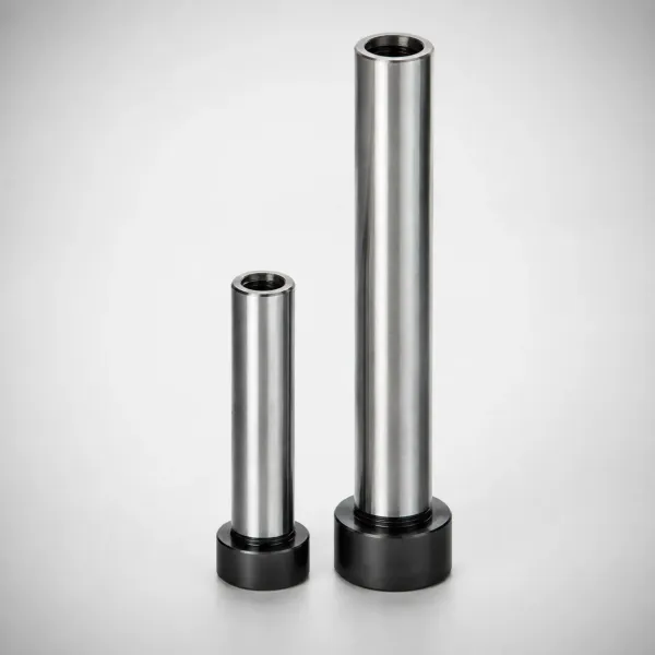
Leader pins and bushings on a die that is reground every 100,000 strokes should be replaced on a separate cycle. A reasonable rule is a bushing replacement every 10 regrinds and a post replacement every 20. That cadence keeps alignment inside 0.01 mm without a full alignment rebuild. Component options and fits are set out on our leader pins and bushings page.
Regrind Intervals by Work Material
Work material sets the regrind interval more than die steel does. The same D2 punch ground to the same edge geometry will run 200,000 strokes in mild steel and 60,000 strokes in 304 stainless. The difference comes from how each material wears the edge.
Mild and galvanized steel. These are the baseline materials. DC01, SPCC and similar low carbon grades support 150,000 to 200,000 strokes per regrind at 0.5 to 1.2 mm thickness. Galvanized stock sits at the low end. The zinc layer smears against the punch land and adds friction, so plan 100,000 to 150,000.
Stainless steel. Grades 304, 316 and 430 work harden at the shear zone. The strip resists fracture, cutting force rises, and the punch edge rounds quickly. Expect 60,000 to 100,000 strokes and 0.08 to 0.10 mm of removal per regrind. A TiCN or DLC coating on the punch adds 30 to 50 percent to that interval. It is often cheaper than grinding twice as often.
Aluminum and copper alloys. Soft metals wear edges by adhesion rather than abrasion. Aluminum builds up on the punch face and drags across the land, so the edge dulls through a transfer layer. Intervals run 80,000 to 120,000 strokes for aluminum and 90,000 to 140,000 for copper and brass. Polishing the punch land to Ra 0.1 µm and running a lubricant matched to the alloy both extend the interval. Adhesion on the die side is a separate failure mode and needs its own inspection routine.
High-strength and advanced steels. Grades at 590 MPa and above cut the interval to 40,000 to 70,000 strokes and drive removal to 0.10 mm per regrind. Electrical steels with silicon content behave differently. They are abrasive on the edge but run at only 0.2 to 0.5 mm thickness. A coated or carbide-tipped punch can hold 200,000 to 300,000 strokes. Material choice for these applications is covered in how to select stamping die steel.
Stroke Life Baseline by Material and Thickness
Use the table below as a planning baseline, then adjust it with your own burr and force data. The intervals assume a properly clearanced die and a punch at HRC 58 to 62. Each pass removes 0.05 mm from the face unless the table notes otherwise.
| Work material | Typical thickness | Strokes per regrind | Removal per regrind |
|---|---|---|---|
| Mild steel DC01 / SPCC | 0.5 to 1.2 mm | 150,000 to 200,000 | 0.05 mm |
| Galvanized steel | 0.6 to 1.5 mm | 100,000 to 150,000 | 0.05 to 0.08 mm |
| Stainless 304 / 316 | 0.5 to 1.5 mm | 60,000 to 100,000 | 0.08 to 0.10 mm |
| Aluminum 5052 / 6061 | 0.8 to 2.0 mm | 80,000 to 120,000 | 0.08 to 0.10 mm |
| Copper and brass | 0.4 to 1.0 mm | 90,000 to 140,000 | 0.05 to 0.08 mm |
| High-strength steel 590 MPa and above | 1.0 to 2.5 mm | 40,000 to 70,000 | 0.10 mm |
| Electrical steel, Si content | 0.2 to 0.5 mm | 200,000 to 300,000 | 0.03 to 0.05 mm |
← swipe to scroll →
Table note: typical industry figures for progressive dies with correct clearance and an HRC 58 to 62 punch edge; thin-stock and coated-punch applications can exceed the upper end.
Thickness scales the interval faster than most shops expect. Going from 1.0 mm to 2.0 mm stock roughly cuts the interval by 40 percent, because load per unit edge length doubles. Two dies running the same material at different thicknesses should be scheduled on separate stroke counts, not one shop-wide number.
Regrind or Replace the Insert: The Cost Test
Regrinding is almost always cheaper per pass, but it is not always the right move. The decision turns on remaining allowance, edge damage depth and the cost of the downtime that either option consumes.
Run the numbers on one station. A regrind pass costs 2 to 4 hours of press time and 150 to 400 dollars of labor and machine time. A new insert costs 600 to 3,000 dollars plus 8 to 14 hours of downtime for fitting, setting and re-timing the station. On a single pass the regrind wins by 4 to 9 times on parts cost alone.
The picture changes as allowance runs out. If only two regrind passes remain, the planned replacement should be pulled forward into a scheduled shutdown instead of waiting for the third pass. The decision rules that work in practice are:
Replace when the remaining allowance is under 0.20 mm. That is less than three passes at 0.05 to 0.10 mm each, so the insert cannot carry the die to its next planned maintenance window.
Replace when edge chipping exceeds 0.30 mm deep. Grinding out a chip that deep removes 0.10 to 0.15 mm of stock. The softened zone from the repair often runs 0.5 mm back from the edge. A repaired punch in that condition typically returns to the grinder 40 to 50 percent sooner than a sound one.
Replace when the wear rate doubles. A punch that used to give 150,000 strokes and now gives 70,000 has a metallurgy problem. Grinding burn is the usual cause. Compare cost per 1,000 strokes rather than cost per event, and the crossover shows up quickly.
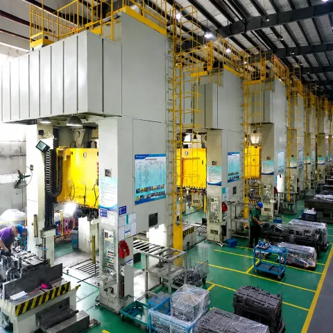
A certified die shop can quantify this for you. DieStrike runs IATF 16949 production and offers stamping die manufacturing with 2 to 5 week lead times on new progressive, compound and blanking tools. That matters when a replacement decision lands on a station that also needs a geometry update.
Tracking Regrinds With a Die History Card
A die history card turns a pile of regrind events into a forecast. The card travels with the tool, and every entry is a number rather than an opinion. Without it, the shop relearns the same die's wear rate every time a new planner takes over.
Log these fields at every regrind. Stroke count at pull, burr height and edge radius before grinding, material removed, punch length after grinding. Then shim thickness added, clearance measured, the press it ran on, and the operator. Ten fields, one line per event.
The wear rate is the payload. Divide material removed by strokes run and you get millimetres per 100,000 strokes. A die that removes 0.05 mm every 100,000 strokes has a stable rate. A die that jumps from 0.05 to 0.10 mm at the same stroke count has a process problem, not a wear problem. Common causes are clearance that has drifted 20 percent above target, a shim that has crushed, or a strip material change that no one recorded.
Use the rate to set the next interval instead of running a fixed calendar. Say the measured rate is 0.05 mm per 100,000 strokes and the shop wants a 0.05 mm pass. The next regrind is due 100,000 strokes after the last one. Add a safety margin of 10 to 20 percent for material lot variation, and the schedule builds itself from real data.
Keep the card with the die, and keep a digital copy against the part number. Traceability auditors for automotive and connector programs expect a maintenance record tied to a stroke count. That record also lets you answer a burr complaint with data instead of a re-run.
Six Regrind Errors That Scrap Dies
1. Grinding without checking clearance. A shop grinds the punch, measures nothing laterally, and runs the die back into production with clearance at 15 percent of stock thickness. Burr height climbs within 20,000 strokes and the next regrind comes early. Measure clearance after every third regrind at minimum.
2. Over-grinding past the allowance. Taking 0.15 mm when 0.05 mm was needed burns 3 passes of allowance in one event. A die with 1.5 mm of allowance and a habit of 0.15 mm passes gets 10 regrinds instead of 30. The insert is scrapped years early.
3. Ignoring height difference between punches. In a multi-punch station, all punches must sit within 0.01 mm of each other. One punch standing 0.03 mm high takes the load, chips, and dumps the burden onto its neighbours. Check height on a surface plate with an indicator after every regrind.
4. Grinding without coolant and burning the edge. A tip that hits 200 °C loses 1 to 2 HRC. The die still cuts, but the next interval drops by 30 to 50 percent and the shop never connects the two events. Flood coolant on every pass.
5. Leaving a razor edge. A perfectly sharp punch edge chips on the first few hits. A 0.005 to 0.010 mm edge break or a 15 to 20 degree chamfer costs one minute. It separates a 150,000 stroke interval from a 40,000 stroke one.
6. Returning the die without updating the record. No shim stack note means the next technician guesses the punch height. No stroke count means the next regrind is scheduled on feel. A die sent back to production without an updated history card is a die that will be reground again, out of schedule, within a month.
Regrind Scheduling FAQ
Q1. How often should a stamping die be reground?
Set the interval by material and thickness, then verify it with measurement. Mild steel at 0.5 to 1.2 mm runs 150,000 to 200,000 strokes. Stainless 304 runs 60,000 to 100,000. High-strength steel at 590 MPa and above runs 40,000 to 70,000. Whichever number is smaller applies: either the stroke count or a measured burr height above 0.05 mm.
Q2. What burr height should trigger a regrind?
0.05 mm is the general trigger for stamping. Connector, terminal and electrical parts often specify 0.03 mm or tighter, so the customer print overrides the shop default. On stock thicker than 2 mm, plan the regrind before burr reaches 0.08 mm. At that thickness burr grows quickly and the strip can jam the feed.
Q3. How much material can be ground off a punch in total?
Most production punches carry 1.0 to 3.0 mm of regrind allowance above the working edge. At 0.05 to 0.10 mm per pass, that is 10 to 30 regrinds. The limit is set by the minimum safe punch length and by the die's shut height, not by the punch material. Record the remaining allowance on the die history card so it is never a surprise.
Q4. Does regrinding change the punch clearance?
Face grinding does not change lateral clearance, because the gap between the punch side and the die opening stays the same. Die opening wear does change it over time. A die button bore can open 0.02 to 0.04 mm over 5 million strokes, which adds directly to clearance. Measure clearance after every third regrind and re-shim or replace the button if drift passes 20 percent of target.
Q5. Can a coated punch be reground, or must it be replaced?
A coated punch can be reground. Grinding removes the TiCN or DLC layer from the face and land, so the punch has to be re-coated after sharpening. Expect to remove 0.005 to 0.010 mm from the substrate when stripping the old coating. Budget a 2 to 4 µm coating thickness on the rebuild. Re-coating costs far less than a new insert. It restores the 30 to 50 percent interval gain that made the coating worth buying.
The Bottom Line
Schedule the regrind on measured burr height, edge radius and cutting force, never on feel. Keep the pass at 0.05 mm, restore the shim stack, re-check clearance every third cycle, and log every event. Do that and a die with 1.5 mm of allowance delivers roughly 4.5 million strokes before the inserts retire. For dies that need that level of control designed in from the start, talk to our tooling engineers.
KEEP READING
Related Reading
How to Maintain Punch Clearance in Progressive Dies
Clearance targets from 5 to 10 percent of stock thickness per side, plus how to read wear on a die button.
Read articleArticleHow to Select Stamping Die Steel
D2, M2, A2 and carbide grades compared by hardness, toughness and edge retention on high-volume stamping.
Read articleArticlePilot Pins vs Guide Posts in Stamping Dies
When a progressive die needs pilot pins instead of guide posts to hold 0.02 mm strip location.
Read articleServiceStamping Die Manufacturing
Progressive, compound and blanking dies built to IATF 16949 with 2 to 5 week lead times.
Read articleNEXT STEP
Ready to Start Your Mold?
Send us your element dimensions or part numbers — our team responds within 24 hours with pricing and lead time.

Written by
Ray ChanMold Buyer's Guide Author · Precision Mold Manufacturing Specialist. Ray helps global importers, distributors and OEMs source factory-direct molds and mold parts.