
Pilot Pins vs Guide Posts in Progressive Dies: How to Use Each
Table of Contents
A 12-station progressive die runs at 350 strokes per minute in a 400-ton press. Midway through a 200,000-hit order, hole positions on the finished bracket drift 0.15 mm out of a ±0.10 mm tolerance band. The pressroom swaps material lots, rechecks the feed length and still sees drift. The real cause sits on two components that maintenance treats as interchangeable. A worn pilot pin lets the strip shift by the full feed error every stroke. A scored guide post lets the upper die lean, opening punch-to-die clearance on one side. These two failures look identical on the part, and they need opposite fixes.
Confusing the two roles is a common and expensive mistake. Guide posts do not locate your strip. Pilot pins do not square your die halves. A die that relies on guide posts for part accuracy will scrap material at a rate that climbs with every stroke. This article separates the two functions, gives you typical numbers for diameter, clearance, hardness and speed limits, and shows you how to inspect both systems before the drift reaches your parts.
The Snapshot
- Pilot pins correct strip position to ±0.02-0.05 mm (typical). Roller feeds alone repeat feed length to about ±0.05-0.10 mm, so pilots close the remaining error.
- Guide posts align the upper die shoe to the lower die shoe, typically holding ±0.01-0.05 mm lateral register (industry figures, precision ball guide sets at the tight end).
- Pilot pin clearance runs 0.025-0.05 mm per side (typical), which means 0.05-0.10 mm on diameter against the pilot hole.
- Ball bearing guide post sets suit continuous running above 1000 SPM. Sliding (plain bushing) sets are the standard choice up to roughly 300-500 SPM (typical).
- DieStrike builds stamping dies in 2-5 weeks and ships standard components including punches, guide posts and springs in 3-7 days.
What a Pilot Pin Does: Strip Locating and Pitch Correction
A pilot pin is a hardened, precision-ground pin that enters a previously pierced hole in the strip just before the forming or cutting station closes. Its single job is workpiece registration. It pulls the strip into exact lateral and pitch position so every downstream feature lands where the drawing says it should.
The need comes from the feed system. A servo roller feed repeats feed length to about ±0.05-0.10 mm under normal conditions (typical). Lubricant film, coil set, material thickness variation and stop-start dynamics all add error. That residual error is fine for blanking a washer. It is not fine for a connector terminal with a ±0.05 mm hole position tolerance.
The pilot closes that gap. When the pin enters the pilot hole, its lead-in section contacts the hole edge and shifts the strip until the pin is centered. At full penetration the strip sits within ±0.02-0.05 mm of true position (typical for a properly designed pilot system). Every cutting station after the pilot then works from a registered strip, not from the feed's best guess.
Two mounting styles. A direct pilot is ground onto the punch itself or inserted into the punch, so piercing and locating happen with one component. An indirect pilot is a separate pin mounted in the upper die or stripper plate, entering a hole pierced one or two stations earlier. Indirect pilots are the default for high-precision progressive work because they can be made larger, harder and easier to replace than a piloted punch tip.
Where pilots go in the station layout. Place the pilot entry one station before the critical forming or cutting action, never in the same station as the cut it protects unless the pilot is part of the punch. The strip must be clamped by the stripper or pressure pads while the pilot enters, or the strip lifts and the pilot bends. In our guide to how to build a progressive die we walk through station sequencing in full, including pilot placement rules for 8 to 20 station layouts.
What Guide Posts Do: Upper-to-Lower Die Alignment
Guide posts, also called leader pins, are the columns mounted in the lower die shoe that travel with bushings in the upper die shoe. Their job is die-to-die alignment. Every stroke, they force the upper half of the die to close in the same lateral position relative to the lower half, within the precision of the post-and-bushing pair.
A standard four-post die set holds lateral alignment to roughly ±0.02-0.05 mm (typical). A precision ball bearing guide set can hold ±0.01 mm or better (industry figures). That number matters because punch-to-die clearance is tiny. A 1 mm thick mild steel strip often runs 10 percent of thickness per side, about 0.10 mm. If the upper die shifts 0.10 mm laterally, clearance doubles on one side and drops to zero on the other. The punch chips, the die galls and burrs grow on every part.
Guide posts carry no part-location duty. They align steel to steel. The strip floats between them, held only by feed fingers, pilots and pressure pads. A die with new guide posts and worn pilots still produces out-of-tolerance hole patterns, because nothing corrects strip pitch error. Conversely, perfect pilots cannot save a die whose posts are worn, because every punch enters its die at an angle.
Post count and placement. Simple single-hit blanking dies may run two posts. Progressive dies standard on four, one near each corner of the shoe. High-precision dies for connector terminals and fine-pitch parts often add a fifth post or use larger diameter posts near the high-load stations. Asymmetrical post patterns, with one oversized post, prevent the die from closing backwards during setup. That error kills pilots and punches in a single stroke.
Pilot Pins vs Guide Posts: Side-by-Side Comparison
The two systems work together but never substitute for each other. The table below separates them by function, precision, mounting and failure signature. Keep it as a quick reference during die review and troubleshooting.
| Attribute | Pilot Pin | Guide Post |
|---|---|---|
| Primary function | Locates the strip, corrects pitch and lateral feed error | Aligns upper die shoe to lower die shoe every stroke |
| What it registers | Workpiece to die | Die half to die half |
| Typical precision held | ±0.02-0.05 mm strip position | ±0.01-0.05 mm lateral alignment |
| Mounting location | Punch, punch holder or stripper plate, above the strip | Lower die shoe, full die height, with bushings in upper shoe |
| Engagement timing | Enters pilot hole before cutting stations close | Engaged through the entire stroke, first contact at die close |
| Typical clearance | 0.025-0.05 mm per side on pilot hole | 0.005-0.015 mm post-to-bushing (sliding sets, typical) |
| Common failure | Breakage or wear, causing hole position drift | Galling or wear, causing uneven punch clearance and chipping |
| Interchangeable? | No. Cannot align die halves | No. Cannot correct strip pitch error |
← swipe to scroll →
Table note: Precision and clearance values are typical industry figures for progressive stamping dies up to 3 mm material thickness. Actual values depend on die grade, press condition and part tolerance.
Read the failure signature, not the guess. Hole positions drifting over hours points at pilots. Burrs growing on one side of the part, with chipped punch edges, points at guide posts. When both defects appear together, check guide posts first. A leaning upper die loads the pilots sideways, and the pilots then break or wear out at several times their normal rate.
Pilot Pin Geometry: Diameter, Clearance, Length and Lead-In
Pilot pin design is arithmetic, not art. Four dimensions decide whether the pin registers the strip or destroys the pilot hole. Get any one wrong and the tolerance advantage disappears.
Diameter. Size the pilot to the pierced hole it enters. General practice keeps the pilot diameter at least 60 percent of material thickness, and larger whenever the strip layout allows. A 1.5 mm thick high-strength steel strip wants a pilot of 3 mm or more in diameter. Thin pilots bend under side load, and a bent pilot registers nothing.
Clearance. The fit between pilot and hole runs 0.025-0.05 mm per side (typical), which is 0.05-0.10 mm on diameter. Too tight and the pin galls the hole edge, dragging material and tearing the strip surface. Too loose and the strip slops inside the clearance band, so your ±0.02 mm registration claim becomes ±0.05 mm in practice. High-strength steels and thicker strips sit at the looser end of the range. Fine-pitch connector terminals in soft copper alloys sit at the tight end.
Pilot length and penetration. The straight section should penetrate the full material thickness plus 1-2 mm before the cutting station closes, with the lead-in section fully clear of the hole. Full penetration matters. If the pin only enters half the strip thickness when the punch starts cutting, the strip can still shift under cutting load and the pilot did nothing.
Lead-in angle. Grind a lead-in of 10-15 degrees per side, or a radius entry, over a length of 1-1.5 times material thickness (typical). The lead-in converts feed error into a smooth centering action. Without it, the pin edge strikes the hole wall square on and either deforms the hole or snaps the pin. Some shops use a two-stage entry, a long 30-degree approach for gross correction followed by the final straight section, on dies with sloppy coil feeding.

One pilot or two. A single pilot corrects pitch, the along-strip direction, but not lateral camber. Precision dies use two pilots spaced across the strip width, or one round pilot plus one shaped pilot that controls rotation. When the part has features on both sides of the carrier, two pilots are the standard minimum. Connector OEMs including TE Connectivity, Amphenol and Luxshare run multi-pilot layouts as a rule because their hole patterns carry ±0.05 mm position tolerance or tighter.
Ball Bearing vs Sliding Guide Posts: Choosing by Speed
Guide post sets come in two constructions, and the choice follows press speed first, budget second.
Sliding (plain bushing) sets. A hardened steel post runs inside a bronze or composite bushing with a thin oil film. They are the workhorse up to roughly 300-500 SPM (typical), cost less per set and tolerate contamination better. The film needs oil. A dry sliding set galls within hours, and galling is irreversible scoring you can feel with a fingernail.
Ball bearing sets. Hardened posts run in a ball retainer cage, often preloaded so there is zero clearance between post, balls and bushing. Friction drops by an order of magnitude versus sliding contact, heat stays low and the set stays precise at 1000 SPM and beyond. High-speed terminals, laminations and small motor punches run on ball sets as a rule. The tradeoff is cost, roughly 2-4 times a comparable sliding set (typical), and sensitivity to shock loads and dirt, which dent raceways permanently.
| Attribute | Sliding Guide Set | Ball Bearing Guide Set |
|---|---|---|
| Typical speed limit | Up to 300-500 SPM | 1000+ SPM continuous |
| Post-to-bushing clearance | 0.005-0.015 mm typical | Preloaded, near zero |
| Friction and heat | Higher, needs continuous lubrication | Low, runs cooler at speed |
| Relative cost | 1x baseline | 2-4x baseline (typical) |
| Contamination tolerance | Tolerant, bronze forgives grit | Sensitive, grit brinells races |
| Wear signature | Bushing bore opens up, play grows | Retainer fails first, then races dent |
| Best applications | General progressive dies, forms, heavy blanks | High-speed terminals, laminations, micro punches |
← swipe to scroll →
Table note: Speed limits and cost multiples are typical industry figures. Follow the die set manufacturer's rated speed for the specific post diameter and stroke length.
Sizing rule. Post diameter scales with die shoe size and cutting force. Common practice puts 25-32 mm posts on dies up to about 400 x 500 mm shoe area, and 38-50 mm posts above that (typical). Long strokes and off-center cutting loads push you one size up. Side thrust from cam actions is the usual reason a guide set wears out early, and side locks or wear plates should carry cam loads instead of the posts.
Installing Guide Posts: Fits, Preload and Parallelism
A guide set is only as good as its installation. The posts and bushings are ground to tolerances in the microns, and sloppy mounting throws that precision away before the first stroke.
Mounting fits. Standard practice presses posts into the lower shoe with a light interference fit, H7/p6 or equivalent (typical), and locates them with a shoulder or retaining ring. Bushings in the upper shoe run H7/k6 or H7/j6 so they stay put but can be pressed out for replacement. Never install posts by hammer blows to the head. A bruised raceway or bent post shows up as alignment drift nobody can diagnose.
Squareness and parallelism. Each post must be perpendicular to the die shoe within about 0.01-0.02 mm over its working length (typical). Install with the shoes on a surface plate, indicate each post, and shim or regrind as needed. A post out of square by 0.05 mm forces the upper die to tilt as it closes, and that tilt loads every punch at an angle. This is one of the quiet causes of one-sided burr that die maintenance chases for months.
Working length and die height. The post must stay inside the bushing at the top of the stroke. If the bushing uncovers the post tip, or the post bottoms on the shoe, you get impact loading and immediate damage. Check the shut height calculation against the guide set's engagement length before you ever set the die in the press. Precision dies for thin materials often run short-stroke, large-diameter ball sets for exactly this reason.

Wear Checks for Pilot Pins and Guide Posts
Both systems wear invisibly until parts go out of tolerance. A scheduled check routine catches them while they are still in the correctable window. Here is what to measure and how often.
Pilot pin checks, every die pull. Measure pin diameter at the straight section with a micrometer. Replace at 0.01 mm of wear on diameter, or sooner if the pin's clearance budget was already at the tight end. Look for galling, a dull grey smeared surface, and for edge chipping at the lead-in transition. Check the pilot holes in the strip too. A hole with a deformed, egg-shaped edge means the pin is bending or the lead-in is damaged, and the pin is not the only casualty.
Guide post checks, weekly on production dies. With the die open at mid-stroke, try to rock the upper shoe laterally by hand. Any perceptible play on a sliding set means the bushing bore has opened. Ball sets should show zero perceptible play, and any movement at all condemns the retainer or races. Then look at surfaces. Sliding posts should be mirror-bright. Bronze transfer, grey streaks or fingernail-catching grooves mean lubrication failed and the set is galling.
Quantify the drift. The cheap way to catch alignment loss before scrap loss is a witness-part routine. Every shift, or every 5,000 hits, pull one part and check hole positions with a CMM or optical comparator against the first-article report. Log the trend. A hole position drifting steadily in one direction is pilot wear or feed drift. A scatter pattern that grows in all directions is guide play. This is the same discipline we describe in how to maintain punch clearance in progressive dies, because guide wear and clearance loss are the same failure seen from two ends.
Lubrication is a wear check. Sliding guide sets need oil fed to the bushing grooves continuously, typically a few drops per minute per post through an automatic lubricator (typical). If the oil reservoir drops slower than planned, a line is blocked and a post is running dry right now. Ball sets need grease packed at intervals defined by the manufacturer, often every 500-1,000 production hours (typical), and never mixed grease types in one retainer.
Failure Modes: Broken Pilots and Galled Guide Posts
Each system fails in its own way, and each failure writes a distinct signature on your parts. Learn the signatures and diagnosis takes minutes instead of days.
Pilot pin breakage. The classic cause is feed misalignment. If the strip arrives with pitch error beyond the lead-in's correction capability, the pin hits solid material instead of a hole and snaps, usually at the lead-in transition where bending stress concentrates. Other causes are undersized pin diameter for the side load, missing stripper pressure that lets the strip lift, and a damaged pilot hole from a dull pierce punch. When a pilot breaks mid-run and the press does not stop, every downstream station cuts from an unregistered strip. Expect hole position errors of 0.10-0.30 mm on the parts stamped after breakage, well outside the ±0.02-0.05 mm the pilot system was built to hold. Quarantine all parts back to the last good witness check.
Pilot wear. Wear shows as gradual one-directional drift in hole position, the same direction every time, because the strip settles against the worn side of the pin. At 0.01 mm of diameter loss, a pin designed for 0.025 mm per side clearance is now at 0.035 mm per side, and registration accuracy degrades by roughly that amount. Replace before the drift reaches part tolerance.
Guide post galling. Galling is adhesive wear from a collapsed lubricant film. It starts as bronze or steel transfer streaks and grows into longitudinal grooves. Once grooved, the post-to-bushing fit opens from 0.005-0.015 mm toward 0.05 mm and beyond. The upper die now wanders under cutting load, punch-to-die clearance varies station to station, and you see burrs growing unevenly across the strip width plus early punch chipping. Galled posts cannot be saved by polishing if grooves are deep. Replace the set in matched pairs, post and bushing together.
Retainer failure on ball sets. Ball retainers crack from shock loading, usually a die crash or a mis-set shut height. A broken cage dumps balls into the raceway and scores it within strokes. If you hear a change in the die's closing sound after a crash, pull the die and inspect the guide set before continuing, even if parts still look acceptable.

Materials and Hardness for Pilots and Guide Posts
Both components live on hardness and surface finish, but they are made from different families of steel because their loads differ.
Pilot pins. Standard choices are tool steels like SKD11 (D2 class), ground and hardened to HRC 58-62 (typical). For high-volume dies running abrasive high-strength steels, powder metallurgy grades or tungsten carbide pilots push life from hundreds of thousands of hits into the tens of millions (industry figures). Carbide is brittle, so reserve it for well-aligned dies with rigid strippers. Surface finish on the pilot's working sections should be Ra 0.2-0.4 µm or better (typical), because a rough pin galls the hole edge no matter how good the clearance math is. Our companion piece on stamping die steel selection covers when to move from SKD11 to powder steel or carbide for die components in general.
Guide posts. Posts are typically case-hardened alloy steels or through-hardened bearing steels such as SUJ2 (52100 class), reaching HRC 58-64 on the working surface (typical), ground to Ra 0.2 µm or finer. Bushings for sliding sets use oil-impregnated bronze or aluminum bronze for heavy loads. Ball sets use hardened steel races with SUJ2 balls. The hardness pairing matters. A post softer than its bushing wears fast, and a set with identical hardness on both sliding surfaces tends to gall. Standard sets keep a hardness differential of at least a few HRC points between mating parts.
Corrosion is a wear accelerator. In humid pressrooms, an unlubricated sliding set can develop surface rust between shifts. Rust pits become stress risers and grit. A die going into storage needs its posts greased and wrapped. This is the stamping equivalent of the mold storage discipline we cover for tooling that sits idle between campaigns.
Design Checklist: Using Each Component Correctly
Run this checklist at die design review. Each line encodes a mistake that shows up in production as scrap.
- Pilot diameter at least 60 percent of material thickness, and pilot-to-hole clearance set at 0.025-0.05 mm per side (typical) based on strip material.
- Pilot straight section penetrates full material thickness plus 1-2 mm before any protected cutting station closes.
- Lead-in of 10-15 degrees per side or radius entry, ground to Ra 0.2-0.4 µm, with no sharp transition at the lead-in shoulder.
- Two pilots, or one round plus one shaped, whenever the part has features on both sides of the strip or rotation control is needed.
- Strip clamped by stripper or pressure pads during pilot entry, with pilot entry timed one station ahead of critical cuts.
- Four guide posts minimum on progressive dies, with an asymmetrical pattern or one oversized post to prevent backwards die closing.
- Ball bearing guide set selected when continuous speed exceeds 1000 SPM, sliding set acceptable up to 300-500 SPM (typical).
- Post perpendicularity held to 0.01-0.02 mm over working length at installation, verified on a surface plate.
- Post engagement maintained across the full stroke, no tip exposure and no bottoming at shut height.
- Cam and side-thrust loads carried by side locks or wear plates, never by the guide set.
- Automatic lubrication plumbed to every sliding bushing, with reservoir consumption checked per shift.
- Witness part measured every shift or every 5,000 hits, with hole position trended against first article.
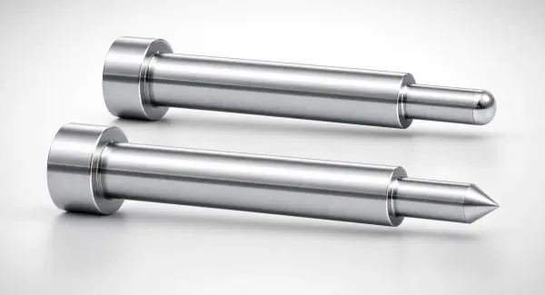
Where pilots matter most. Connector terminals, leadframes, laminations and any part with multi-row hole patterns are pilot-critical by definition. Fine-pitch work with ±0.03 mm position tolerance has no other way to register the strip. If your part tolerances are looser than ±0.15 mm and the feed is a modern servo unit, you may run pilot-free, but only after a capability study proves the feed repeats within tolerance over a full coil, including the coil's head and tail where feed dynamics change.
Sourcing: Lead Times and Standard Parts
Both components split cleanly into standard catalog items and made-to-print specials, and the two paths have very different clocks.
Standard components move fast. Catalog guide post sets, standard pilot pins, punches, springs, die sets and mold bases are commodity items stocked by precision tooling makers. At DieStrike, standard components ship in 3-7 days, which means a galled guide set or a broken pilot should cost you a single shift of downtime, not a week. Keep matched spare sets on the shelf for every production die. A spare guide set costs a fraction of one day of press idle time.
Special pilots follow die lead time. Pilots with shaped profiles, carbide bodies or stepped designs tied to a specific strip layout are made to print, usually alongside the punches and die sections they serve. A complete progressive die, including its pilot system, runs 2-5 weeks at DieStrike, with DFM feedback on your strip layout and tolerance stack within 24 hours of quote. That DFM window is where pilot sizing gets verified, before the hole pattern is locked and the pierce punches are cut.
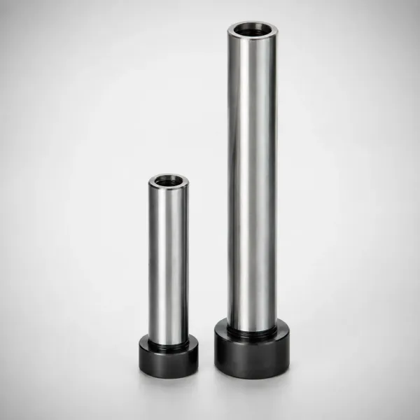
Buy spares against the wear curve, not the break. Pilot pins are consumables. Budget replacements based on measured wear per million hits during die validation, not on hope. Guide sets are semi-permanent but should be replaced in matched post-and-bushing pairs, never mixed across sets, because posts and bushings wear together and a mixed pair runs at the wrong clearance.
FAQ: Pilot Pins and Guide Posts
Q1. Can guide posts replace pilot pins for part accuracy?
No. Guide posts align the upper die shoe to the lower shoe, typically holding ±0.01-0.05 mm of lateral register. They never touch the strip. Feed error of ±0.05-0.10 mm passes straight through to your hole pattern unless a pilot pin corrects it. Precision dies need both systems.
Q2. What clearance should a pilot pin have in the pilot hole?
Typical clearance is 0.025-0.05 mm per side, or 0.05-0.10 mm on diameter. Use the tight end for soft copper alloys and fine-pitch terminals, the loose end for high-strength steels and thicker strips. Below 0.025 mm per side the pin galls the hole edge. Above 0.05 mm you lose the registration benefit.
Q3. When should I specify ball bearing guide posts instead of sliding ones?
Specify ball sets for continuous running above 1000 SPM, for preloaded near-zero clearance, or for dies with carbide inserts where punch-to-die clearance is held under 0.05 mm per side. Sliding sets are fine up to 300-500 SPM and cost roughly one quarter to one half as much (typical). Our comparison of ball-lock punches vs shoulder punches covers a similar speed-versus-cost tradeoff on the punch side.
Q4. How often should I check pilot pins and guide posts for wear?
Check pilot pin diameter at every die pull and replace at 0.01 mm of wear on diameter. Rock-test guide posts weekly on production dies and inspect surfaces for bronze transfer or grooves. Measure one witness part every shift or every 5,000 hits and trend hole positions against the first-article report.
Q5. What happens to parts when a pilot pin breaks mid-run?
Every downstream station cuts from an unregistered strip. Hole positions typically go out by 0.10-0.30 mm, far beyond the ±0.02-0.05 mm the pilot was holding. Quarantine all parts back to the last good witness check, not just the parts after the break you noticed.

The Bottom Line
Pilot pins register the strip to ±0.02-0.05 mm. Guide posts square the die halves to ±0.01-0.05 mm. Neither substitutes for the other, and worn versions of both show up as the same out-of-tolerance parts. Size them right, check them on schedule, and stock spares. DieStrike builds stamping dies to ±0.005 mm in 2-5 weeks and ships standard components in 3-7 days. If you need a pilot system reviewed before your next progressive die build, send us the strip layout through our contact page.
KEEP READING
Related Reading
Fine Blanking vs Conventional Stamping
Fine blanking holds ±0.01 mm edges with triple action. Compare it with conventional progressive stamping before you commit.
Read articleArticleNitrogen Gas Springs vs Coil Springs
Gas springs deliver flat force curves over long strokes. See when they beat coil springs in stripper and pressure systems.
Read articleArticleHow to Select Stamping Die Steel
Match D2, SKD11 and powder metallurgy steels to your strip material, tonnage and expected hit counts.
Read articleServiceStamping Die Manufacturing
Progressive dies built to ±0.005 mm with 2-5 week lead times at our IATF 16949 certified toolroom.
Read articleNEXT STEP
Ready to Start Your Mold?
Send us your element dimensions or part numbers — our team responds within 24 hours with pricing and lead time.

Written by
Ray ChanMold Buyer's Guide Author · Precision Mold Manufacturing Specialist. Ray helps global importers, distributors and OEMs source factory-direct molds and mold parts.