
How to Build a Progressive Die (Step by Step): 8 Steps
Table of Contents
A progressive die for an automotive bracket reached tryout with a 0.12 mm burr on every pierced hole. The first punch chipped at hit 3,400. The strip layout had skipped the pilot station, and cutting clearance was ground at 3% of stock thickness per side. Rework and re-tempering ran $11,000 and pushed delivery out 9 days. That failure was avoidable. This guide walks the 8 build steps with the numbers that keep each one from becoming a rework line item.
Progressive dies combine 5 to 15 stations in one die set. Each stroke of the press moves the strip forward one pitch and completes the part. That is where the economy comes from, and where the risk lives. One station built wrong poisons every part that follows it. A build sequence with checkpoints catches the error before it becomes scrap.
The Snapshot
- Eight build steps: part analysis, strip layout, station design, steel selection, clearance, stripper and springs, machining, assembly, and tryout.
- Cutting clearance runs 5-10% of stock thickness per side for cold rolled steel (industry figures).
- Punch force equals shear strength x shear perimeter x thickness. Stripping force adds 10-20% on top.
- D2 punch and die inserts run HRC 58-62. Carbide takes over past 1 million hits.
- DieStrike builds stamping dies in 2-5 weeks with part geometry at ±0.002 mm under IATF 16949.
The Build Sequence at a Glance
The sequence below is the order that works in a real toolroom. Design steps come first because they lock the geometry. Procurement runs in parallel where possible. Machining is the long pole, so steel ordering happens the day the layout is approved, not the day the design is finished.
| Step | Main Work | Typical Duration |
|---|---|---|
| 1. Part analysis and strip layout | Material, thickness, tolerances, coil width, pitch, nesting | 2-4 days |
| 2. Station design | Operation order, pilot stations, force budget per station | 3-6 days |
| 3. Steel selection and ordering | Die set, punch and die material, heat treat spec | 3-7 days, parallel |
| 4. Cutting clearance and geometry | Clearance per station, die roll allowance, burr budget | Part of design |
| 5. Stripper, springs, guidance | Spring preload, guide pillars, stripper travel | 2-4 days |
| 6. Machining and grinding | Wire EDM, jig grinding, heat treat, coatings | 7-14 days |
| 7. Assembly and press setup | Fit, alignment, shut height, tonnage check | 3-5 days |
| 8. Tryout and sign-off | Samples, burr check, CMM report, documentation | 2-4 days |
← swipe to scroll →
Table: typical toolroom durations for a 5-15 station progressive die; DieStrike stamping die lead time is 2-5 weeks including all 8 steps.
Step 1: Part Analysis and Strip Layout
Every progressive die starts with a part file and a material decision. You need the grade, the thickness, the tensile and shear strength, the grain direction, and the print tolerances before any geometry is drawn. A 1.0 mm cold rolled steel part with a shear strength of 320 MPa behaves differently from a 2.5 mm stainless part at 480 MPa. The numbers drive punch force, clearance, and steel choice later.
Nesting and Material Utilization
Strip layout decides coil width, pitch, feeding direction, and nesting angle. A good layout hits 55-70% material utilization for a typical bracket or connector part. A rushed layout drops below 40%. At $1,100 per ton, a 25% utilization gap on a 0.8 mm strip wastes thousands per 100,000 parts (industry figures).

Feeding direction must follow the part's dominant bend or grain requirement. Holes should sit at least 1.5 times the material thickness from a bend line, or they distort. Adjacent cut features need a scrap bridge of 1.5-2 times the thickness so the strip does not tear between stations. Pilot holes go in the scrap area, never in the part outline, and the first station pierces them.
Tolerance review belongs in this step. A hole positioned at ±0.05 mm is a normal stamping callout. A hole at ±0.01 mm needs a secondary operation or a restrike station, and that changes the layout. DieStrike checks the tolerance stack against the press and the material before the strip layout is locked.
A DFM review at this point is cheap. DieStrike returns DFM feedback within 24 hours and a cost breakdown within 48 hours. The review checks bend radii, hole-to-edge distances, and tolerance feasibility before steel is ordered. A bend radius below 1 times the thickness on a hard grade will crack in forming. That fact is visible in the part file long before it shows up as a failed tryout.
Step 2: Station Design and Pitch
The station sequence is the skeleton of the die. A typical order is: pilot pierce, trim or cut-off, pierce, form, bend, lance, emboss, and final blank. Each station performs one operation, and the strip moves one pitch per stroke. Pitch equals feed length, and pitch error is the fastest way to misalignment between stations.
Force Budget
Punch force follows one formula: F = shear strength x shear perimeter x thickness. Take a rectangular hole with a 120 mm perimeter in 1.2 mm CRS at 320 MPa. Force is 320 x 120 x 1.2, which is 46 kN, or about 4.7 metric tons, for that single station. Add stripping force at 10-20% of the cutting force, then sum every station, then add a 20% margin for press selection.

Pilots are not optional hardware. They locate the strip within ±0.005 mm class tolerance before every critical cut. A pilot hole diameter should be 1.5-2 mm minimum, and the pilot shank should fit the hole with 0.01-0.02 mm clearance. Without pilots, cumulative feed error grows across stations, and the last station cuts parts that do not match the first.
Balance the die so the total force center sits on the press ram center. An offset of 5% of the die width creates tipping, uneven shut height, and premature guide wear. Standard practice is to lay out the strip so heavy cutting stations sit near the center of the die set.
Step 3: Die Steel and Punch Material Selection
Material choice sets the life and the regrind interval of the tool. The rule of thumb is simple: harder steel for longer runs, tougher steel for shock and chipping resistance. D2 is the default for blanking and piercing in steel up to 3 mm. DC53 and M2 handle higher speeds and thinner sections. Carbide is a production machine, not a prototype material.
| Material | Hardness | Best For | Typical Life Between Regrinds |
|---|---|---|---|
| D2 | HRC 58-62 | General blanking and piercing, 0.5-3 mm steel | 100k-500k hits |
| DC53 | HRC 60-62 | Thin sections, high-speed blanking | 300k-800k hits |
| M2 HSS | HRC 62-65 | Punches, edge retention | 200k-600k hits |
| Tungsten carbide | HRA 88-92 | High volume, abrasive stock, high SPM | 1M+ hits |
← swipe to scroll →
Table: industry figures for tool steels and carbide; life depends on stock, lubrication, and clearance.
Die buttons replace a full hardened die block in multi-station dies. Each button is a replaceable insert, so one worn station does not scrap the die set. Punches come as shoulder punches or ball-lock punches, and standard diameters follow DME, MISUMI, or Dayton progress series. A standard 6 mm punch with a 3-7 day ship time beats a special grind that takes 3 weeks.
DieStrike hardens cavity and die steels to HRC 62 and holds mold part geometry at ±0.002 mm. Standard components including punches, springs, and leader pins ship in 3-7 days. That combination keeps the long pole of the schedule on the custom machining, not on waiting for stock. For a full stamping die manufacturing review, the same engineering team runs the layout, the build, and the tryout.
Step 4: Cutting Clearance and Die Roll
Cutting clearance is the gap between punch and die button, measured per side. It is the single most copied number in progressive die building, and the most commonly wrong one. For cold rolled steel the working range is 5-10% of stock thickness per side. A 1.0 mm CRS part gets 0.05-0.10 mm per side. Stainless runs 10-15%. Aluminum runs 3-5%. These are industry figures, and they hold across most automotive and appliance grades.
What Wrong Clearance Does
Clearance too small raises cutting force, hammers the punch edge, and produces a heavy burr with a bright burnished band. Clearance too large increases die roll, leaves a heavy burr on the opposite edge, and distorts the part around the cut. Both show up as scrap before the first 1,000 hits if the strip is checked properly.

Die roll is the rounded edge on the blank side of the cut. It runs 10-15% of stock thickness and is invisible on most parts, but cosmetic edges and tight dimensions see it immediately. If the print calls a pierced hole dimension from the die-roll side, the layout must move the burr side to the inside of the tolerance.
Burr height is the field acceptance test. The practical limit is 0.05-0.1 mm, or about 10% of thickness, whichever is smaller, on a 1.0 mm part. A burr gauge and a 10x loupe catch it in 30 seconds at tryout. When burr exceeds the limit, check clearance first, then punch sharpness, then alignment.
Step 5: Stripper, Springs, and Guidance
The stripper holds the strip flat during cutting and pulls the punch out of the material on the return stroke. A fixed stripper is simple and cheap. A spring-loaded stripper clamps the strip before the punch touches it, which controls die roll and flatness. For precision blanks and formed features, spring-loaded is the standard answer.
Springs and Stripping Force
Stripping force runs 10-20% of the cutting force for flat punches. A 46 kN station needs 4.6-9.2 kN of stripping force. Coil springs follow ISO 10243 color codes: yellow, blue, red, and green indicate increasing load capacity. Preload should be 10-30% of the spring stroke, and total travel must exceed the punch penetration depth plus 1-2 mm of clearance.
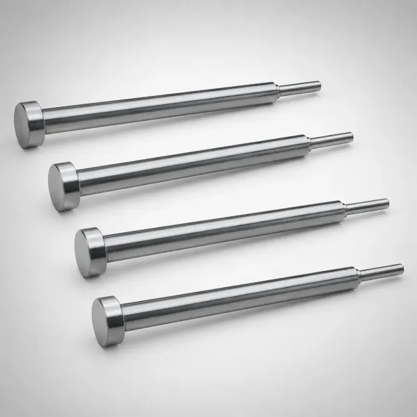
Guidance keeps punch and die button concentric at every stroke. A four-pillar die set with ball-cage guide pillars and bushings holds alignment in the 0.005-0.01 mm range. Standard leader pin and bushing pairs from DME or MISUMI series are ground to matched fit classes. Punch plate bores must sit within ±0.005 mm of the die button bores.
Stripper travel and spring pockets are drawn at this step, not left to the machinist. The pockets need depth for the spring, 10-30% preload, and travel. The stripper guide rides on the pillars at a 0.01-0.02 mm sliding fit. These dimensions are cheap on paper and expensive to cut twice in hardened steel.
Step 6: Machining and Grinding the Tool
Machining starts the day the steel arrives. The sequence matters as much as the tolerances: machine soft, stress relieve, harden, then finish grind and wire cut. Cutting a profile into hardened steel with wire EDM beats cutting it soft and hoping heat treat does not move it. D2 air hardens around 980-1040°C and stabilizes near HRC 60-62 after double tempering (typical industry figures).
Wire EDM and Jig Grinding
Wire EDM cuts punch and die profiles to ±0.002-0.005 mm with a surface finish of Ra 0.4-0.8 µm. Round punches get jig ground to ±0.002 mm on the diameter. At DieStrike the same tolerance discipline applies across mold and die work: part geometry at ±0.002 mm, verified on CMM after finishing.

Surface coating is a life decision, not decoration. TiN and CrN coatings at 2-4 µm thickness cut galling and double punch life on abrasive stock. A coated punch runs 200k-600k hits between regrinds where an uncoated punch in the same station may stop at 100k (industry figures). The coating goes on after final grinding so the land dimension stays true.
Wire EDM also cuts the stripper profile and the pilot holes in one setup. Using the same machine and program for mating parts keeps the station pattern consistent. Skim cuts at 0.02-0.05 mm per pass improve the edge finish on the final land.
Cooling holes, dowel pin locations, and mounting bores are machined in the soft state. Dowel holes are reamed to H7 fit, and the punch plate and die shoe are doweled together before hardening to lock the station pattern. That single step prevents the classic mismatch where every station is perfect and nothing lines up.
Step 7: Assembly, Shut Height, and Press Setup
Assembly is where the die becomes a machine. Punches are pressed into the punch plate, die buttons into the die shoe, and the stripper rides on the pillars. Alignment is checked with feeler gauges and a test pin through each punch-die pair. A 0.01 mm step between punch and die button shows in the first 100 parts. It is checked before the die goes near a press.
Shut Height and Press Selection
Shut height is the closed height of the die, and it must sit inside the press's adjustment window. Die height adjustment is typically 5-10 mm of the press stroke. Press tonnage is the sum of all station forces plus stripping plus a 20% safety margin. A die that sums to 40 metric tons needs a 50 ton press, and the ram speed should match the station design, commonly 100-600 SPM.

Feeding is part of press setup. The coil feeder must advance exactly one pitch per stroke, with pitch accuracy at ±0.05 mm for a die running pilots. The strip should enter the die flat and leave it flat, with the scrap skeleton exiting without drag. Feeder roll pressure too high marks the strip; too low lets it slip and strips the pilots.
Lubrication is a setup item, not an afterthought. Stamp oil applied to both strip faces at 2-5 g/m² is typical for CRS. The lubricant does three jobs: cool the cutting edge, flush fines, and prevent galling. A dry strip is the fastest way to turn a good die into a regrind schedule.
Step 8: Tryout and Dimensional Sign-Off
Tryout is the verification gate. The die runs 500-1,000 hits to stabilize the edges and prove the strip feeds. Every station is checked for burr, die roll, and dimension against the print. A CMM report covers the critical dimensions, typically 5-15 features for a bracket, and the first article is kept as the master sample.
Structure the tryout in two milestones. T0 proves function: feed, strip, eject, and cycle at speed. T1 proves dimensions: the CMM pass, burr survey, and surface check. Correcting a function problem after a dimensional pass wastes both passes, so the order is fixed. A written defect log at each milestone separates a professional toolroom from a shoot-and-hope operation.
The sample count matters. A 50-hit sample hides a burr trend that a 500-hit run exposes. Run length should cover at least one full coil join. Coil-to-coil thickness variation of 0.01-0.03 mm changes clearance behavior at the thin end of the tolerance band.
Edge quality is measured on the first samples and again at hit 500. Burr must stay under 0.05-0.1 mm, and punch edge condition is checked with a loupe for micro-chipping. If chipping appears inside the first 1,000 hits, the cause is usually clearance, alignment, or a sharp punch corner. The material is rarely the fault.
Delivery includes more than the die. DieStrike ships the CMM report, steel certificates, trial samples, and a maintenance sheet that lists regrind intervals and spare part numbers. The die leaves the shop as a documented asset, not a box of steel. That documentation is what makes the second 100,000 parts as cheap as the first.
Failure Modes to Watch After Handover
A progressive die in production fails in a short list of ways. Every one of them has a number attached, and every one of them is caught at a scheduled check. The table below is the field cheat sheet for the first 100,000 hits.
| Failure | Typical Cause | Prevention |
|---|---|---|
| Punch chipping | Clearance below 5%, misalignment, sharp profile corners | 5-10% clearance per side, TiN coating, align guides to ±0.01 mm |
| Slug pulling | Slug stuck in die button, weak slug retainer | Slug retainer spring, ground die button, check every 10k hits |
| Galling | Dry strip, soft steel, high friction contact | Lubricate at 2-5 g/m², coated punch, carbide on abrasive stock |
| Spring fatigue | Preload over 30%, wrong ISO 10243 class | Preload 10-30% of stroke, replace at 1M cycles or per OEM spec |
| Die roll and distortion | Clearance over 10%, fixed stripper on thin stock | Hold 5-10% clearance, spring stripper on stock under 1.5 mm |
← swipe to scroll →
Table: typical failure modes and prevention; verification intervals are suggestions for 100-600 SPM runs.
Burr measurement is the cheapest health monitor on the floor. A 5 minute check every shift at one critical station catches clearance wear before it becomes a die roll problem. Punch regrind is scheduled by hit count: 100k-500k for D2, 1M+ for carbide. A regrind removes 0.1-0.3 mm from the punch face (industry figures).
FAQ: Progressive Die Building
Q1. How long does it take to build a progressive die?
A standard 5-15 station progressive die takes 2-5 weeks at DieStrike, including tryout and CMM sign-off. Single-station dies run faster, and dies with tight tolerances or complex forming push toward the upper end. The strip layout and station count drive the schedule more than any other factor.
Q2. What cutting clearance should a progressive die use?
Use 5-10% of stock thickness per side for cold rolled steel, 10-15% for stainless, and 3-5% for aluminum (industry figures). A 1.0 mm CRS part gets 0.05-0.10 mm per side. When in doubt, start at 8% and confirm burr and die roll at tryout.
Q3. When does a progressive die need carbide punches?
Carbide earns its cost past 1 million hits, on abrasive stock, or at sustained high SPM. Carbide runs HRA 88-92 and holds an edge far longer than D2 at HRC 58-62. Below 500k total hits, D2 or M2 with a TiN coating is the economical answer.
Q4. How often should punches be reground?
D2 punches typically regrind every 100k-500k hits, carbide every 1M+ hits, with 0.1-0.3 mm removed per regrind (industry figures). Watch the burr gauge instead of the calendar: when burr passes 10% of stock thickness, the punch is due.
The Bottom Line
A progressive die is a sequence of decisions. Every decision has a number: 5-10% clearance, 10-20% stripping force, HRC 58-62 for D2, ±0.002 mm for geometry. Skip one number and the die still builds, but the scrap finds you at hit 3,400. DieStrike builds stamping dies in 2-5 weeks under IATF 16949, with DFM feedback in 24 hours and a cost breakdown in 48. Send us your part drawing and get the strip layout review before you commit to steel.
KEEP READING
Related Reading
5 Mold Cooling Channel Design Tips for Faster Cycles
Mold maker's 5 cooling channel design rules: channel-to-cavity distance 2-2.
Read articleArticle5 Shrinkage Compensation Rules for Mold Design
Shrinkage compensation decides mold accuracy. Five rules: material rates from 0.3% to 2.
Read articleArticle5 Ways to Reduce Mold Cost Without Cutting Quality
Five proven ways to reduce injection mold cost without cutting quality: DFM before quoting, right-sized cavity count,…
Read articleArticle7 Gate Design Best Practices for Balanced Filling
Mold maker's 7 gate design rules for balanced multi-cavity filling: gate depth 50-80% of wall thickness, land 0.5-1.
Read articleNEXT STEP
Ready to Start Your Mold?
Send us your element dimensions or part numbers — our team responds within 24 hours with pricing and lead time.

Written by
Ray ChanMold Buyer's Guide Author · Precision Mold Manufacturing Specialist. Ray helps global importers, distributors and OEMs source factory-direct molds and mold parts.