
Designing EV Motor Lamination Dies: High-Speed Progressive Tooling
Table of Contents
A traction motor plant lost 11 days of output when a 0.20 mm lamination die chipped at station 9. The damaged corner lifted burr from 0.02 mm to 0.11 mm across 40,000 stator laminations. Those stacks failed the air gap check, and the sort plus scrap bill passed $240,000. The die had run 18 million strokes since its last regrind. Nobody had measured the wear land, because the line was pushing 620 SPM to hit a build plan. On 0.10 to 0.50 mm silicon steel, wear becomes scrap in a few million strokes.
This guide covers how to design EV motor lamination dies as a full system: strip layout, clearance, station sequence, stack counting, interlocking or bonding, carbide edge selection and the maintenance numbers that keep a high speed progressive die running. It is written for tooling engineers, die buyers and motor manufacturing teams who must hit millions of laminations per week and hold burr and concentricity under automotive print limits.
The Snapshot
- EV traction motor laminations run 0.10-0.35 mm thick, with 0.20-0.27 mm the common volume choice and 0.10-0.15 mm used for 800 V high speed designs (typical industry figures).
- Total blanking clearance is typically 5-8 percent of strip thickness, so 0.014-0.022 mm on 0.27 mm stock, which is one fifth of the clearance used on a 1.5 mm terminal die.
- Line speed for lamination dies runs 300-1000 SPM. At 600 SPM a 200 lamination stack fills in about 20 seconds.
- Carbide cutting edges typically hold 20-50 million strokes between regrinds, and the edge wear limit is a wear land radius of about 0.02 mm for burr under 0.03 mm.
- Burr limits on lamination edges are usually 0.03 mm maximum, with rotor bore and stator bore edges often held to 0.02 mm.
Why EV Lamination Dies Are a Different Tooling Class
A conventional terminal die cuts 1.0-1.5 mm brass at 200-300 SPM with 0.10-0.15 mm total clearance. A lamination die cuts 0.20-0.27 mm electrical steel at 400-1000 SPM with 0.015-0.022 mm total clearance. Everything downstream of that change follows: edge steel choice, guidance, stripping, slug handling, stack control and inspection method.
The part geometry is the second driver. A stator lamination carries 24 to 72 slots, a bore, an outer profile and often weld notches. Each slot adds sheared edge length, and the total cut perimeter on one traction motor stator is typically 1.5-4.0 m. At 0.25 mm thickness and about 350 MPa shear strength, that is 130-350 kN of cutting force in one stroke, or 13-36 metric tons, before stripping and interlock loads are added.
Volume is the third driver. A 200 lamination stator stack at 0.27 mm builds a 54 mm core, and a single traction motor consumes 40-60 kg of electrical steel across rotor and stator (typical industry figures). Scrap rate is measured in tenths of a percent, because lamination scrap is not reworkable. Every improvement in edge quality or strip nesting pays back in tonnes of steel, not in part counts.

Finally, the electrical function sets limits that no mechanical print states. The bore must be round within 0.02-0.05 mm so the air gap of 0.4-0.7 mm stays even. Burr must face a known direction so stacks do not short across the insulation. Interlocking must not bridge too much cross section, or core loss rises 2-5 percent. A die that makes dimensionally perfect parts and ignores these three rules still fails motor end of line.
Silicon Steel Grades and Thickness: What the Die Must Survive
Non-oriented electrical steel is graded by thickness and specific loss, so a 0.27 mm, 3.0 W/kg class is named for exactly that pair. Silicon content of 1.5-3.5 percent raises resistivity and fights eddy current loss, but it also raises hardness and abrasiveness at the cutting edge. Incoming material typically lands at 150-250 HV, and grade families can swing 10-15 percent in hardness between heats.
Thickness drives clearance directly. Total clearance at 5-8 percent of stock means the die design nominal for 0.27 mm stock is 0.0135-0.0216 mm per side pair, and the same die cutting true 0.25 mm stock runs about 8 percent clearance. That drift is small enough to ignore for burr, but it shows up in stack height: a coil 5 percent thick adds 2.7 mm to a 54 mm core over 200 laminations.
The insulation coating matters more than most buyers expect. Inorganic and semi-organic coatings add 0.5-3.0 µm per side, are harder than the base steel and behave like a fine abrasive on punch corners. A coating that cuts like a 3 µm hard layer can double edge wear compared with a lightly coated grade. Ask the steel supplier for coating type and weight, and put it in the die wear budget.
Thickness tolerance also decides whether the stack is counted or measured. When the strip holds ±0.005 mm on a 0.27 mm nominal, a 200 lamination count lands within 1 mm of target stack height. When the tolerance opens to ±0.02 mm, the same count can land within 4 mm, and the stacking station needs a closed loop height sensor instead of a fixed counter.
| Nominal Thickness | Typical Use | Total Clearance (5-8% of t) | Edge Material | Burr Target |
|---|---|---|---|---|
| 0.10 mm | High frequency, 800 V traction | 0.006-0.008 mm | Carbide, tight grain | 0.015 mm |
| 0.20 mm | Traction rotor and stator | 0.010-0.016 mm | Carbide 6-10% Co | 0.020 mm |
| 0.27 mm | Volume traction core | 0.014-0.022 mm | Carbide or PM-HSS 64 HRC | 0.025 mm |
| 0.35 mm | Industrial and auxiliary motors | 0.018-0.028 mm | PM-HSS or carbide | 0.030 mm |
| 0.50 mm | Large industrial cores | 0.025-0.040 mm | PM-HSS 62-64 HRC | 0.040 mm |
← swipe to scroll →
Table note: clearance values are typical industry figures for non-oriented electrical steel and should be confirmed against the strip supplier coating and the part print.

Strip Layout and Station Planning for Rotor and Stator
The layout decision that pays first is nesting. When the rotor blank is cut from the stator bore opening, material utilization rises from roughly 45-55 percent for separate coils to 65-78 percent on a combined layout. On a part family that consumes 40-60 kg of steel per motor, that gap is worth more than any cycle time gain the die can offer.
A combined rotor and stator die typically runs 15-30 stations over 4-8 m of die length, with 150-350 mm of progression per stroke and strip widths of 200-500 mm. A workable sequence in a two out layout is idler and pilot pierce, stator slot pierce, stator bore and OD, rotor slot pierce, rotor OD, shaft bore, interlock or stacking feature, weld notch, part off and stack push. Each station adds cut perimeter, so cutting force budgeting must be done station by station rather than on the finished part.
Pilot pins must seat before any cutting edge touches the strip. The pilot enters a pierced hole that runs 0.01-0.02 mm under pilot diameter, and it seats fully within the first 15-20 percent of the downstroke. Without that timing, the strip shifts a few hundredths of a millimetre per stroke and the die fights itself at every station above.
Slug management is a design input, not a maintenance afterthought. Slot slugs on a 0.27 mm part weigh under 1 g each, and at 600-800 SPM a stuck slug becomes a double hit within one stroke. Use drop through dies with a vacuum or air assist below the bolster, size the slug passages at 1.5-2 times the slug diagonal, and add slug detection so the press stops before the next hit.
Blanking Clearance and Edge Geometry on 0.10-0.50 mm Stock
Clearance controls the whole cut edge: rollover depth, burnish band, fracture angle and burr height. For thin electrical steel, total clearance of 5-8 percent of thickness lands the fracture zones near the middle of the section and keeps burr low. Push to 12 percent and rollover deepens past a third of the thickness while burr height roughly doubles. Drop to 3 percent and cutting force rises 20-30 percent while the edge grows a thin secondary burr.
Corner geometry matters as much as the number. Punches and die openings should stay effectively sharp with a corner radius under 0.01 mm when new. Carbide die rings are typically shrink fitted into hardened holders at 0.3-0.5 percent interference of diameter, and the bore is finished by wire EDM to ±0.002 mm with a 0.2-0.4 µm Ra surface. This is the same accuracy class used for the tightest mold work, where mold tolerances of ±0.002 mm are standard practice.
Shear and shear relief need care on thin stock. Adding 1-2 degrees of shear angle to a large punch lowers peak force and press shock, but it also lengthens the cut and can raise burr on the entering side. On a stator bore punch with 1.5-3.0 m of perimeter, most high speed dies instead balance the force by station and by clock position, then control shock with hydraulic cushioning and a stiff, preloaded die set.
Stripping force must be planned at 5-10 percent of cutting force and applied through a stripper plate that contacts the strip close to the cut line. Local stripping, where the plate only bears on the skeleton far from the slots, lets the lamination lift and re-enter the die, which produces double hits and broken punches. Guided strippers with nitrogen springs above 1,500 N per cylinder are common on these dies.
High-Speed Die Structure: Guidance, Stripping and Slug Control
At 400-1000 SPM the die is a dynamic machine, not a static one. Ram repeatability is typically ±0.01 mm and die parallel within 0.01 mm, so every plate stack in the die must be ground to that same order. Lamination dies commonly use upper and lower shoes 60-100 mm thick, backed by hardened backing plates, because punch deflection under 20-40 t per station cannot be absorbed by shims.
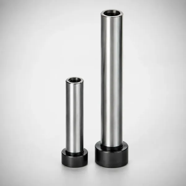
Guidance is usually four post ball cage guide sets with 0.005-0.012 mm running clearance, plus sub-guides on the heaviest punches. Some builders add a second guide set at mid-die for long progressive tools. Anything looser than 0.02 mm lets the strip walk and shifts clearance at the far end of the die, which shows up first as burr on one clock position only.
Feed and press specification
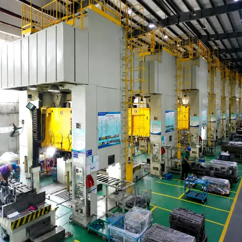
At 1,000 SPM the total cycle is 60 ms. Feed must complete in under 40 ms, which rules out mechanical roll feeds for long progressions and pushes the line to servo feed with ±0.02 mm accuracy or better. A 250 mm progression at 1,000 SPM means the strip is travelling 250 m/min through the die, so straightener capacity, loop control and coil weight of 1-3 t all become part of the tooling decision.
Press sizing for lamination work usually lands at 60-250 t with a 30-60 mm stroke and a hydraulic cushion. Match the press to the die rather than the other way around: check bed deflection under load, ram parallelism, and whether the press holds bottom dead centre within 0.01 mm at full speed. A die that runs clean at 300 SPM and makes burr at 900 SPM usually has a press accuracy or cushion problem, not a die geometry problem.
Strip lubrication is a wear input. Most lines apply a low viscosity evaporative oil at 1-3 g/m² through felt rollers or spray. Too little oil raises galling risk on the slot walls, and too much traps chips and builds up in the die. Keep the film controlled and match it to the coating on the steel, not just to the base material.
Interlocking, Riveting and Stack Height Counting
Once the laminations are cut, the die decides how the stack holds together. The low cost option is a punched interlock: a dimple, lance or V notch formed at the interlock station that presses into the lamination below it. A typical interlock bump penetrates 0.10-0.25 mm into the previous sheet and holds the stack through handling, varnish dip and shaft press fit.
Interlocks carry a hidden penalty. Each interlock bridges the insulation coating and creates a local short path, which raises core loss by roughly 2-5 percent against a bonded stack. The bumps also displace steel, dropping stacking factor from 0.97-0.98 on a glued core to about 0.94-0.96 with dense interlocks. On a 200 lamination stack that difference is 1-2 mm of iron in the same envelope.
Skew control is a stacking requirement, not a die nicety. Rotating each lamination by 1-3 degrees, or using a continuous skew built into the interlock pattern, cancels slot harmonics in the flux path. This is why the interlock station and the part off station must be able to index the loose lamination before it enters the chute. A fixed interlock pattern with no rotation produces a stack that is mechanically sound and electrically noisy.
Stack height then has to be counted or measured. Two approaches dominate: counting strokes or laminations and trusting strip thickness tolerance, or measuring each stack with a sensor and closing the loop. With ±0.005 mm strip, counts are usually within 1 mm of target on a 54 mm stack. With ±0.02 mm strip, the same count can drift 4 mm, and the stacking station needs measurement and trim stations to hit a ±0.5 mm stack tolerance.
For stacks that must survive high speed rotation, joining continues past the die. Through bolts, rivets or laser welds appear at the assembly cell, and each route imposes its own die feature such as rivet holes, weld notches or bolt clearance. Decide the joining route before the strip layout is frozen, because retrofitting a notch station into a proven 20 station die costs weeks of production time.

Bonding Varnish vs Self-Bonding Coatings
Glue free stacking is the fastest growing route for traction motors, because it removes interlock shorts and raises stacking factor. There are two ways to do it, and they are often confused.
Self bonding coatings. The steel supplier applies a heat activated adhesive layer during coating, usually on top of the insulation layer, adding roughly 1-3 µm per side. The die cuts the coated steel normally with no interlock station, and the stacking press cures the bond at 180-250 °C with 0.5-3 MPa of pressure for 2-5 minutes. The stack comes out with a stacking factor of 0.97-0.98 and a bond that resists handling before varnish.
Post assembly varnish. The stack is built loose or lightly interlocked, then dipped or flooded with bonding varnish and cured in an oven, typically 30-60 minutes including ramp. Varnish penetrates the stack and locks laminations together, and it also seals slot edges. The penalties are setup time, drip control and the risk of varnish entering areas that later need welding, bonding or a clean bore.
The third route is laser welding, which is fast and gives high stack stiffness. It also creates a conductive bridge along the weld seam, short circuiting laminations and raising eddy current loss. Weld seam placement and width become an electrical decision as much as a mechanical one, and many traction programs avoid welding on the active magnetic path for that reason.
Whichever route is chosen, the die must match it. A glue free program needs tighter strip flatness control, a stacking press, and chutes that keep laminations aligned before bonding. An interlocked program needs interlock tooling with replaceable inserts, because that station wears faster than any cutting station in the die.
Carbide Edges, Coatings and the Stroke-Life Math
Cutting 0.10-0.35 mm coated silicon steel at high speed pushes most tools to tungsten carbide. Common grades use 6-12 percent cobalt with a submicron grain, giving 89-92 HRA or roughly 1,400-1,600 HV. Powder metallurgy high speed steel at 62-64 HRC is the alternative for thicker stock or lower volume programs, and it typically wears two to five times faster on these coatings.
PVD coatings such as TiAlN or AlCrN at 2-5 µm reduce friction and material pickup on the punch face, which matters most on slot edges where the strip is thin and the contact pressure is high. Edge preparation is equally important: a light hone of 0.01-0.02 mm removes the micro chipping that starts a wear land.
Tool life numbers for planning: carbide edges commonly hold 20-50 million strokes between regrinds on 0.20-0.27 mm coated steel. Regrinding removes 0.05-0.10 mm per pass from the punch or die face, and a well designed die accommodates 3-8 regrinds before the carbide insert is replaced. That puts practical die life at 100-300 million strokes with insert maintenance.
The scale becomes obvious in production terms. At 800 SPM continuous running, a die makes 1,152,000 strokes per day, so 20 million strokes is about 17 days of operation and 50 million strokes is about 43 days. A regrind interval is therefore a monthly maintenance event, not a yearly one. Plan the spare insert set and the regrind fixture before the die is signed off, or the first wear event becomes a two week line stop.
Burr Direction Control and Edge Quality Limits
Burr direction is a hard requirement on lamination work. On a blanked outer contour the burr forms on the die side, and on a pierced hole it forms on the punch side. When every lamination in a stack carries burr in the same orientation, the stack keeps a consistent face for bonding or welding and the burr does not crush the insulation layer next to it.
The limit is usually 0.03 mm maximum, with stator bore and rotor bore edges often specified at 0.02 mm. For scale, insulation coatings run 0.5-3.0 µm per side, so a 0.03 mm burr is 10-60 times thicker than the layer it can bridge. Burr above the limit short circuits laminations and adds eddy current loss, and it also interferes with the stacking chute and the shaft press fit.
Measure burr on the cut edge with a 0.01 mm resolution method: a comparator gauge, a depth micrometer against a surface plate, or an optical system for limits under 0.02 mm. Check it at T1, again at first production, and then on a fixed stroke interval. The detailed clearance and wear mechanics behind burr growth are covered in how to prevent stamping burr, and the same thresholds apply here with tighter limits.
Two failure signatures matter most. Burr that grows evenly across all edges points to normal wear and calls for a regrind. Burr that appears at one clock position, or that flips from the die side to the punch side, points to a chipped edge or to alignment drift above 0.01 mm. The second case is urgent, because a chip in a stator slot punch cannot be dressed in place and usually means pulling the die.
Maintenance, Regrind and Die Life Management
A lamination die earns its keep on a schedule, not on reaction. Set the regrind interval from measured wear, not from a calendar. Pull edge samples every 2-5 million strokes, measure the wear land on the slot punches, and regrind when the land reaches about 0.02 mm on precision cuts or 0.05 mm on general cuts. Burr climbs steeply past those points, and it climbs faster on coated steel.
Rebuild the clearance after every regrind. Removing 0.05-0.10 mm from a punch face changes punch length, not clearance, but grinding the die opening or replacing an insert does change clearance. Re-measure total clearance with a shim or optical method and shim back to the 0.014-0.022 mm target for 0.27 mm stock. A die that comes back from regrind at 12 percent clearance will make acceptable parts for a few hundred thousand strokes and then drift out of print.
Track four numbers per die in a simple register: total strokes, strokes since regrind, stack height deviation at the last audit, and burr height on the last sample. Those four numbers turn maintenance from opinion into planning. They also give the tooling supplier the data needed to adjust clearance or edge grade at the next insert change instead of rebuilding the same failure.
Spare parts should be stocked before the first wear event. A lamination die typically needs one spare insert set for the highest wear stations, a set of pilots, guide post and bush sets for the ball cage guides, and nitrogen cylinders matched to the stripping force. Standard components such as punches, ejector pins and springs ship in 3-7 days, so the only long lead item is the die insert, which takes 2-5 weeks to make and regrind at full accuracy.
Cost Drivers and Lead Time for Lamination Dies
Lamination die price follows station count, edge material and precision, not part size. A 15 station rotor and stator die with PM-HSS edges sits at the low end of the range, while a 25-30 station combination die with carbide inserts, sub-guides, in-die interlock, skew indexing and stack height feedback sits at the high end. Typical industry pricing for traction motor lamination dies runs from roughly $90,000 to $350,000 depending on that configuration, with the edge material and station count driving most of the spread.
Carbide inserts are the biggest single line item, and they are also the biggest life purchase. A carbide grade that costs 40-60 percent more than PM-HSS at build stage can return five to ten times the strokes per regrind, which removes line stops and insert changes over a two year program. Run the trade on strokes per shift, not on purchase price.
Lead time for a lamination die is usually 8-16 weeks including design, machining, wire EDM, carbide grinding, assembly and T1 sampling. Wire EDM capacity and carbide grinding are the usual bottlenecks, because slot geometry on a stator die runs 15-30 stations deep and every station has to match the next within 0.002-0.005 mm. Book the press and the tryout material early, since T1 needs coated production steel, not mill stock.
Insist on one DFM review before cutting steel. A 24 hour DFM loop on strip width, station sequence, interlock placement, skew indexing and stack control prevents the classic late change, where a bonding decision arrives after the interlock station is already ground. Buyers working with an experienced stamping die manufacturer usually see that review turn into a documented station map and clearance sheet before the first plate is machined.
Demand also comes from the motor side. Programs building cores for EV and energy applications often need the die, the stacking line and the bonding process proven together, because a die that measures perfectly on the bench can still fail on a heated stacking press. Plan the validation as a package: strip audit, T1 stack build, core loss sample and burr sample at first production run.
FAQ: EV Motor Lamination Die Questions
Q1. What clearance should an EV motor lamination die run?
Total blanking clearance is typically 5-8 percent of strip thickness, which is 0.010-0.016 mm on 0.20 mm steel and 0.014-0.022 mm on 0.27 mm steel. Thinner high frequency grades below 0.15 mm often land at 0.006-0.010 mm. Confirm the number against the steel supplier coating weight, because harder coatings raise edge wear and can justify running at the lower end of the range.
Q2. How long does a lamination die last between regrinds?
Carbide edges on 0.20-0.27 mm coated silicon steel commonly run 20-50 million strokes between regrinds. At 800 SPM that is 17 to 43 days of continuous operation, so a monthly regrind window is realistic. Wear land should be measured every 2-5 million strokes, with a regrind trigger at about 0.02 mm on precision cutting edges.
Q3. Should I use interlocking or glue free bonding for the stack?
Interlocking is cheaper at build stage and needs no oven or stacking press, but the bumps cut core loss performance by 2-5 percent and drop stacking factor to 0.94-0.96. Self bonding coatings hold 0.97-0.98 stacking factor and no interlock shorts, at the cost of a 180-250 °C curing step with 0.5-3 MPa of pressure. High efficiency traction motors usually justify bonding, and lower volume industrial cores usually do not.
Q4. Why does burr appear at only one position on the lamination?
Localized burr means local damage or local misalignment, not general wear. Usual causes are a chipped slot punch, a slug pulled back into the die, or punch to die alignment drifting past 0.01 mm at that station. Check the strip for slug marks, measure clearance at the affected station, and replace or dress the punch before running more material.
Q5. Can a lamination die run on a standard mechanical press?
Usually no at full speed. Lamination dies are designed for 400-1000 SPM, and they need press bottom dead centre repeatability near 0.01 mm, good ram parallelism, low bed deflection and a hydraulic cushion. A general purpose press that is accurate at 150-200 SPM will typically produce burr and stack height drift well before reaching the die design speed.
The Bottom Line
Lamination dies live or die on clearance, wear measurement and stack discipline. Specify 5-8 percent clearance, 0.03 mm burr limits, counted or measured stacks, and a regrind interval driven by stroke data. DieStrike builds IATF 16949 stamping dies to ±0.005 mm with 8-16 week lead times. Send your lamination drawing for a 24 hour DFM review.
KEEP READING
Related Reading
How to Build a Progressive Die (Step by Step): 8 Steps
From strip layout to station timing, the eight build steps that decide speed, burr and die life before T1.
Read articleArticleHow to Maintain Punch Clearance in Progressive Dies
Clearance drift of 0.01 mm changes burr and tool life. How to measure it and shim back to design.
Read articleArticleHow to Design High-Strength Steel Stamping Dies: Springback, Wear
Hard, abrasive strip drives edge wear and shock loads. The tooling rules that keep dies alive on AHSS.
Read articleServiceStamping Die Manufacturing
IATF 16949 progressive and lamination dies held to ±0.005 mm, delivered in 2-5 weeks.
Read articleNEXT STEP
Ready to Start Your Mold?
Send us your element dimensions or part numbers — our team responds within 24 hours with pricing and lead time.

Written by
Ray ChanMold Buyer's Guide Author · Precision Mold Manufacturing Specialist. Ray helps global importers, distributors and OEMs source factory-direct molds and mold parts.