
How to Grind Mold Steel: Surface, Cylindrical and Jig
Table of Contents
A cavity plate ground 0.02 mm out of shut-height parallelism rarely flashes on the first shot. It flashes at 30,000 cycles, once a 200 °C grind flash has drawn the temper back and HRC 58 has fallen to HRC 46 under the surface. The 0.05 to 0.2 mm soft layer then opens microcracks that seed heat checking in the die face. A re-grind pulls the insert for 3 to 7 days, and a rebuilt insert moves the tool by 2 to 5 weeks. This guide gives the machine, wheel, temperature and cost numbers behind every grinding decision on mold steel.
Each figure below is a shop-typical value for hardened tool steel, and each one needs checking against your own machine, wheel supplier and gauge setup before it goes on a drawing.
The Snapshot
- Grinding owns the last 0.01 mm. Milled faces land at 0.010 to 0.020 mm, hard turning at 0.005 to 0.010 mm, jig grinding at 0.002 to 0.005 mm and surface grinding at 0.002 mm parallelism with Ra 0.2 to 0.4 micron.
- CBN is the only economical wheel above HRC 50. A CBN wheel lives 4 to 20 hours of cutting on hardened steel, against 20 to 60 minutes for a carbide insert in the same material.
- Burn costs you hardness in 0.05 to 0.2 mm. A 150 to 300 °C flash at the contact arc drops HRC 58 to 62 down to HRC 40 to 50 and leaves tensile microcracks 50 to 300 micron deep.
- Steel grows 12 micron per meter per 10 °C. A 300 mm plate that runs 8 °C warmer than the reference reads 0.033 mm oversize, so final grinding runs at 20 plus or minus 2 °C after a 2 to 4 hour soak.
Why Grinding Owns the Last 10 Micron
The accuracy ladder on mold steel is boring and it is real. Rough milling leaves 0.05 to 0.1 mm of slack. Finish milling holds 0.010 to 0.020 mm with a sharp carbide insert and a rigid setup. Hard turning reaches 0.005 to 0.010 mm on a CNC with a CBN insert and a slow feed.
Above that ladder, only the wheel delivers. A good surface grinder holds 0.002 mm parallelism across a plate. A jig grinder holds pilots and dowels inside 0.002 to 0.005 mm with hole-to-hole position under 0.005 mm. Those numbers are where a mold shut-off, a slide contact and a guide-pin fit actually live.

Hardness decides the tool, not the drawing. Up to HRC 35, carbide does almost anything. Above HRC 50 the insert life collapses to 20 to 60 minutes, while a CBN wheel cuts 4 to 20 hours before it needs a re-dress cycle that takes minutes. That is the whole economic argument for grinding hardened steel.
At DieStrike we hold mold work to plus or minus 0.005 mm under an IATF 16949 quality system, and plus or minus 0.002 mm on the EDM and jig-grinding side. Our heat treat goes to HRC 62 max on through-hardened tooling. Every part above HRC 50 that has to carry a functional dimension ends up on a wheel, in our shop or in any other competent one.
The Four Grinding Machines and Their Jobs
Four machines split the grinding work on a mold, and each one owns a shape. The surface grinder takes plates, insert faces and shut-height control. A magnetic chuck holds the plate, the wheel sweeps across in 20 to 40 mm passes, and the table feeds 2 to 10 m/min. It controls 0.002 mm parallelism across a 600 mm plate, which is exactly what a parting line needs.
The cylindrical grinder takes rotating parts: punch pins, ejector sleeves, lifters and core pins. Between centers or in a collet, the part turns at 1 to 4 m/s surface speed while the wheel infeeds 0.002 to 0.005 mm per pass in the finish cut. It holds pin and sleeve diameters to h6 or g6, a band of roughly 0.008 to 0.012 mm on a 10 to 30 mm pin, with Ra 0.1 to 0.2 micron.

The jig borer and jig grinder takes the hole work that must not drift. Pilots, dowel bores and bushing seats come in at H7 within 0.002 to 0.005 mm, and hole-to-hole position stays inside 0.005 mm. A hardened mold plate with ten dowel holes ground on the jig grinder holds its stack-up; the same plate bored after hardening on a mill will not.
The internal grinder takes bores: guide-pin bushings, sprue bushings and small cavities a wheel can reach. Through-feed ID grinding delivers 0.002 mm on the bore with a finish below Ra 0.15 micron, which is what a bushing needs so a pin slides without galling. Infeed grinding covers shoulders and bores with a step.
One more number binds all four: wheel access. A 30 mm deep blind corner with a 0.3 mm radius is not a grinding problem at all, because no wheel narrower than the corner gets there. That is a wire EDM job, discussed below.
Wheel Selection: Abrasive, Grit and Grade
The abrasive is chosen by what the wheel touches, not by the machine label. Aluminum oxide (A) cuts soft steel, pre-hardened blocks under HRC 35 and mild-steel mold bases, and it costs a fraction of the superabrasives. Silicon carbide (C or GC) takes carbide tips, brass and non-ferrous parts where aluminum oxide loads and smears.
CBN (borazon) owns hardened tool steel from HRC 45 to 65. It is chemically inert against iron, so it does not carbonize the face the way silicon carbide does on steel. Diamond owns carbide and ceramics, and on mold shops you meet it mostly dressing carbide-tipped parts, not grinding H13.
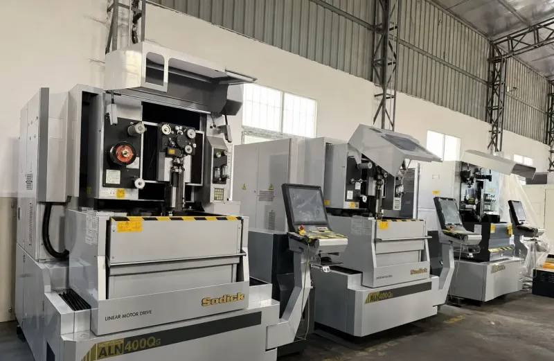
Grit is a stock-removal decision. On a CBN wheel, 4 to 8 grit runs roughing at 0.01 to 0.02 mm per pass. 16 to 32 grit runs the finish cut at 0.002 to 0.005 mm per pass. 60 to 120 grit is mirror-prep work, the pass that takes Ra 0.4 down toward Ra 0.1 before hand-polishing on an optical face.
Grade hardness (the soft E to hard Z letter scale) is a coolant-access decision. When the wheel is fully flooded and the arc is short, run a harder grade for form life. When coolant access degrades, deep pockets, small internal diameters, wet peripheral grinding with a chilled nozzle aimed at the arc, soften the grade one to two letters. A hard grade starved of coolant rubs, and rubbing is how 150 to 300 °C happens.
The work-speed and feed map keeps you out of burn. High work speed with light infeed raises the chip-temperature split toward the chip instead of the part. As a shop rule: rough at 0.015 mm with generous flood, finish at 0.005 mm or less, table or work speed up, and never take a final cut dry to "see the size."
Grinding Burn and What It Destroys
Grinding burns because the contact arc is hot. At 150 to 300 °C, the tempered martensite under the surface draws its temper a second time. A face hardened to HRC 58 to 62 reads HRC 40 to 50 inside 0.05 to 0.2 mm of the ground surface, and the soft layer is invisible until a hardness test or an acid etch finds it.
Burn does not stop at softness. The re-drawn layer wants to expand against cold steel beneath it, so it locks in tensile stress and opens microcracks 50 to 300 micron deep. In a die face those cracks are heat-check seeds: the same failure that a hot-runner-adjacent insert picks up after tens of thousands of cycles starts there.
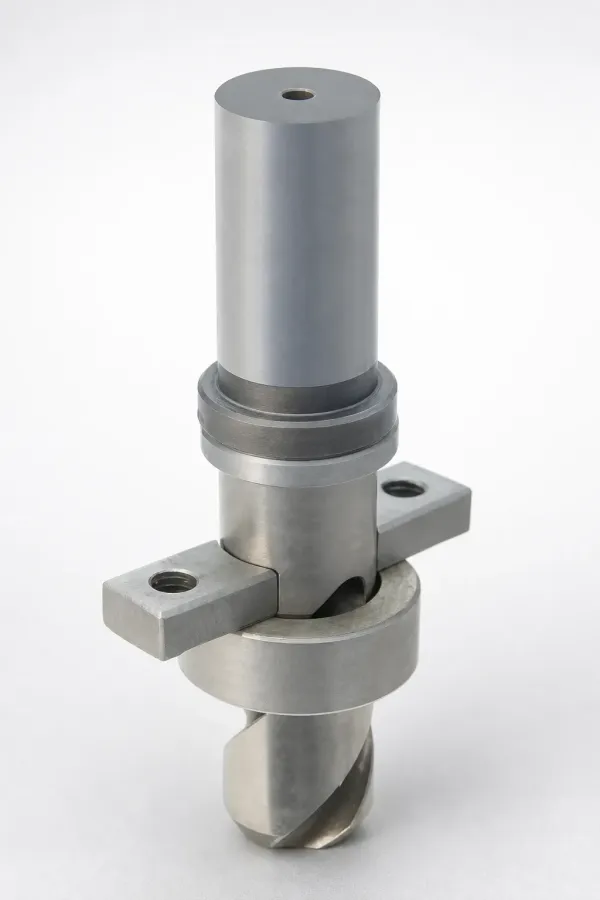
Detection has three honest routes. Nital etch (a 2 to 5 percent nitric acid in alcohol swab, 1 to 3 minutes) smokes or darkens exactly where the temper drew; a burn spot as small as 0.05 mm shows. The Al2O3 fire-test smear, a slurry cooked on a sacrificial tab in a hot bath, pulls the same stain out as a color band and suits oddly shaped inserts. XRD residual-stress measurement puts real numbers on the stress layer, at 2 to 5k USD per setup, and it earns its keep on Class A die faces and automotive cavity inserts.
Prevention is a sequence, not a wish. Remove stock in two passes, 0.015 mm roughing then 0.005 mm finishing. Run high work speed, keep the nozzle on the arc, and dress the wheel every 20 to 40 parts, or whenever the sparks turn from white and sparse to orange and dense. A glazed wheel is a burner, and a burner is a scrapped insert.
Thermal Growth and Shop Arithmetic
Steel grows 11 to 12 micron per meter for every 10 °C. A 300 mm plate running 8 °C warmer than the gauge reference is 0.026 to 0.033 mm oversize before the wheel touches it. That single fact is worth more than any machine spec, because 0.033 mm is sixteen times your 0.002 mm tolerance.
Do the arithmetic on a 600 mm mold plate and the number moves above 0.05 to 0.07 mm. A plate ground hot on the machine reads perfect at the spindle and undersize when it cools on the inspection table. The shop standard follows directly: grind final dimensions at 20 plus or minus 2 °C, soak the part 2 to 4 hours after heat treat and again after rough grinding, and hold the last cut on a cold machine.
Soak time is not dead time you can bill away. Post-heat-treat parts come out of the furnace at ambient-plus and keep moving for hours; a jig job clamped straight off the quench drifts while you grind it. Rough grind, soak 2 to 4 hours, stress-relieve if the print asks for it, then finish grind. The sequence is written out pass by pass in the guide to machining mold steel before and after heat treat.
Machine warm-up belongs to the same arithmetic. A surface grinder out of overnight takes 20 to 40 minutes of idle running before the table position repeats within 0.002 mm, because the ball screws and the column carry the same 11 to 12 micron per meter per 10 °C growth as your workpiece. Cold-machine checks and warm-machine checks are different machines.
Grinding Versus EDM: Election by Feature
The election rule is short: grind for accuracy on a functional face, use EDM for geometry. Grinding gives you the 0.002 mm and the Ra 0.2 micron on a surface a part or a guide actually touches. EDM gives you the corner, the depth and the shape a wheel cannot physically reach.
Wire EDM takes the through-hardened blind corners and any internal radius under 0.3 mm, because a 0.3 mm corner needs a wheel under 0.6 mm wide and no one grinds mold steel with that much patience. The wire route, its kerf and its corner numbers, is written up in wire EDM for mold making. Grinding takes the 0.4 mm land on a slide contact face, the shut-off band on a cavity, and the seating face of an ejector sleeve, because wire leaves a recast skin and a 0.2 micron-plus surface that a slide contact does not want.
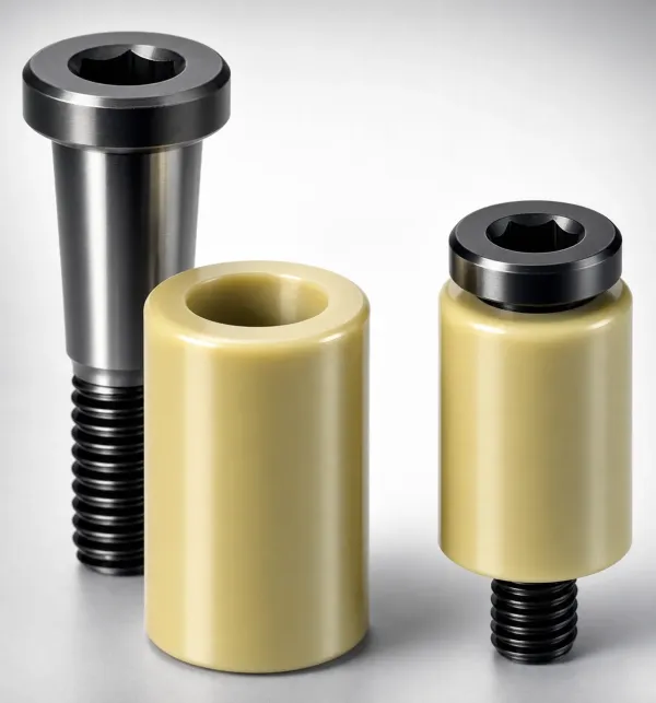
Deep cavity floors get hard-milled first, then ground only where the shut-off or datum sits. Milling 0.3 mm of stock off a floor at 200 mm reach costs a fraction of grinding the same stock, and the floor 5 mm from a parting line never carries a functional dimension. The mill-versus-spark logic on those floors follows the comparison in hard milling versus EDM.
Coatings change the election after the fact. Never grind away a nitrided or PVD layer without re-coating: a 0.02 mm nitride case is gone under one 0.015 mm roughing pass, and the face under it is bare 420 or H13. If a dimension has to move after coating, either plan the grind before heat treat and coating, or pay to strip and re-apply, which is 3 to 7 days.
Stock Removal Cost per Part
Shop rates put the decision in money. Surface grinding runs 8 to 20 USD per machine hour at 0.005 to 0.02 mm per pass. A cylindrical grinder finishes a punch pin or ejector sleeve for 2 to 8 USD per part on a lot that repeats. A jig-ground hole cluster, pilots and dowels together with bushing seats, runs 40 to 90 USD per cluster on a mold plate.
The hidden line is the overhead. Wheel changes, dressing cycles and setup alignment eat 20 to 40 percent of spindle time on short lots, and the percentage falls only when the same wheel runs 50 identical parts. On a one-off repair insert, plan 1.5 to 2 times the pure cutting hours before you quote it.
Compare that to the alternative before defaulting to the wheel. A 90 USD jig-ground pilot cluster is cheap against a hand-bored plate that drifts 0.05 mm and forces a fit-up rework of 6 to 10 hours. A 20 USD grind pass on a shut-off is cheap against flash that stops a molding line for a shift. Grinding buys back those hours; it only makes sense when the feature needs its accuracy.
Process Selection by Feature and Tolerance
Use this table to route each feature before the shop packs the fixture. The tolerance column is the realistic single-machine capability, not a best-ever demonstration part.
| Mold feature | Machine | Tolerance held | Finish | Wheel or note |
|---|---|---|---|---|
| Plates, shut height, parting face | Surface grinder | 0.002 mm parallelism | Ra 0.2 to 0.4 micron | CBN above HRC 50, 16 to 32 grit finish |
| Punch pins, sleeves, lifters | Cylindrical grinder | h6 or g6 (0.008 to 0.012 mm) | Ra 0.1 to 0.2 micron | 0.002 to 0.005 mm finish infeed |
| Pilots, dowels, bushing seats | Jig borer and grinder | H7 within 0.002 to 0.005 mm | Ra 0.2 micron | Hole-to-hole inside 0.005 mm |
| Guide-pin bore, sprue bushing bore | ID grinder | 0.002 mm on the bore | Below Ra 0.15 micron | Through-feed; wheel must reach the depth |
| Blind corner, radius under 0.3 mm | Wire EDM | 0.002 to 0.005 mm | Ra 0.4 to 0.8 micron | Geometry job, not an accuracy-on-a-face job |
| Deep cavity floor away from shut-off | Hard mill | 0.010 to 0.020 mm | Ra 0.8 micron | Grind only where the datum lands |
← swipe to scroll →
Table note: capability bands are typical for a rigid machine, a dressed wheel and a soaked part at 20 plus or minus 2 °C. Confirm against your own gauge R&R before writing a print callout.
Measurement at 0.002 mm
A 0.001 mm micrometer cannot certify a 0.002 mm tolerance. The operator, the temperature and the anvil wear together eat most of the resolution the dial claims. At this level you measure with a CMM or an air gauge, not with bench hands.
A CMM with a 25 mm stylus and a 0.5 to 1 micron repeatability checks plate parallelism and hole position in one setup, and it logs the numbers for the FAI. An air gauge reads pin and bore diameters to 0.001 mm or better with no operator force error, which is why h6 pins and H7 bores get their pass or fail from the air go and no-go ring, not the mic. The discipline behind both is in how to hold 0.002 mm precision mold tolerances.

Temperature-compensate everything, and mean it numerically. The CMM software compensation assumes the part sits at 20 °C; a plate that reads 24 °C on a contact probe carries its own 0.013 mm lie per 300 mm of length before the gauge does anything wrong. Record the part temperature next to the size on the FAI sheet.
Then record the burn check next to it. On Class A die faces, the FAI or first-article inspection carries the nital or fire-test result and, where the customer pays, the XRD stress number from the sacrificial tab ground in the same setup as the part. Every number on that sheet comes off the same cold, soaked part the wheel finished.
Before-You-Grind Checklist
Run this list against the print before a hardened part is ever chucked. Every line is a number, because a checklist without numbers is a wish.
- Heat treat certificate read. Confirm the hardness callout: HRC 45 to 62 means CBN territory, and anything above HRC 50 kills the carbide option at 20 to 60 minutes of insert life.
- Soak logged. 2 to 4 hours after heat treat and again after rough grinding, with the part at 20 plus or minus 2 °C before the final cut.
- Stock plan written. 0.015 mm roughing pass then 0.005 mm finishing pass, never a single cut that takes the last 0.02 mm.
- Wheel matched. Abrasive for the material, 4 to 8 grit for removal, 16 to 32 for finish, 60 to 120 for mirror-prep, grade softened when coolant access is poor.
- Dress interval set. Every 20 to 40 parts, or on any color change in the spark stream from white to orange.
- Burn check scheduled. Sacrificial tab in the same setup, nital or fire-test result recorded; XRD at 2 to 5k USD per setup on Class A faces.
- Coating sequence respected. Finish grind before nitriding or PVD, and any post-coating grind re-covers the full 0.02 mm case.
- Gauge chosen. CMM or air gauge for 0.002 mm work, micrometers downgraded to in-process checks only.
The checklist also settles the argument with the drawing. A 0.002 mm callout on a face nobody contacts is money burned on a wheel; a 0.02 mm callout on a slide land is a warranty claim waiting for cycle 30,000. Price the feature by function, then pick the machine from the table above.
The Bottom Line
Grinding owns the last 0.01 mm of a mold, and it fails in two ways: burn and drift. The burn pathway is fixed by the two-pass rule at 0.015 and 0.005 mm, high work speed, flood coolant on the arc and a dress every 20 to 40 parts, because a 150 to 300 °C flash draws HRC 58 to 62 down to HRC 40 to 50 inside 0.05 to 0.2 mm. The drift pathway is fixed by the 20 plus or minus 2 °C room, the 2 to 4 hour soak and the cold final cut, because steel moves 11 to 12 micron per meter per 10 °C.
Route the work by machine and by money. Surface grinder for the 0.002 mm plate, cylindrical for h6 and g6 pins at 2 to 8 USD each, jig grinder for H7 pilots inside 0.005 mm hole-to-hole, ID grinder for bushing bores below Ra 0.15 micron, and wire EDM whenever the feature is geometry rather than a functional face. At DieStrike we make molds and dies to plus or minus 0.005 mm under IATF 16949, with plus or minus 0.002 mm on EDM and jig grinding, HRC 62 heat treat, 120+ machines, standard components in 3 to 7 days and tool leads of 2 to 5 weeks, trusted by tier-1 names including TE, Amphenol, Luxshare and Dongshan. Send the print through injection mold manufacturing and the grinding callouts come back priced by feature, not by habit.
KEEP READING
Related Reading
How to Machine Mold Steel Before and After Heat Treat
Where roughing, stress relief and hardening sit in the sequence that ends at the grinder.
Read articleArticleHard Milling vs EDM
The cutter, electrode and tolerance numbers behind the mill or EDM election on hardened steel.
Read articleArticleWire EDM for Mold Making
Kerf, corner radius and accuracy data for the wire work that replaces internal grinding.
Read articleServiceInjection Mold Manufacturing
IATF 16949 mold making with plus or minus 0.005 mm accuracy and plus or minus 0.002 mm on jig grinding.
Read articleNEXT STEP
Ready to Start Your Mold?
Send us your element dimensions or part numbers — our team responds within 24 hours with pricing and lead time.

Written by
Ray ChanMold Buyer's Guide Author · Precision Mold Manufacturing Specialist. Ray helps global importers, distributors and OEMs source factory-direct molds and mold parts.