
Wire EDM for Mold Making: Accuracy, Surface, and Cost
Table of Contents
Every mold has a handful of features that decide whether first trial is a formality or a two-week fight. Internal corners on a cavity insert are usually first on the list. A Ø3 mm end mill leaves a 1.5 mm radius, and every micron of that radius the drawing did not allow comes back later as a visible blend line, a gate that opens late, or a shut-off that flashes after 10,000 shots. Shops without wire EDM solve this at the bench with hand blending — and hand blending produces inserts that each differ by a few microns from the next one in the same cavity set.
Wire EDM machining removes the guesswork. Instead of a rotating cutter, it uses a 0.1-0.3 mm electrode wire and erodes the metal with controlled sparks, so an internal corner radius drops to the wire radius plus the 0.02-0.05 mm discharge gap — about 0.15 mm with common 0.25 mm brass wire, and under 0.1 mm with a 0.1 mm wire. That single geometric fact is why wire EDM is standard practice for precision inserts, ejector pin holes, and stamping die edges in every serious mold shop. This guide covers the accuracy grades, surface finishes, cost drivers, and RFQ details that decide whether your wire cut EDM job ships on spec or gets re-cut.
The Snapshot
Wire EDM for mold making in numbers:
- ±0.002-0.005 mm positioning is standard on mold-grade wire EDM machines (published machine data); ±0.001 mm is achievable on qualified machines with wire compensation and thermal control.
- Internal corner radius = wire radius + gap: about 0.15 mm with 0.25 mm wire, 0.07-0.1 mm with 0.1 mm wire — geometry a rotating cutter physically cannot reach.
- Surface finish runs Ra 2.5-3.5 µm after the rough cut down to Ra 0.2-0.8 µm after 3-5 skim passes; fine trim conditions reach Ra 0.1 µm, and mirror finishing around Ra 0.02 µm is sinker EDM territory.
- Rough-cut speed of 20-40 mm²/min is typical in 40-80 mm mold steel; each skim pass adds roughly 20-40% of rough-cut time to the cycle.
- A recast (white) layer of 2-5 µm forms on the rough cut — brittle and micro-cracked; skim passes remove most of it before stamping edges and shut-off faces see service.
- Taper cutting to ±15° is standard on production machines (more with 0.1 mm wire), covering die relief, insert draft, and sprue bushing tapers in one setup.
Why Mold Shops Rely on Wire EDM
Without wire EDM, three categories of mold features quietly become risk. First, sharp inside corners: any corner radius smaller than the cutter radius forces a smaller tool or bench work, and below roughly 0.3 mm there is no practical end mill — the feature either takes a bigger radius than the drawing allows or gets hand-finished, which means every cavity comes out slightly different. Second, straight holes and slots in hardened steel: ejector pin holes of Ø0.8-3 mm run through 40-80 mm of steel at 48-62 HRC, where twist drills wander and grinding cannot reach into the bore. Third, interchangeability: a six-cavity mold needs six inserts that seat identically; hand-finished inserts drift by microns, and the mismatch shows up as unbalanced part quality and a longer, costlier tryout.
The failure mode is expensive. A non-interchangeable insert means rework at full mold-shop rates, a trial schedule that slips, and molded parts that measure differently from cavity to cavity — exactly what a customer's PPAP audit will find. Wire EDM removes the operator judgment: the same program, the same wire path, and the same compensation produce insert after insert within ±0.002-0.005 mm, cut after the steel is already hardened to 48-62 HRC, so there is no heat-treatment distortion after finishing. Our custom mold inserts are cut this way, which is why they seat and interchange without fitting work.
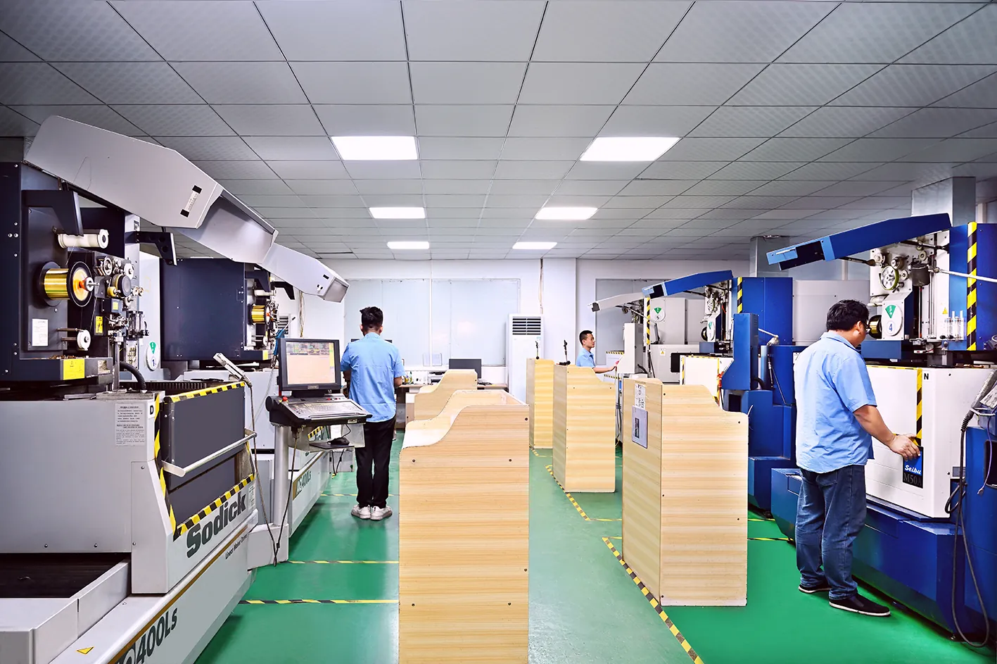
Wire EDM Basics: How the Process Cuts
Wire EDM (electrical discharge machining) erodes material with controlled sparks, not cutting forces. A brass or zinc-coated wire 0.1-0.3 mm in diameter feeds continuously from a spool at roughly 8-12 m/min while the machine drives it along the programmed contour; the wire never touches the workpiece. Each spark vaporizes a tiny volume of metal in the discharge gap — the total kerf for common 0.25 mm brass wire is 0.02-0.05 mm, i.e., wire diameter plus two spark gaps — and the deionized-water dielectric flushes the debris away.
Because there is no tool pressure, there is no deflection, no burr, and no work-hardened edge. The process cuts anything conductive regardless of hardness: P20, H13, S136, and D2 at 48-62 HRC, even carbide. Harder steels cut slightly slower but hold the same positioning accuracy — one reason wire EDM became the default for finishing after heat treatment. The trade-off is speed: 20-40 mm²/min is a typical rough-cut rate in 40-80 mm mold steel, and finish passes drop to a few mm²/min. Steel grade still matters for cutting behavior and cost, which is why the P20 vs H13 vs S136 comparison is worth reading before you lock the material call-out.
The machine moves the upper and lower wire guides independently, so the cut can tilt. Tapers to ±15° are standard on production machines; 0.1 mm wire and special heads extend that toward ±30°. Mold shops use modest angles — 0.5-2° relief on stamping die plates, 1-5° draft on insert walls, full sprue bushing tapers — cut in the same program as the profile, with no secondary operation.
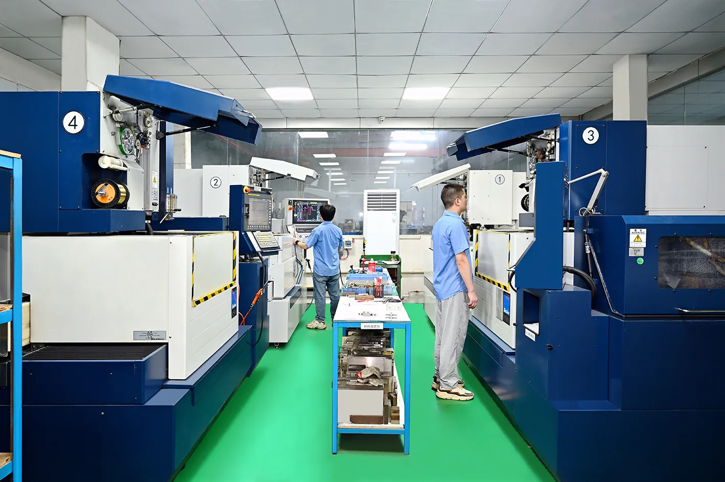
Accuracy Grades: What ±0.002 mm Actually Requires
A positioning spec of ±0.002-0.005 mm is common on mold-grade wire EDM machines (published machine data), and qualified machines with glass scales and thermal compensation claim ±0.001 mm. But delivered accuracy is a process result, not a machine spec. What converts machine potential into a part that measures right on the CMM:
- Wire compensation per spool. Kerf changes with wire diameter tolerance and wear; a fresh spool and a nearly empty one cut different slot widths on the same path. The program must be compensated for the wire actually on the machine.
- Skim pass strategy. The rough cut positions; the skim passes correct geometry. Cutting finish features on the first pass is how 0.01 mm of taper sneaks into a 50 mm deep cut.
- Thermal control. A wire EDM cutting for hours drifts with shop temperature; a 1-2 °C swing is enough to matter on long cuts. Temperature-controlled shops and warm-up cycles protect ±0.002 mm features.
- Verification at 20 °C. The profile only counts as spec after CMM or vision measurement at reference temperature with the drawing datums — that is why every critical DieStrike feature gets CMM verification.
| Cut Strategy | Positioning Accuracy | Surface Ra | Recast Layer | Typical Mold Use |
|---|---|---|---|---|
| Rough cut (1 pass) | ±0.010-0.020 mm | Ra 2.5-3.5 µm | 2-5 µm | Slug removal, stock cutting, non-functional perimeters |
| Semi-finish (2-3 passes) | ±0.005 mm | Ra 0.8-1.5 µm | Thin or removed | Ejector pin holes, dowel holes, insert side walls |
| Finish (4-5 passes) | ±0.002-0.003 mm (±0.001 mm with compensation) | Ra 0.2-0.4 µm | Essentially eliminated | Parting surfaces, shut-offs, stamping die cutting edges |
← swipe to scroll →
Specifying accuracy is a per-feature decision. Putting ±0.002 mm on every hole doubles cycle time for no benefit; putting it on the features that mate with other components protects the assembly. We assign accuracy classes during the free 24-hour DFM review and say plainly which features need finish-grade cutting — the same discipline that keeps the tolerance chain intact on our precision mold work, covered in detail in how to hold ±0.002 mm tolerances. The wire floor is complemented by Waida jig grinders that hold 0.0005 mm for features needing sub-micron geometry; the full equipment list is on our capabilities page.

Surface Finish and the White Layer
The rough cut leaves Ra 2.5-3.5 µm and a recast layer 2-5 µm thick: molten metal that re-solidified on the surface. It is harder than the base steel, brittle, micro-cracked, and in tension. On a stamping die cutting edge, a recast layer is where chips start; on a shut-off face, it is where flash initiates. For most mold work, skim passes exist to remove it: each pass re-cuts the surface with gentler parameters, lowering Ra and stripping the recast until, after 3-5 passes, Ra sits at 0.2-0.8 µm with the recast layer essentially gone.
| Surface Finish | How Achieved | Typical Mold Application |
|---|---|---|
| Ra 2.5-3.5 µm | Single rough cut | Slug cutting, stock removal, hidden perimeters machined later |
| Ra 0.8-1.5 µm | 2-3 passes (skim 1-2) | Ejector pin holes, dowel holes, insert walls that seat in pockets |
| Ra 0.2-0.4 µm | 4-5 passes (skim 3-4) | Parting surfaces, shut-offs, visible molded areas, stamping die cutting edges |
| Ra 0.1 µm and below; mirror Ra 0.02-0.05 µm | Fine trim / sinker fine finishing | High-gloss cavities, optical and light-guide surfaces |
← swipe to scroll →
For critical stamping dies and heavily stressed inserts, industry practice is a low-temperature temper at roughly 180-250 °C after the rough cut and before finish cutting, which relaxes the tensile stresses the recast layer leaves behind (published EDM practice). Skipping it is how an edge that measured fine at receipt chips in the first production run. If an EDM-cut edge does break down, the damage pattern — chipping along the recast line rather than uniform wear — is usually visible on inspection; that distinction matters when you decide between re-cutting and mold repair.
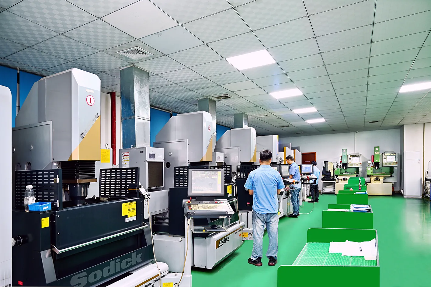
Wire EDM vs Sinker EDM
Both processes erode with sparks, but they serve different geometry. Wire EDM cuts through features — profiles, holes, slots — with a continuously fed wire; sinker EDM burns a shaped electrode into the work to produce blind cavities and 3D forms. A sculpted core with deep ribs is sinker work; the insert perimeter around it, and every hole in the hardened plate, is wire work. Most molds use both, and the "sinker edm vs wire edm" question is really a per-feature decision.
| Aspect | Wire EDM | Sinker EDM |
|---|---|---|
| Best geometry | Through profiles, holes, slots, tapers | Blind cavities, deep ribs, sculpted cores |
| Corner radius | Wire radius + gap, about 0.1-0.15 mm | Electrode corner; sharp internal corners achievable |
| Accuracy | ±0.002-0.005 mm positioning typical | ±0.005 mm typical; improves with planishing passes |
| Surface finish | Ra 0.2-0.4 µm with 4-5 passes; Ra 0.1 µm with fine trim | Ra 0.2-0.8 µm standard; mirror Ra 0.02 µm with fine finishing |
| Tooling cost | None — wire only | Machined graphite or copper electrode per cavity |
| Typical mold use | Insert profiles, ejector holes, die edges, tapers | Core and cavity forms, mirror cavities, ribs and text |
← swipe to scroll →
The cost split follows geometry. Wire EDM has no electrode to machine, so it is usually the cheaper route for anything that is a through feature. Sinker EDM pays for the electrode — machining time, material, and wear compensation — but it is the only practical process for a blind cavity. Choosing by feature instead of by habit is where mold cost is actually controlled; our injection mold manufacturing process pairs both machines on the same tool, with wire EDM handling the perimeter and holes while sinker EDM forms the cavity itself.
Wire EDM in Mold Making: Typical Applications
- Insert profiles. Cavity and core inserts cut to ±0.002-0.005 mm after hardening — six identical inserts for a six-cavity tool, internal corners of 0.1-0.15 mm where the part drawing demands them. This is the core of our custom mold insert work.
- Ejector pin holes and sleeve pockets. Straight, draft-free holes of Ø0.8-3 mm through hardened plates, positioned to ±0.005 mm, spaced closer than any drill can manage. Square pockets for ejector sleeves; walls of 0.5 mm between adjacent holes survive because the kerf is only 0.02-0.05 mm wider than the wire. The pins that run in these holes are covered in our ejector pin selection guide.
- Gate and runner inserts. Gate slots with sharp corners, hot runner tips, and sprue bushings with their taper cut in the same program.
- Stamping die cutting edges. Punch and die profiles with per-side clearance of 5-10% of stock thickness (published die design practice), 0.5-2° relief taper, and cutting edges finished to Ra 0.2-0.4 µm so recast does not chip at the shear line. Progressive die plates with dozens of punch openings are cut in one setup.
- Taper cutting. Relief angles, insert draft, and guided ejector features in a single pass; ±15° machine capability covers typical mold angles with margin.
The common thread: every one of these features is defined by a 2D profile, cut after hardening, and repeated identically. That is precisely the job wire EDM does better than any alternative — which is why it appears at every stage of a DieStrike mold build, from prototype inserts to production stamping dies.

Cost Drivers and Cycle Time
Wire EDM cost is dominated by machine hours, and machine hours are dominated by cut area and pass count. Rough cutting runs 20-40 mm²/min in typical 40-80 mm mold steel; finish passes drop to a few mm²/min. A 200×200 mm insert perimeter (0.8 m of cut path) in 50 mm steel is 40,000 mm² of cut area — roughly 1.5-2 hours of rough cutting plus 2-4 hours of skim passes at typical published rates. Doubling the finish spec on every feature can add 50% or more to the EDM cycle.
- Cut area. Perimeter times thickness is the number that drives hours; a long thin-wall profile costs more than a compact block of the same mass.
- Wire consumption. Wire feeds at 8-12 m/min and is discarded as it cuts; a 5 kg spool of 0.25 mm brass wire is roughly 10,000 m (published wire data). Wire typically lands at 10-20% of total job cost. Zinc-coated wire cuts 20-30% faster but costs more per meter — the trade usually favors coated wire on thick blocks.
- Corner density and tapers. The machine slows at every corner to hold the programmed radius, and taper cuts run slower; a profile with 40 corners cuts slower than the same perimeter as a rectangle.
- Setup and verification. Threading the wire through start holes, flushing on thick cuts, and the first-article CMM check are fixed costs that matter most on small jobs.
The practical lever is specification discipline. Put finish-grade cutting and ±0.002 mm only on the features that need them, state the skim-pass count explicitly, and the shop can quote a cycle instead of padding for unknowns. That is why we ask for the part file up front: the 24-hour DFM review assigns accuracy classes and pass counts feature by feature, so the quote reflects the real process — the same way every operation is budgeted in a full mold build.
How to Spec Wire EDM on Your RFQ
Wire EDM work is easy to under-specify and expensive to re-specify. A complete wire EDM line item on your RFQ has seven parts:
- Material and hardness — for example "S136, hardened to 48-52 HRC". Hardness changes cutting parameters and skim-pass behavior.
- Geometry file — DXF or STEP of the 2D profile, with start-hole locations and slug-removal constraints.
- Accuracy class per feature — ±0.005 mm standard, ±0.002 mm for mating features, ±0.001 mm only where the assembly demands it.
- Surface finish and pass count — "Ra 0.4 µm, three skim passes" beats "nice finish"; pass count is what you can audit.
- Corner radius requirement — state the minimum internal radius so the shop picks the right wire size: 0.25 mm wire for standard work, 0.1 mm for sub-0.1 mm corners.
- Taper angle and direction — if any, with the reference plane it is measured from.
- Verification method — CMM report at 20 °C with datums matching the drawing; agree on how it is measured before cutting, not after.
Two things buyers routinely forget. First, slug drop: in a rough cut the slug falls free and can score the finished surface — specify whether the slug must be held or which side of the part matters. Second, wire EDM leaves a start hole that must be plugged or placed where it is acceptable; a machined start hole is a standard add-on, not a defect. Send the full mold context — material, heat treatment, mating components — and the quote stops being a guess. Our injection mold manufacturing service shows how wire EDM slots into the full build, from DFM to delivery.
FAQ
| Question | Short Answer |
|---|---|
| How accurate is wire EDM for mold work? | ±0.002-0.005 mm positioning is standard on mold-grade machines; ±0.001 mm is achievable with wire compensation and thermal control, and CMM-verified. |
| What surface finish can wire EDM achieve? | Ra 0.2-0.8 µm after 3-5 skim passes, Ra 0.1 µm with fine trim conditions; mirror finishes around Ra 0.02 µm come from sinker EDM fine finishing. |
| Wire EDM or sinker EDM for my mold? | Through features — profiles, holes, slots — are wire work; blind cavities and sculpted forms are sinker work. Most molds need both; choose per feature, not per mold. |
| Does wire EDM leave a recast layer? | Yes, 2-5 µm after the rough cut; skim passes remove most of it. Critical stamping dies get a 180-250 °C stress-relief temper between rough and finish cutting. |
| What is the smallest internal corner radius? | Wire radius plus discharge gap: about 0.15 mm with 0.25 mm wire, 0.07-0.1 mm with 0.1 mm wire. |
← swipe to scroll →
The Bottom Line
A mold without wire EDM pays its risk in blended corners, drifting insert fit, ejector holes that walk in hardened steel. DieStrike runs Sodick wire EDM with multi-pass skim cutting to Ra 0.2-0.4 µm, mirror-grade finishing to Ra 0.02 µm, and CMM verification on critical features.
KEEP READING
Related Reading
Climb vs Conventional Milling: Mold Shop Choice
Climb milling cuts from maximum chip thickness down to zero; conventional milling cuts from zero up to maximum.
Read articleArticleInjection Mold Manufacturing Process: From Drawing to Trial in 7 Steps
Every injection mold follows the same sequence: DFM review, mold design and flow analysis, steel order, rough…
Read articleArticlePrecision CNC Machining for Mold Components
Precision CNC machining for mold components: tolerance classes from ±0.005 mm standard to ±0.002 mm critical and 0.
Read articleArticle5 Mold Cooling Channel Design Tips for Faster Cycles
Mold maker's 5 cooling channel design rules: channel-to-cavity distance 2-2.
Read articleNEXT STEP
Ready to Start Your Mold?
Send us your element dimensions or part numbers — our team responds within 24 hours with pricing and lead time.

Written by
Ray ChanMold Buyer's Guide Author · Precision Mold Manufacturing Specialist. Ray helps global importers, distributors and OEMs source factory-direct molds and mold parts.