
Climb vs Conventional Milling: Mold Shop Choice
Table of Contents
A single wrong milling direction on a hardened cavity costs more than one cutter. On an S136 cavity at 48-52 HRC, one conventional (up-milling) finishing pass can rub the steel at entry instead of shearing it, work-harden a 0.02-0.05 mm surface layer, leave a smeared finish at Ra 0.8-1.6 µm where the drawing asks for 0.4, and burn the edge of a 12 mm carbide ball-end mill in a single run. The visible cost is the tool; the hidden cost is a cavity that re-polishing cannot fully rescue, because the damage is in the steel surface, not on it.
On the opposite side of the same coin, climb milling on the wrong stock is how first-pass cutters chip: a climb pass striking a scaly, cast, or oxide-covered block engages the hard outer layer at maximum chip thickness, and the cutting edge takes the full impact load before it has cut anything. Both directions are correct in their own situation, and the difference between a clean mold and a re-cut is knowing which situation you are in before the spindle turns.
This guide is for mold buyers, product engineers, and mold engineers who need the mechanics and the numbers: what each direction does to chip thickness and cutting forces, when climb wins, when conventional milling is mandatory, typical speeds and feeds for P20, 718H, S136, and H13, realistic Ra values, and how a mold shop sequences the decision on the floor. All parameters below are industry-typical starting points for coated carbide tooling, meant to be validated against your tool supplier, machine, and rigidity — not guarantees for a specific setup.
The Snapshot
- Chip-thickness direction is the whole story: climb (down) milling cuts from maximum chip thickness down to zero; conventional (up) milling cuts from zero up to maximum. Surface finish, force direction, burr, and wear all follow from that single fact.
- Climb finishing on machined mold steel typically lands Ra 0.4-0.8 µm with a 12 mm ball-end mill; the same pass in conventional milling typically lands 0.8-1.6 µm with visible feed marks and a larger exit burr.
- Climb milling pushes the workpiece down into the table and shears clean at exit; conventional milling lifts the work and rubs at entry — the rubbing is what work-hardens stainless-class grades such as S136 and burns edges above 45 HRC.
- Conventional milling is required when the stock carries scale, oxide, or cast skin, when the machine has measurable backlash, or when cuts cross hard interrupted edges — the zero-thickness entry protects the edge from impact.
- Typical coated-carbide starting points (12 mm cutter reference): P20 at 28-34 HRC roughs at 300-450 SFM and 0.06-0.10 mm/tooth; hardened H13 and S136 at 46-52 HRC finish at 200-350 SFM and 0.01-0.03 mm/tooth.
- Above roughly 45 HRC, finishing is climb-only in practice: conventional milling's entry rubbing phase is exactly what destroys edges on hardened mold steel.
- DieStrike programs climb finishing on every cavity finish pass, reserves conventional milling for the scale pass and backlash-limited operations, and verifies machined surfaces with a profilometer before polishing.
What Climb and Conventional Milling Are
Climb milling, also called down milling, rotates the cutter in the same direction as the feed. Each tooth enters the material at maximum chip thickness — roughly equal to the feed per tooth for a 90-degree end mill — and exits at zero. The chip starts thick and ends thin. Conventional milling, also called up milling, rotates the cutter against the feed: each tooth enters at zero chip thickness, rubs until the chip builds, and exits at maximum chip thickness. The chip starts thin and ends thick.
The names describe the cutter's mechanical tendency, which is the practical point. Climb milling pulls the workpiece toward the cutter — the cutter "climbs" onto the work, and the tangential cutting force has a component in the feed direction. Conventional milling pushes the workpiece against the feed direction and lifts it — hence "up" milling, because the force vector pushes the work upward and away from the cutter.
Conventional milling was the historical default for a mechanical reason. On manual mills and early NC machines with leadscrew backlash, climb milling's pull-in would yank the table into the cutter: the cutter grabs a deeper bite, the table lurches forward, the machine chatters, and tools break. Up milling's push against the feed kept the screw flank loaded and the cut stable. Modern CNC machines changed the constraint — preloaded ball screws and linear guides have effectively no backlash — so climb milling became the standard for finishing work and most mold machining. The old rule survives in the situations where it still applies: scale, backlash, and interrupted cuts, covered later in this guide.
The Cutting Mechanics Difference
Chip thickness is the master variable. For a 90-degree shoulder end mill, the maximum chip thickness is approximately the feed per tooth, fz. In climb milling the tooth enters at that maximum and the chip tapers to zero at exit; in conventional milling the tooth enters at zero and the chip thickens to the maximum at exit. Mean chip thickness — roughly half the maximum for a full-width shoulder cut — drives the average cutting force, and the profile drives everything that happens at entry and exit.
Entry behavior is where the two directions diverge most. A conventional-milling tooth begins engagement at essentially zero chip thickness, so it rubs and burnishes the work before the chip builds. That rubbing phase generates friction heat at the cutting edge, work-hardens the surface layer, and blunts the edge — and it gets worse as material hardness climbs. On hardened mold steel at 46-52 HRC, the rub phase is not a nuisance; it is a failure mode. A climb-milling tooth enters at full chip load and shears immediately: no burnish phase, no surface work-hardening, heat carried away in the chip. This is the core reason climb finishing dominates hardened-steel machining.
Force direction is the second difference. Climb milling's tangential force pushes the work into the feed and down into the table — the vertical component helps the fixture hold the part, which matters for thin floors and lightly clamped stock. Conventional milling's force opposes the feed and lifts the work — it demands stronger clamping, and on thin walls the upward component deflects the wall away from the cutter, producing taper and chatter. On machines with backlash, the same force geometry that lifts also keeps the screw engaged, which is conventional milling's one mechanical advantage.
Exit behavior decides burr and edge shock. Climb exits at zero chip thickness: the chip shears off clean and the exit burr is minimal. Conventional exits at maximum chip thickness: the tooth pushes material out of the cut, leaving a larger exit burr on steel, and releases the tool at full load. Chip evacuation follows the same pattern — climb throws chips behind the cutter, out of the cut zone; conventional carries chips up over the cutter and dumps them back into the cut, where they are re-cut. In deep mold pockets, re-cutting is the classic cause of smeared finishes and premature edge failure. These mechanics run on the same machines and toolpaths that hold the positioning discipline described in our precision CNC machining for mold components guide.

When Climb Milling Wins
Climb milling wins in the four situations that make up most of a mold shop's finishing hours: clean machined surfaces, hardened steel, thin walls, and deep pockets. If the stock surface is already cut, the machine is rigid, and the geometry is continuous, climb is the default and conventional milling has no argument.
Finishing passes on machined mold steel are the clearest case. A ball-end finish pass in climb mode on P20, S136, or H13 typically returns Ra 0.4-0.8 µm at a 0.05-0.15 mm stepover, with no burnish marks and minimal burr. The same pass in conventional mode returns visibly rougher surfaces — typically 0.8-1.6 µm — because every tooth spends part of its engagement rubbing instead of cutting. On cavities that go straight to polish, the machined Ra directly sets polishing hours: an 0.8 µm surface takes noticeably longer to bring to SPI A-1 than a 0.4 µm surface, and a work-hardened layer takes longer still.
Hardened steel above roughly 45 HRC is where climb stops being a preference and becomes the only practical finishing choice. The conventional rub phase burns the edge, work-hardens the already-hard surface, and leaves a hard skin that defies polishing. Climb shears clean at 200-350 SFM with 0.01-0.03 mm/tooth on H13 and S136 at 46-52 HRC, holding Ra 0.4-0.8 µm from the machine. Thin walls — cavity ribs at 0.5-2 mm — are finished climb for the force direction: the downward component holds the wall against the block, while conventional milling's upward component lifts and deflects it into chatter. High-speed finishing at low radial engagement, 0.1-0.5 mm, is climb by definition, and trochoidal or dynamic roughing paths are climb as well: constant small engagement keeps the chip load constant and the cutting force low while the axial depth of cut runs deep.
When Conventional Milling Is Required
Conventional milling is not an obsolete default; it is the correct answer in three situations, and using climb there is how cutters chip on the first pass. The first is scaly, cast, or oxide-covered stock. A hot-rolled or cast block carries a hard, abrasive outer layer. Climb milling strikes that layer at maximum chip thickness — the cutting edge takes a full-impact load against scale on every tooth — and the result is chipped corners and a tool that dies in minutes. Conventional milling enters at zero chip thickness, loads progressively, and shears under the scale, breaking it off from below. The standard practice is one conventional pass to break the skin, then switch to climb for everything after.
The second is machines with backlash — manual mills, older CNC tables with worn ball screws, or any axis where the screw has measurable lost motion. Climb milling's pull-in is exactly what backlash amplifies: the cutter pulls the table forward into a deeper bite, the axis jerks, the cut chatters, and breakage follows. Conventional milling pushes against the feed, keeping the screw flank loaded and the motion damped. On such machines, roughing and even finishing run conventional by necessity; the mold shop's job is to know the machine's condition before the program is written.
The third is interrupted cuts. Every time a cutter crosses a hole, slot, or previously EDM'd opening, each tooth that spans the gap re-enters the material — and in climb milling that re-entry is at maximum chip thickness, an impact event repeated with every rotation. Conventional milling's progressive entry absorbs that shock. In practice, modern rigid CNC machines handle interrupted cuts in mold steel with climb at reduced radial engagement and a tougher edge prep, but the choice is machine- and geometry-specific, and it belongs in the CAM review. Interrupted geometries are common where EDM has removed material first — the interaction between the two processes is covered in our wire EDM for mold making guide. A fourth, minor case: lightly clamped or thin stock where conventional's push direction is safer than climb's pull — but the proper fix for that is better fixturing, not a milling-direction workaround.
Feed Rates and Speeds by Mold Steel
Direction is programmed together with speed, feed, and engagement — the direction choice changes which end of the parameter band is safe. Climb milling runs the higher end of the chip-load band on clean stock; conventional milling stays at the low end because the entry rubbing phase penalizes aggressive feeds. The table below lists typical coated-carbide starting points for the four mold steels that dominate plastic-mold work, referenced to a 12 mm solid carbide end mill. For a ball nose in finishing, run the low end of the chip-load band; for flat end mills in roughing, the high end. Spindle speed in RPM is SFM multiplied by 3.82 and divided by the tool diameter in inches (metric: cutting speed in m/min multiplied by 318.3 and divided by the diameter in mm).
| Mold steel | Hardness (HRC) | Operation | SFM (coated carbide) | Chip load (mm/tooth, 12 mm tool) |
|---|---|---|---|---|
| P20 | 28-34 | Roughing | 300-450 | 0.06-0.10 |
| P20 | 28-34 | Finishing | 400-550 | 0.03-0.05 |
| 718H | 33-38 | Roughing | 280-400 | 0.05-0.09 |
| 718H | 33-38 | Finishing | 350-500 | 0.03-0.05 |
| S136 | 28-32 | Semi-finishing | 350-500 | 0.03-0.05 |
| S136 | 48-52 | Hard finishing | 200-350 | 0.01-0.03 |
| H13 | 44-50 | Semi-finishing | 250-400 | 0.02-0.04 |
| H13 | 46-52 | Hard finishing | 200-350 | 0.01-0.03 |
← swipe to scroll →
Typical starting points for AlTiN/AlCrN-coated solid carbide, referenced to a 12 mm cutter. Derate SFM roughly 50-60% for HSS tooling; run ball-nose finishing at the low end of the chip-load band with a 0.05-0.15 mm stepover. Validate against your tool supplier and machine rigidity.
Two notes make the table usable. First, hardness beats grade name: the same H13 block machines very differently at 44 HRC off the rough mill versus 52 HRC after heat treatment, so the condition column matters more than the label. Second, surface finish targets pull parameters down: a cavity heading to SPI A-1 polish gets the low end of SFM and chip load with a fine stepover, while a functional surface that stops at Ra 0.8 runs the high end. Grade-level trade-offs — toughness versus polishability versus heat resistance — are the deciding layer underneath these numbers, detailed in our P20 vs H13 vs S136 guide.
Surface Finish Comparison
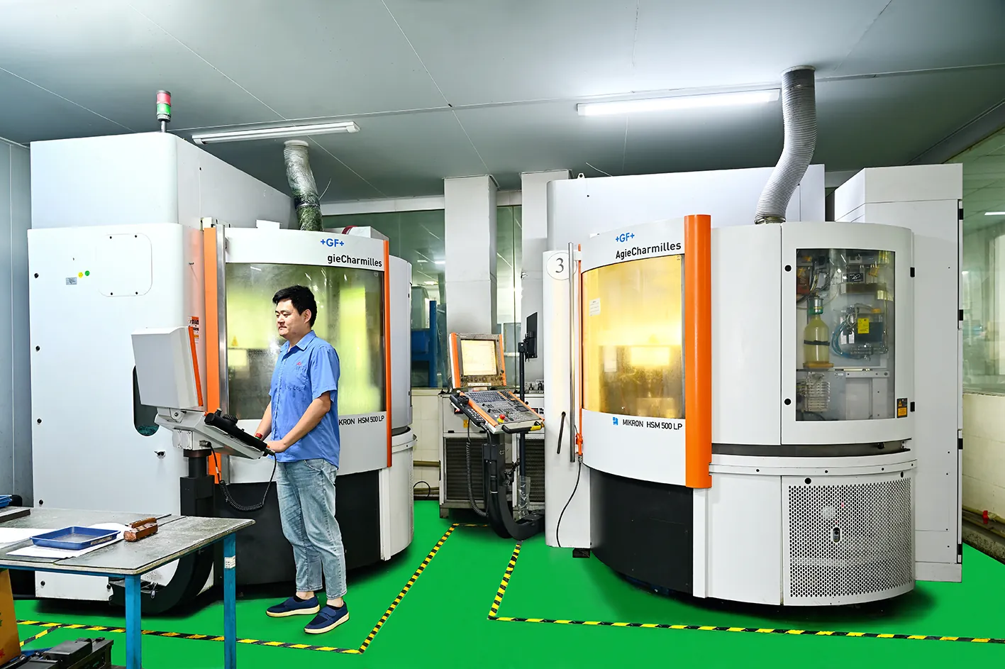
Surface finish is where the direction choice is most visible, because every tooth leaves its fingerprint. Climb finishing shears each chip from maximum to zero thickness and exits clean, so the machined surface carries uniform feed scallops and no burnish zone. Conventional finishing leaves feed marks overlaid on the rubbed entry zone, plus a larger exit burr at every pass end. The table below gives typical Ra bands for the same tooling and comparable parameters; the spread is the direction, not the tool.
| Strategy | Typical Ra | Exit burr | Work-hardening risk | Typical use |
|---|---|---|---|---|
| Climb finishing | 0.4-0.8 µm | Minimal | Low | Cavity finish, hardened steel, thin walls |
| Conventional finishing | 0.8-1.6 µm | Larger | High (entry rubbing) | Scale pass aftermath, backlash-limited machines |
| Climb roughing | 1.6-3.2 µm | Low | Low | Volume removal, trochoidal paths |
| Conventional roughing | 3.2-6.3 µm | Moderate | Moderate | First pass on scale, cast, or oxide skin |
← swipe to scroll →
Ra bands assume coated carbide, comparable parameters, and a rigid machine. Runout below 0.003 mm at the tool tip is required to hold Ra 0.4 µm; at 0.005 mm runout the practical floor rises to roughly 0.8 µm.
Three factors sit under these numbers. Runout first: at HRC 50 and above, tool system runout matters more than any other variable — a tool at 0.010 mm runout finishes at Ra 1.6 µm where the same path at 0.003 mm holds Ra 0.4 µm. Second, stepover: ball-nose finishing at 0.05-0.15 mm stepover with a controlled scallop height of 0.01 mm or less is what makes a finish pass actually finish. Third, the milled surface feeds the next operation: a climb-finished cavity at Ra 0.4-0.8 µm goes to polish, while an EDM-finished surface typically arrives at Ra 0.4-1.6 µm with a recast layer that must be removed before polishing — the comparison that decides when wire EDM beats milling and when it does not. Texture grades applied later, such as VDI 27-36, sit on top of the machined finish, so the machined surface underneath still sets the polishing baseline.
Tool Wear and Tool Life
Tool wear patterns reveal the milling direction in a worn tool the way a police report reveals an accident. Conventional milling concentrates wear at the entry zone of the cutting edge, because that is where the tooth rubs before the chip builds; the same edge wears faster and hotter, and the rubbing heat accelerates flank wear. Climb milling loads the edge uniformly from entry to exit on clean stock, producing even flank wear and longer, more predictable edge life. The table below maps the common failure modes to each direction.
| Failure mode | Climb milling | Conventional milling | Prevention |
|---|---|---|---|
| Flank wear | Uniform along the edge, slower on clean stock | Concentrated at entry; rubbing accelerates it | Climb on machined surfaces; keep chip load above the minimum |
| Edge chipping | Entry impact on scale or hard skin at full chip thickness | Exit shock at maximum chip thickness; interrupted edges | Conventional scale pass first; tough edge prep; small radial engagement |
| Built-up edge | Less likely (clean shear) | More likely (rubbing plus heat) | Higher SFM, coolant at the edge, sharp edge prep |
| Chatter and grab | Requires backlash-free, rigid machine | Self-stabilizing on loose machines | Preloaded screws, rigid fixture, small radial engagement |
← swipe to scroll →
Direction interacts with tool geometry, coating, and machine condition; the table shows the dominant tendency of each direction, not a law.
The practical result is that climb finishing on clean mold steel commonly returns 20-40% longer edge life than conventional finishing at the same parameters — a typical shop-floor observation rather than a guaranteed figure, because tool, machine, and coating shift the number. Two edge cases matter for mold work. First, the scale pass: a conventional first pass that breaks the skin protects every climb pass that follows, so the total tool spend across the job is lowest when the directions are sequenced, not argued. Second, chipped edges: when an edge does chip and the tool leaves a mark or a damaged surface in a cavity, the fix is bench repair — weld, re-machine, re-polish — which is the workflow covered in our how to repair a damaged mold guide. Scheduled tool inspection between finishing passes catches the chipping trend before it becomes a cavity defect.
How Mold Shops Actually Choose
No mold shop sets milling direction once per job; it sets it per operation, per machine, per stock condition. The sequence below is the one DieStrike runs, and it is a reasonable template for any shop: decide by audit, not by habit.
- Machine audit: check backlash, spindle condition, and rigidity. Backlash present or spindle bearings worn — conventional for any cut that can grab; preloaded ball screws and linear guides — climb is available.
- Stock audit: inspect the block for scale, cast skin, or oxide. Present — one conventional pass to break the skin, then climb for everything after.
- Material and hardness audit: steel grade and actual HRC. Above roughly 45 HRC, finishing is climb-only; below that, direction is free.
- Geometry audit: thin walls, thin floors, interrupted features, deep pockets. Thin walls and floors finish climb; interrupted cuts get the entry-impact review.
- Operation audit: roughing, semi-finishing, or finishing. Trochoidal and dynamic roughing are climb; scale passes are conventional; finishing on clean stock is climb.
- Parameter set: SFM, chip load, radial and axial engagement, stepover, then direction confirmed against the audits — not picked first.
- Verification: first-article Ra by profilometer, critical features on the CMM, and tool wear inspection at scheduled intervals before the finish pass.
| Situation | Direction | Why |
|---|---|---|
| Finishing pass on machined mold steel | Climb | Clean shear, typical Ra 0.4-0.8 µm, minimal burr |
| First pass on scale, cast, or oxide skin | Conventional | Zero-thickness entry protects the edge from the hard layer |
| Machine with backlash (manual mill, worn CNC) | Conventional | Force opposes the feed and keeps the screw loaded |
| Thin wall or thin floor finishing | Climb | Downward force holds the wall; less deflection and chatter |
| Hardened steel at 46-52 HRC finishing | Climb | No rubbing phase; work hardening avoided; edge survives |
| Interrupted cuts across holes or slots | Conventional, or climb at low engagement | Progressive entry absorbs repeated impact events |
| Trochoidal and dynamic roughing | Climb | Constant small radial engagement, constant chip load |
← swipe to scroll →
Direction is decided per operation after auditing machine, stock, hardness, and geometry — never as a blanket shop rule.
The workflow ties back to decisions made long before the toolpath: draft angles, corner radii, and texture choices set which surfaces get a fine climb finish and which get bench work, which is why direction planning belongs inside the mold design considerations review. And because direction errors surface as Ra misses and taper, the verification step is where the process closes the loop — the measurement discipline for critical features is the same one we use to hold 0.002 mm positions, covered in our how to hold 0.002 mm precision mold tolerances guide.
Frequently Asked Questions
Q1. Which is better for mold machining: climb or conventional milling?
Climb milling for finishing passes on clean machined mold steel: better surface finish (typically Ra 0.4-0.8 µm versus 0.8-1.6 µm), less burr, no entry rubbing, and it is the only practical choice above roughly 45 HRC. Conventional milling for scaly or oxide-covered stock, machines with backlash, and some interrupted cuts. A mold shop uses both; it sequences them.
Q2. Why does climb milling produce a better surface finish?
Each tooth enters at maximum chip thickness and exits at zero, so every chip is sheared cleanly with no rubbing phase and no exit burr. Conventional milling enters at zero chip thickness, rubs and burnishes the surface before the chip builds, carries chips back over the cutter to be re-cut, and exits at maximum chip thickness, pushing material out into a burr.
Q3. Why is climb milling risky on scaly or cast surfaces?
The tooth engages the hard scale at maximum chip thickness — a full-impact load against an abrasive layer on every tooth. The edge chips and the tool fails quickly. Conventional milling enters at zero chip thickness, loads progressively, and shears under the scale. Standard practice: one conventional pass to break the skin, then climb for everything after.
Q4. Can I climb mill on a manual mill or an older CNC?
Only if the axis has no measurable backlash. Climb milling pulls the work into the cutter, and with leadscrew or ball-screw backlash the table lurches forward into a deeper bite — chatter, grab, and tool breakage. Conventional milling pushes against the feed and keeps the screw flank loaded, which is why it remains the safe default on loose machines.
Q5. Does milling direction change tool life?
Yes. On clean stock, climb milling wears the edge uniformly and typically returns 20-40% longer edge life on finishing passes than conventional milling at the same parameters. Conventional milling concentrates wear at the entry zone where the tooth rubs, and the rubbing accelerates flank wear and built-up edge. The exception is scale: climb on a scaly surface chips the edge almost immediately.
Q6. What speeds and feeds should I start with for P20 and hardened H13 or S136?
For a 12 mm coated carbide end mill: P20 at 28-34 HRC roughs at 300-450 SFM and 0.06-0.10 mm/tooth, finishes at 400-550 SFM and 0.03-0.05 mm/tooth. Hardened H13 and S136 at 46-52 HRC finish at 200-350 SFM and 0.01-0.03 mm/tooth with a 0.05-0.15 mm stepover. These are starting points — validate against your tool supplier, machine rigidity, and coolant.
Q7. Does climb milling reduce thin-wall deflection?
Yes. Climb milling's vertical cutting force component pushes the wall down into the block, holding it; conventional milling lifts the wall away from the cutter, deflecting it and producing taper and chatter. Thin cavity ribs at 0.5-2 mm are finished climb at low radial engagement for exactly this reason.
Q8. Should roughing and finishing use different milling directions?
Often, yes. The classic sequence is conventional roughing on a scaly block to break the skin, then climb for semi-finishing and finishing. On modern rigid machines, trochoidal or dynamic roughing is climb by design. The direction is set per operation after auditing the machine, the stock, and the geometry — not as one blanket setting.
The Bottom Line
Climb milling is the default for finishing on clean machined mold steel — better Ra, less burr, no work hardening, and the only practical direction on hardened cavities above 45 HRC. Conventional milling is a precision tool, not a compromise: it protects the edge on scale and oxide, stabilizes machines with backlash, and absorbs interrupted-cut shock. The mold shop's job is to sequence the two correctly per operation, which is a machining-plan decision made before steel is cut, not a preference discovered after the first tool fails.
DieStrike audits machine, stock, and geometry before programming, runs a 24-hour mold design DFM review that flags finishing risks before steel is cut, and manufactures the cavity with climb finishing and profilometer verification as standard practice on every injection mold manufacturing project. Send us your part and mold steel — we will return a machining plan with the direction decisions made, and a quote you can hold us to. Contact DieStrike with your drawing.
KEEP READING
Related Reading
Injection Mold Manufacturing Process: From Drawing to Trial in 7 Steps
Every injection mold follows the same sequence: DFM review, mold design and flow analysis, steel order, rough…
Read articleArticlePrecision CNC Machining for Mold Components
Precision CNC machining for mold components: tolerance classes from ±0.005 mm standard to ±0.002 mm critical and 0.
Read articleArticleWire EDM for Mold Making: Accuracy, Surface, and Cost
Wire EDM machining for mold making with real numbers: ±0.002 mm accuracy grades, Ra 0.2–0.
Read articleArticle5 Mold Cooling Channel Design Tips for Faster Cycles
Mold maker's 5 cooling channel design rules: channel-to-cavity distance 2-2.
Read articleNEXT STEP
Ready to Start Your Mold?
Send us your element dimensions or part numbers — our team responds within 24 hours with pricing and lead time.

Written by
Ray ChanMold Buyer's Guide Author · Precision Mold Manufacturing Specialist. Ray helps global importers, distributors and OEMs source factory-direct molds and mold parts.