
Precision CNC Machining for Mold Components
Table of Contents
Machined to the drawing, a mold component is invisible: it sits inside a tool that nobody sees and produces parts that everybody inspects. Miss it by 0.02 mm and the failure becomes public. A cavity insert seat machined 0.02 mm oversize lets the insert shift under injection pressure; the cavity wall thins by the same 0.02 mm, wall-thickness variation shows up on the molded part, and assembly rejects a batch that cost four figures to run. The machining was cheap. The tolerance was the product.
This guide covers precision CNC machining for mold components the way buyers need it: tolerance classes and what each one costs to hold, prehardened versus hardened steel machining, high speed machining that finishes cavities at Ra 0.4 µm, when to hand off to jig grinding or EDM, and how CMM verification closes the loop before the component ships. It is written for engineers who buy molds and for manufacturing engineers who have to make the numbers survive contact with a 120-machine floor.
The Snapshot
Precision CNC machining for mold components, in numbers
- Standard DieStrike tolerance for machined mold components is ±0.005 mm; critical fits run ±0.002 mm, and jig grinding finishes to 0.0005 mm (0.5 µm).
- Cavity surfaces typically finish at Ra 0.4-0.8 µm straight off the CNC; sinker EDM can reach Ra 0.02 µm for polish-ready texture.
- Prehardened steels (P20 at 28-32 HRC, 718 at 33-38 HRC) machine with standard carbide; hardened steels at 48-52 HRC need coated carbide, light cuts and high speed machining.
- High speed machining on 15,000-30,000 rpm spindles with shallow axial cuts of 0.05-0.3 mm is how hardened cavities are roughed and finished without heat-treat distortion.
- CMM full inspection with typical published uncertainty of ±0.001-0.002 mm per axis is standard on critical components — not an add-on.
- A cooling line that breaks through a 2 mm cavity wall is a scrapped mold; tolerance allocation on the drawing decides which features stay on the CNC and which move to EDM or grinding.
Why Mold Components Demand Machine Precision
A mold is an assembly of components — cavity and core inserts, guide pins, ejector pins, cooling inserts, gate inserts — and every one of them is a precision machined part with its own drawing, its own tolerance and its own failure mode. The mold itself is not inspected at the end of a production line; it is inspected by the parts it makes, every single shot. That is why cnc machining tolerance on mold components is a production decision, not a drawing nicety.
The risk chain runs through four failure classes. Assembly failure: an insert seat cut loose, a guide pin bore off by 0.01 mm, and the mold halves no longer register — parting line mismatch and gating misalignment. Dimensional drift: the cavity is the mold of the part, so every micron of cavity error becomes part error — 0.02 mm on a 0.8 mm connector wall is a press-fit failure. Hidden geometry: a cooling line that breaks through a thin wall, an ejector bore that exits through the forming surface — defects no part measurement will ever reveal. Process instability: loose components shift under the 400-800 bar pressures typical of molding, so a mold that assembled fine runs differently every cycle.
None of this shows up in a cheap quote; it shows up in the first 500 shots, when a mold with loose components starts flashing or sorting itself into scrap. The parts that carry these risks — inserts, pins, slides — are covered by custom mold insert machining and the injection mold manufacturing process that assembles them. Precision is not the premium option; it is the only option that keeps a mold out of these failure classes.
The Precision Chain: Machine, Tooling, Measurement
Precision CNC machining is a chain of three links — the machine, the tooling, and the measurement that verifies both. Break any one and the tolerance leaks, usually in a direction nobody notices until the component is in service.
Machine. A precision machining center holds its ±0.002 mm positioning only in a thermally stable environment. Steel grows about 11.5 µm per meter per degree Celsius (typical published expansion coefficient), so a 200 mm insert drifts roughly 0.0023 mm per degree of shop temperature change. Shops that hold micron-level work run the floor near 20 °C, let machines reach thermal equilibrium before critical jobs, and qualify positioning against a laser interferometer on a schedule. The machine list matters less than the maintenance log — the same discipline covers the Mikron high-speed machining centers on our 120+ machine floor.
Tooling. The cutter is where most precision is lost. Tool runout, holder stiffness, and tool deflection all write themselves into the machined surface. Shrink-fit or hydraulic holders beat collets for runout on finishing passes; a tool held with 0.01 mm runout machines 0.01 mm oversize features and leaves scalloped finishes. Deflection grows with the cube of stick-out, which is why deep, thin-wall pockets are finished with short, stiff tools or handed to EDM. Carbide with TiAlN or AlTiN coatings is standard for mold steels; uncoated HSS has no place in a hardened cavity.
Measurement. The loop closes on measurement, which has its own accuracy budget. In-process probing catches drift mid-job; the final word comes from a CMM in a temperature-controlled gauge room at 20 ± 1 °C, with typical published uncertainty of ±0.001-0.002 mm per axis. A shop that measures critical dimensions with a caliper at the machine has not decided what its tolerance actually is. The full measurement-to-trial sequence is in our guide to holding ±0.002 mm.
Tolerance Classes for Mold Components
Tolerance is a budget, and the first step in precision CNC machining is assigning the budget per feature instead of stamping one number on the whole drawing. Most mold components do not need ±0.002 mm everywhere — most need it somewhere, and the drawing should say where. A useful way to think in classes:
| Tolerance Class | Typical Features | Process That Holds It | Verification |
|---|---|---|---|
| ±0.01 mm (IT7-IT8) | Mold base plates, non-critical pockets, clearance bores, mounting features | Standard CNC milling and drilling; no secondary operations | Calipers and micrometers, spot checks |
| ±0.005 mm (IT6) | Insert profiles, bore positions, ejector pin holes — the standard DieStrike mold component tolerance | CNC machining with probing, finishing passes, precision grinding on mating faces | CMM sampling on critical features |
| ±0.002 mm (IT5) | Guide pin alignment, core/cavity mating diameters, insert-to-insert shut-offs, gating inserts | Jig grinding, wire EDM with trim passes, hardened-state finishing | CMM full check of all critical dimensions |
| 0.0005 mm (0.5 µm) increments | Final ODs, IDs, shoulders and concentricity on pins, bushings and shut-off diameters | Jig grinding and optical profile grinding after heat treatment | CMM and air gauging at 20 ± 1 °C |
← swipe to scroll →
Reference frame: at 10-18 mm basic size, ISO 286-1 IT5 equals 4 µm and IT6 equals 6 µm total tolerance — a ±0.002 mm feature is a 4 µm window. Typical published values; assign per feature, not per drawing.
Each step down the ladder multiplies cost and lead time: tighter tolerances need better machines, secondary operations and full CMM verification. That is why DieStrike assigns classes during the free 24-hour DFM review — if a feature does not need ±0.005 mm, we say so on the first pass. Asking "which tolerance, on which feature" separates a machining plan from a quoting exercise.
Machining Mold Steels: Prehardened vs Hardened
Mold component machining splits into two regimes: machining prehardened steel in the supplier condition, or machining steel after hardening. The choice is a distortion decision as much as a cutting decision.
Prehardened machining cuts the steel at its delivered hardness — P20 at 28-32 HRC, 718 (P20 + nickel) at 33-38 HRC — with standard carbide, fast material removal and no heat treatment afterward. The advantage is speed and geometry stability: the part is machined once, to final size, and nothing moves later. The limitation is final hardness — a prehardened P20 insert tops out near 30-32 HRC, fine for low-to-medium volume tools but quick to wear on abrasive resins. Prehardened machining is the default for most cavity and core work.
Hardened machining cuts the component after hardening — H13, S136 or tool steel at 44-52 HRC, with 48-52 HRC the typical finishing band. Machining after hardening eliminates heat-treatment distortion and decarburization on finished surfaces, because the final geometry is cut into the final hardness. The cost is cutting difficulty: coated carbide or CBN tooling, high speed machining with light cuts, far slower material removal. The payoff is a component whose dimensions never moved in the furnace — which is why shut-off faces, guide surfaces and high-wear features are routinely finished after hardening.
| Material | Machining Condition | Typical Hardness | Machining Approach |
|---|---|---|---|
| P20 (1.2311) | Prehardened | 28-32 HRC | Standard carbide, high material removal for roughing, conventional 3D finishing; general-purpose cavity steel |
| 718 (1.2738, P20 + Ni) | Prehardened | 33-38 HRC | Carbide with modest speed reduction; better through-hardness for larger inserts and thick sections |
| H13 (1.2344) | Annealed, then hardened | 44-52 HRC after hardening | Rough in annealed condition, harden, then finish machine at 48-52 HRC; hot-work grade for die-casting and high-heat molds |
| S136 (1.2083 / 420 SS) | Prehardened or hardened | 30-52 HRC | Corrosion-resistant; cut with sharp positive-geometry carbide, finish polished for optical and medical surfaces |
| Tool steel (e.g. SKD61 / D2) | Hardened | 48-52 HRC typical finishing band | TiAlN/AlTiN coated carbide or CBN, high speed machining with 0.05-0.3 mm axial cuts, jig grinding for final fits |
← swipe to scroll →
Typical published hardness bands; supplier certificates state the actual delivered value per heat. Full grade comparisons in our P20 vs H13 vs S136 guide.
The practical rule: if a component must survive abrasive flow or high clamp pressure, plan hardened steel machining for the critical features; if it must be cheap and dimensionally quiet, prehardened machining serves. State the delivered condition on the drawing — hardness range and machining state — because a supplier cannot quote a process for an undefined hardness.
High Speed Machining Strategies
High speed machining (HSM) is the workhorse of precision CNC machining for mold components once the steel is hardened. It inverts conventional cutting logic: instead of deep cuts at moderate speed, HSM takes shallow cuts at high spindle speed and feed with light radial engagement, so cutting forces stay low and heat stays in the chip.
The parameters that matter, with typical published ranges: spindle speeds of 15,000-30,000 rpm (Mikron machines on our floor run in this band); axial depths of cut of 0.05-0.3 mm for finishing hardened steel; radial engagement held to roughly 5-10% of tool diameter; ball-nose end mills from Ø6 mm down to Ø0.5 mm for 3D cavity work. Roughing runs trochoidal or peel-milling paths that keep engagement constant, so the tool never loads up in a corner — load spikes that break cutters are a programming choice, not a material property. Cutting speed for hardened steel finishing with coated carbide typically lands around 60-120 m/min.
Surface finish is where the strategy pays. A well-run HSM finishing pass on a hardened cavity typically lands at Ra 0.4 µm, with Ra 0.8 µm a comfortable production standard — a short polishing step from a glossy texture. Scallop height is set by stepover, not luck: constant-scallop paths adjust it to curvature, so a steep wall and a flat floor finish to the same Ra.
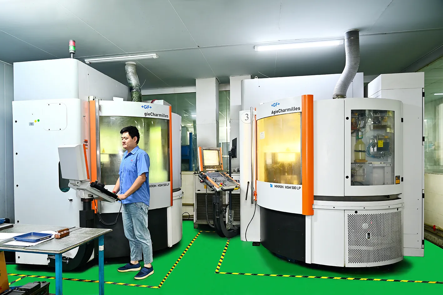
Three rules keep HSM honest. Machine stiffness beats spindle speed: a rigid frame at 20,000 rpm holds tolerance better than a flexible one at 30,000 rpm. Tool condition is everything: a worn ball-nose leaves finish bands and pushes deflection into the wall, so finishing cutters are replaced on a schedule. And HSM feeds the secondary operations rather than replacing them — corners tighter than the smallest practical cutter and deep ribs move on to EDM or grinding.
Jig Grinding and Final Finishing
When a mold component needs geometry that a milling cutter cannot deliver — a Ø10 mm bore with 0.002 mm roundness, a shut-off diameter ground after hardening, concentricity between an OD and an ID that both matter — the final word goes to jig grinding. A jig grinder locates the wheel spindle precisely in X and Y and grinds holes, ODs, shoulders and tapers in hardened steel with positioning to 0.0005 mm (0.5 µm) — a full decimal tighter than CNC milling's practical ±0.002 mm. Our floor runs Waida jig grinders in exactly this role: the finishing operation for guide diameters, insert bores and pin features that carry the mold's alignment.
Wheels run at high peripheral speed — typically 20,000-60,000 rpm equivalent — with light passes and frequent dressing, because the wheel geometry writes itself into the hole. The process is slow on purpose: a jig-ground bore is measured between passes, and the last few microns come off in passes of a couple of micrometers each. That is why ±0.002 mm mating diameters are quoted with jig grinding time, and why the table above routes IT5-class features here.
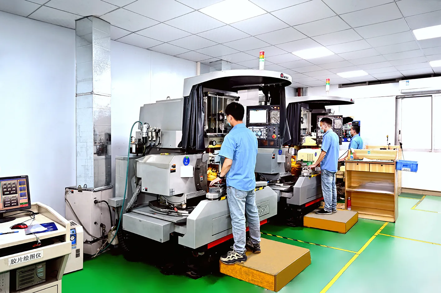
Optical profile grinding (Wasino machines on our floor) is the companion process: the operator projects a magnified profile of the part against a scaled drawing and grinds the form to the projected outline — the standard method for punches, form tools and complex outer profiles. Together, jig grinding and optical grinding fill the gap between CNC milling and EDM: 0.0005 mm positioning and mirror-like bearing surfaces become routine on hardened components.
CNC vs EDM for Mold Details
Every mold has features a milling cutter cannot produce economically — routing a feature to EDM instead of CNC is a geometry decision, not a capability judgment. Three features decide it: internal corner radius, depth-to-diameter ratio, and sharp detail.
Internal corners. A milling cutter leaves a radius wherever it turns: an Ø1 mm end mill leaves a 0.5 mm inside corner, and going smaller trades productivity for deflection. Practical CNC machining tolerance on small internal corners bottoms out around R0.1-0.3 mm with tiny, fragile cutters. Sinker EDM burns a corner limited by the electrode's edge — R0.05 mm or sharper is routine, and sharp inside corners are an EDM signature. If the drawing calls a sharp internal corner at the bottom of a deep rib, CNC is the wrong process for that feature.
Deep cavities. Milling a slot or rib with a length-to-diameter ratio beyond roughly 5:1 invites deflection, chatter and broken cutters — the tool wanders, and the wander writes itself into the wall. EDM has no cutting force, so a 20:1 aspect-ratio rib is routine: the electrode and the spark do the work. Cooling channels, deep ribbing between cores and thin deep slots are classic sinker EDM territory on a mold whose open surfaces were machined on the CNC.
The trade-offs. EDM's cost is surface integrity: the spark leaves a recast white layer typically 0.005-0.05 mm thick (typical published values) that must be accounted for or removed — trim passes and fine finishing reduce it, and polish-ready surfaces are EDM'd at fine settings first. Wire EDM positions to ±0.002 mm and is the standard method for through-profiles on hardened inserts. Sodick sinker and wire machines on our floor handle this work, with super-fine finishing down to Ra 0.02 µm — the grade referenced in our mold manufacturing process guide.
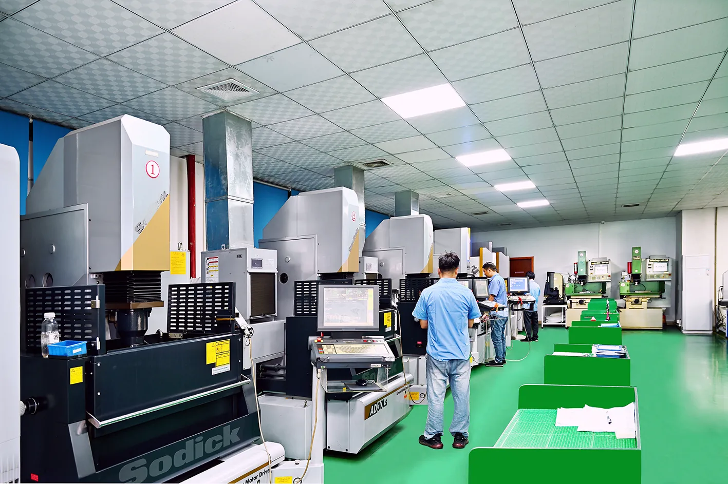
The strongest mold shops run the two processes as one system: CNC machines the open geometry, EDM finishes the corners and depths, jig grinding closes the tolerances. The drawing should say which features are which — a feature drawn as a sharp corner but quoted as CNC milling will not meet the drawing.
Verification: CMM and Measurement Reports
Precision CNC machining without verification is an opinion. The final link is measurement: for mold components, CMM full inspection on critical dimensions in a temperature-controlled gauge room. Typical published CMM uncertainty runs ±0.001-0.002 mm per axis on machines verified to ISO 10360 — the same order as the tolerances being checked — hence the 20 ± 1 °C gauge room and no hand tools on critical measurements.

What a useful report contains: nominal versus measured value per critical dimension, deviation, tolerance and pass/fail; true position, profile and concentricity for GD&T call-outs; and the drawing revision verified. Under IATF 16949 programs — our plant is certified — the report is part of the PPAP trail, with lot-level traceability from material certificate through machining, heat treatment and inspection. Ask for a sample report before you order, not after a failure.
Sampling strategy matters as much as the machine. Components at ±0.005 mm are typically verified by CMM sampling on critical features; ±0.002 mm features are verified 100%, because one out-of-tolerance guide pin bore fails an assembly, not a statistic. State the measurement plan on the RFQ — who measures what, with what instrument, at what temperature. A component is not finished when it leaves the machine; it is finished when the report says the drawing was met.
How to Write Machining Requirements on Your RFQ
Most tolerance disputes start on the RFQ, not the machine. A drawing without a tolerance strategy invites the supplier to guess, and the guess is usually the cheapest process route. Write the machining requirements the way a shop floor can execute them, and the quotes you get back will compare apples to apples. The checklist:
- Send STEP or native CAD plus a 2D drawing with GD&T per ASME Y14.5 or ISO 1101 — datums first, then true position and profile instead of bare coordinate ±, so the tolerance zone is unambiguous.
- State the material grade and the delivered condition: prehardened P20 at 28-32 HRC, hardened 48-52 HRC, or annealed-then-hardened — the process route changes with the hardness band.
- Call surface finish with an Ra value and where it applies: Ra 0.8 µm functional, Ra 0.4 µm HSM finishing, polish-to-gloss steps named separately.
- Mark the process-critical features explicitly: sharp internal corners, deep ribs and thin slots that need EDM; diameters and concentricity that need jig grinding after hardening.
- Specify edge breaks, deburring and surface treatment — a missing chamfer call-out is a rework order waiting to happen.
- State the verification and documentation package: CMM full check versus sampling, material certificates, and the measurement report format required for PPAP or your own incoming inspection.
- Name the tolerance class per feature, not one blanket number — and let the supplier challenge features that do not need the tight class; that challenge is a DFM conversation, not a negotiation.
DieStrike runs a free 24-hour DFM review on every inquiry — tolerance classes assigned per feature, process routes named, firm quotation with lead time. Our mold design and DFM service covers the review side, and the mold manufacturer selection guide explains how to read the quotes you get back. A clear RFQ is the cheapest precision investment in the program.
Frequently Asked Questions
Q1. What tolerance can precision CNC machining hold on mold components?
±0.005 mm is a realistic CNC production standard; ±0.002 mm on critical fits requires grinding, wire EDM trim passes or hardened-state finishing; jig grinding reaches 0.0005 mm (0.5 µm). Assign the class per feature — each step down multiplies process time.
Q2. Should mold components be machined prehardened or after hardening?
Prehardened machining (P20 at 28-32 HRC, 718 at 33-38 HRC) is faster and dimensionally quiet — no heat treatment after cutting. Hardened machining (48-52 HRC) cuts final geometry into final hardness, eliminating distortion and decarb, at the cost of slower cutting with coated carbide or CBN. High-wear and alignment features are routinely finished after hardening.
Q3. How is Ra 0.4 µm achieved on a machined cavity?
With high speed machining: 15,000-30,000 rpm spindles, axial cuts of 0.05-0.3 mm, radial engagement at 5-10% of tool diameter, ball-nose tooling with constant-scallop paths and sharp coated carbide. Ra 0.8 µm is a comfortable production standard; Ra 0.4 µm is routine finishing; lower Ra means polishing or super-fine EDM.
Q4. When should a mold detail be EDM instead of CNC machined?
When a milling cutter cannot reach the geometry: internal corners sharper than roughly R0.1-0.3 mm, cavities or ribs past about a 5:1 depth-to-diameter ratio, sharp details at depth. EDM has no cutting force, so 20:1 ribs are routine — at the cost of a recast layer that must be accounted for.
Q5. What documentation should ship with precision machined mold components?
Material certificates (EN 10204 3.1) with heat number, a CMM report with nominal-versus-measured values and pass/fail per critical dimension, and heat treatment logs for hardened components. Under IATF 16949, lot-level traceability is a requirement — agree the report format before ordering.
Q6. What is a realistic lead time for precision machined mold components?
DieStrike quotes complete molds at 2-5 weeks depending on size and complexity; individual precision machined components typically ship faster, and the 24-hour DFM review fixes the route and schedule on day one. Hardened components with jig grinding and full CMM verification carry the longer end of the bracket.
The Bottom Line
A tolerance lost in machining becomes flash, wall-thickness drift and assembly failure — and it usually surfaces only in production. DieStrike runs the full chain on one floor: 120+ machines, Mikron high speed CNC, jig grinding to 0.0005 mm, and CMM full inspection on every critical component.
KEEP READING
Related Reading
Climb vs Conventional Milling: Mold Shop Choice
Climb milling cuts from maximum chip thickness down to zero; conventional milling cuts from zero up to maximum.
Read articleArticleInjection Mold Manufacturing Process: From Drawing to Trial in 7 Steps
Every injection mold follows the same sequence: DFM review, mold design and flow analysis, steel order, rough…
Read articleArticleWire EDM for Mold Making: Accuracy, Surface, and Cost
Wire EDM machining for mold making with real numbers: ±0.002 mm accuracy grades, Ra 0.2–0.
Read articleArticle5 Mold Cooling Channel Design Tips for Faster Cycles
Mold maker's 5 cooling channel design rules: channel-to-cavity distance 2-2.
Read articleNEXT STEP
Ready to Start Your Mold?
Send us your element dimensions or part numbers — our team responds within 24 hours with pricing and lead time.

Written by
Ray ChanMold Buyer's Guide Author · Precision Mold Manufacturing Specialist. Ray helps global importers, distributors and OEMs source factory-direct molds and mold parts.