
Injection Mold Manufacturing Process: From Drawing to Trial in 7 Steps
Table of Contents
A buyer approves a mold order and then hears nothing for three weeks. On week four, the shop sends a photo of a mold base — still untouched, still waiting for inserts. The parts ship a month late, the production launch slides, and the tool that should have paid for itself in six months starts its life in arrears. This is the cost of buying a process you cannot see.
Every injection mold follows the same seven-step sequence: DFM review, steel order, rough machining, finish machining, assembly, trial, and approval. The sequence is not a suggestion — it is the critical path of a precision asset, and each step has a measurable duration and a deliverable. Knowing the sequence lets you track progress, spot delays early, and ask the right question at the right milestone.
This guide walks through every step of the injection mold manufacturing process as DieStrike runs it, from the part file arriving to the CMM report shipping with the finished tool. Each step names what happens, how long it typically takes, and what you should receive at the end of it.
The Snapshot
- The full sequence runs DFM → design → steel → rough machining → finish machining → heat treatment → assembly → trial → approval, with plastic molds quoted at 2-4 weeks total.
- The DFM review is step zero and the cheapest correction point: DieStrike returns it free within 24 hours.
- Finish machining holds ±0.005mm standard and ±0.002mm critical features with wire EDM, jig grinding, and high-speed CNC on 120+ in-house machines.
- Production cavities are hardened to HRC 62, and every mold ships with CMM reports, material certificates, and heat treatment logs under IATF 16949.
- Know the milestones: design freeze, steel arrival, machining start, assembly, T0, T1. A shop that cannot name its milestones cannot track its schedule.
The Seven-Step Process at a Glance
The table below is the master schedule every mold follows. Durations are typical ranges for a mid-size production mold and vary with size, cavity count, and steel grade — but the sequence never varies, because every step depends on the one before it.
| Step | What Happens | Typical Duration | Deliverable |
|---|---|---|---|
| 1. DFM review | Part analysis, mold layout, cavity count, gate plan | 24 hours | DFM report with cost-impact flags |
| 2. Mold design | 3D design, mold flow analysis, cooling layout | 2-4 days | Design freeze, drawing revision locked |
| 3. Steel order and base | Material certs, standard base procurement | 2-5 days | EN 10204 3.1 material certificates |
| 4. Rough machining | CNC roughing of plates and inserts | 3-7 days | Pocketed inserts, stress-relieved steel |
| 5. Finish machining | Wire EDM, jig grinding, high-speed detail work | 5-10 days | Features at ±0.005mm, ±0.002mm critical |
| 6. Heat treatment and finishing | Vacuum hardening to HRC 62, coatings, polishing | 2-5 days | Hardness logs, SPI finish per surface |
| 7. Assembly | Fitting ejector system, cooling, guides, mechanisms | 3-6 days | Assembled mold, bench checks passed |
| 8. Mold trial (T0/T1) | Sampling on supervised trial presses, defect correction | 2-5 days | Trial samples, defect record |
| 9. Approval and delivery | CMM report, samples, documentation pack | 1-2 days | Approved mold with full documentation |
← swipe to scroll →
Typical durations for a mid-size production mold; your schedule depends on size, cavity count, and steel grade. Confirm milestones with your supplier.
Add the steps together and the range lands inside DieStrike's quoted 2-4 week lead time for plastic molds. The steps overlap where the schedule allows — steel is ordered while design finalizes, and polishing begins on one insert while another is still on the wire EDM. What never overlaps is the sequence of dependencies: you cannot trial a mold that has not been assembled, and you cannot assemble inserts that have not been machined.
Step 1: DFM Review — The Step That Saves the Most Money
The DFM review analyzes the part file before any steel is cut: parting line, gate position, draft angles, wall balance, shrink compensation, and ejection strategy. Its purpose is to find every problem that would otherwise surface as rework weeks later — and to find it while the only cost of a change is a keystroke.
This is the cheapest correction point in the entire process. A design flaw caught in DFM costs nothing and costs a day. The same flaw caught after steel cutting costs machining hours, new steel, and schedule — typically 30-50% added to the final tooling bill (typical industry estimate). The DFM step is free at DieStrike and non-negotiable for a smooth build, with feedback returned within 24 hours of receiving the file.
A serious DFM review does more than approve the drawing. It flags every tight tolerance with its cost impact, confirms achievable limits against the shop's real machining standard (±0.005mm, with ±0.002mm on critical features), and recommends the cavity count, steel grade, and gate plan the part actually needs. That is scope locked before the price — which is exactly why our mold quote guide tells you to read the scope line before the price line.
Send the drawing, the material spec, and the volume plan together. One unambiguous input produces one comparable DFM. Our RFQ guide lists every field a complete request should carry, and the mold design and DFM service page details what the review returns.
Step 2: Mold Design and Mold Flow Analysis
Once the DFM is approved, the mold is designed in 3D: plate stack, cavity layout, runner and gating, cooling circuit, and ejection system. The design freeze locks the drawing revision, and from that moment every change is a change order with a price. Freezing the revision before the quote is approved is the single most effective schedule protection a buyer has.
Mold flow analysis runs in parallel on critical parts. The analysis simulates fill, pressure, temperature, and weld lines before the steel is ordered, and it catches the defects that trials would otherwise find at the end of the schedule: short shots from a bad gate location, warpage from uneven cooling, trapped air from a missing vent. DieStrike runs mold flow analysis on hot runner systems and complex geometries as standard — see the hot runner systems page for how the analysis drives manifold and nozzle selection.
Cooling design belongs to this step, not to the shop floor. Cooling channel placement decides cycle time and part quality, and the layout must be drawn before machining starts because channels are drilled into the steel. Our cooling channel design guide covers the geometry rules — and the consequences of skipping them: uneven cooling that warps parts and extends cycle time on every shot the mold ever takes.
At the end of design you should receive the design freeze confirmation and the locked drawing revision. If a shop starts machining before you confirm the design, you have already lost control of the schedule and the scope.
Step 3: Steel Selection and Ordering
Steel is ordered with material certificates after the DFM sign-off. The grade was chosen in the DFM: P20 for general production, H13 for high-temperature resins and high cycle counts, S136 for transparent or corrosive applications. The full trade-off is in our P20 vs H13 vs S136 guide; the important process point is that the grade decision happens before ordering, not during machining.
The mold base is a standard series (HASCO, DME, or MISUMI) unless the part demands custom plates. Standard bases carry catalog prices, ship faster, and are replaceable anywhere in the world — our mold bases page shows the series DieStrike builds to, and our mold base specification guide covers the selection rules. A custom base costs 30-50% more and adds lead time, so it should be a documented decision, not a default.
Material traceability starts here. Every block arrives with a mill test certificate (EN 10204 3.1), and the certificate follows the steel through machining, heat treatment, and assembly into the final documentation pack. Under IATF 16949, that traceability is a requirement, not a favor — automotive buyers should confirm the certificate trail at this step, not at delivery.
Step 4: Rough Machining
Rough machining removes the bulk of the steel. CNC machining centers pocket the plates and inserts, cutting the cavity envelope, core outlines, and mounting features. The goal at this step is speed with controlled stress: heavy cuts remove material fast, and the steel is often stress-relieved or normalized before or after roughing so the finish machining does not chase a moving target.
Rough machining on the DieStrike floor runs on high-speed machining centers and gantry machines — part of the 120+ machine fleet documented on our about page. The roughing strategy matters for two reasons. First, it sets the stock condition for the finish work: too little stock and the finish pass has nothing to true up; too much and the finish machines burn hours. Second, it is where most of the "wasted" machining time lives or dies — a shop that roughs smart is a shop that finishes on schedule.
Deliverable at this step: pocketed inserts and plates with the cavity envelope established and the steel in a stable condition. This is also the first visible proof of progress — a buyer who asks for a machining progress photo at this milestone is asking a fair question.

Step 5: Finish Machining — CNC, Wire EDM, Jig Grinding
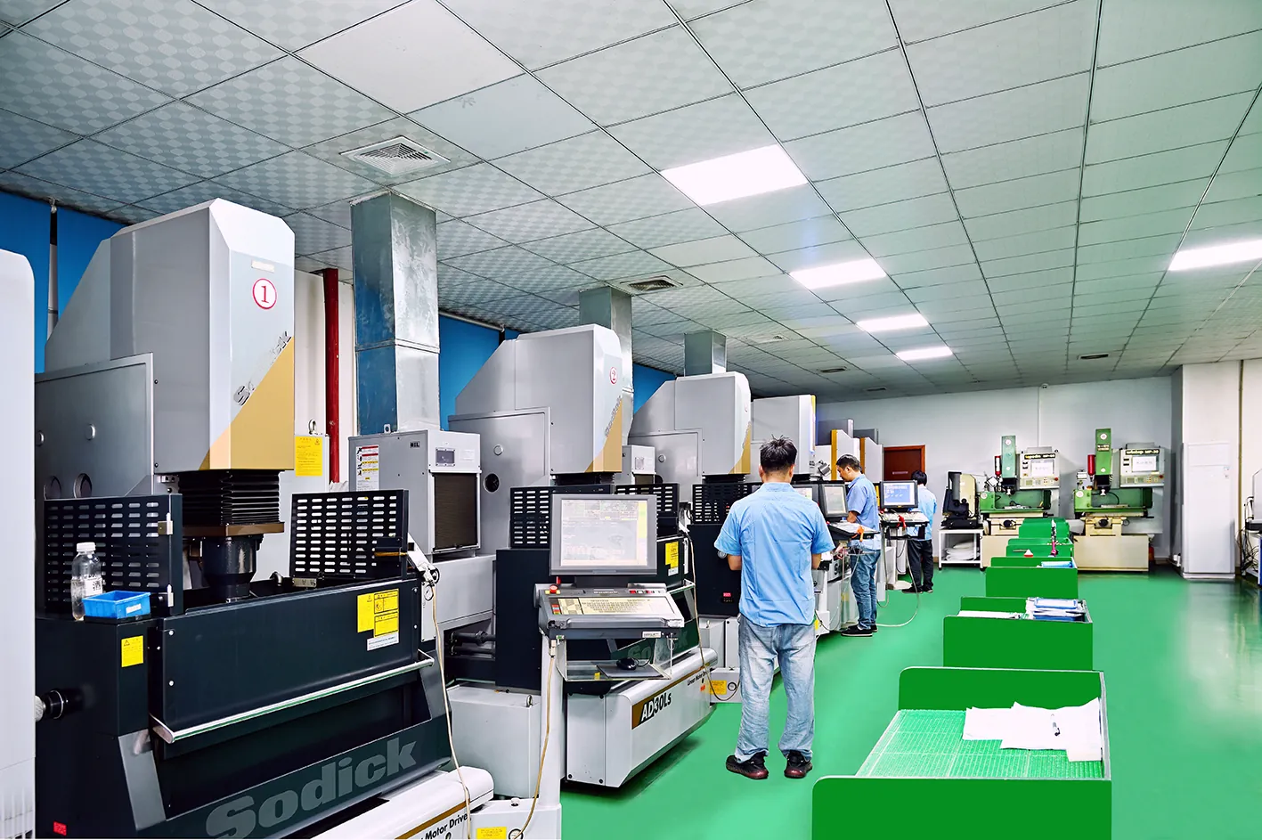
Finish machining brings the features to tolerance, and it is where precision claims live or die. This is the step where DieStrike holds ±0.005mm standard and ±0.002mm for critical features, using the machines the tolerance demands:
- High-speed CNC for deep cavities, thin walls, and complex cores with ±0.005mm positioning accuracy.
- Wire EDM for punch and insert profiles, shut-off details, and tight internal corners, holding ±0.002mm with taper and trim passes.
- Jig grinding for the hardest tolerances — 0.0005mm capability for matched bore-and-pin sets and critical diameters.
- Mirror EDM for fine surface finishes in hard-to-reach geometry where cutting tools cannot reach.
Each process has a cost profile, and the tolerance plan decides the mix. A feature at ±0.005mm runs on standard finish milling. The same feature at ±0.002mm moves to wire EDM or jig grinding, and the machining time roughly doubles (typical practice). Moving it to ±0.001mm can double again. Our ±0.002mm tolerance guide explains which features genuinely need the slow machines — and which are paying for capability they do not use.
The machining order matters as much as the machines. DieStrike hardens the cavity block first, then finish-machines and polishes to final geometry. That sequence holds mold part geometry to ±0.002mm and overall mold accuracy to ±0.005mm. Hardening after finish machining risks distortion, and grinding away a hardened skin removes exactly the wear resistance you paid for — the sequence is a quality decision, not a convenience.
Step 6: Heat Treatment and Surface Finishing
Heat treatment converts the machined steel into a wear-resistant tool. DieStrike vacuum-hardens production cavities to HRC 62 for critical inserts, with typical hardness ranges of HRC 48-56 for standard cavity steel and up to HRC 62 for SKD61/H13 ESR grades. Vacuum heat treatment keeps decarburization and distortion under control — the hardness is achieved without losing the geometry the finish machining just cut.
The heat treatment order was set in the previous step: harden first, then finish-machine and polish. That sequence preserves the hardened skin at the surface where wear happens. Hardening after finish machining risks distortion, and grinding away the hardened case removes the wear resistance. The process log should record the target hardness range, not a single number — a target of HRC 50-54 differs from HRC 56-60 in wear and grindability.
Surface finishing runs alongside: coatings for wear resistance and polishing for appearance and release. Nitriding and PVD coatings extend insert life on abrasive and glass-filled materials, typically by 2-4x (published range). Polishing takes surfaces to the specified SPI grade, from B1 through A2 mirror — and mirror finishes at Ra 0.02 are achievable on the DieStrike floor for optical and cosmetic parts.
Deliverable at this step: hardness logs per insert, coating records, and the polished surfaces per the SPI callouts on the drawing. If the drawing says SPI A-1 and the shop cannot show a polishing process that reaches it, that gap will surface at trial — as a rejected part.
Step 7: Assembly and Polishing
Assembly fits the finished components into the base: the ejector system, cooling connections, guide pillars, and any slides, lifters, or unscrewing mechanisms. Bench assembly ends with checks that matter: guide-post alignment to the base, ejector travel and return, shut-off contact, and cooling circuit leak testing. Every check is a verification step, not a formality — a mold that fails an assembly check would fail the trial more expensively.
Ejector systems deserve their own attention at this step. Ejector pins, core pins, sleeves, and springs are fitted with the clearances the part needs, and the pin grades were chosen in design for the wear they will see. DieStrike manufactures standard ejector pins in SKD61 and SKD11 with HASCO/DME/MISUMI interchangeability and mirror finishes at Ra 0.2 — see the ejector pins page for the range, and our core pin vs ejector pin guide for when each is the right choice.
Polishing continues into assembly on assembled surfaces where the fit affects the finish. The final polish pass happens after fitting, because assembly can mark surfaces, and a marked mirror surface will show on every molded part. This is also where texture is applied if the part carries a cosmetic texture spec.
At the end of assembly you should receive: bench check records, cooling circuit verification, and the mold ready for its first trial. If a shop skips straight from machining to trial with no assembly check, the trial becomes the assembly check — and trial time is billed.
Step 8: Mold Trial — T0 and T1 Sampling
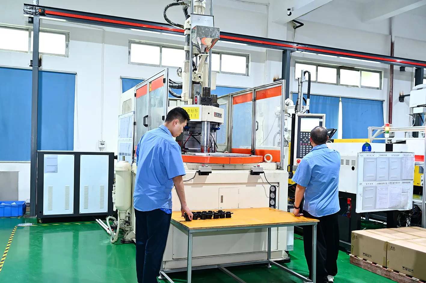
The mold is mounted on an injection trial press and sampled. T0 verifies fill, ejection, and basic function — the mold closes, fills, cools, and ejects without damage. Corrections are made; T1 validates critical dimensions against the drawing with CMM measurement. Structured trial milestones with written defect records separate professional toolmakers from shoot-and-hope operations.
The trial step is where the process quality shows. A shop with dedicated trial access — like DieStrike’s T1 sampling service — can correct, re-trial, and confirm within days instead of weeks, because press time, machinists and inspectors are coordinated on one schedule. A shop that outsources trials adds shipping, queue time, and communication gaps to every trial round.
Set the acceptance criteria before the trial, not during it: dimensions on the drawing, surface finish grade, and a shot count without defects. Written criteria turn the trial into a pass-fail event instead of a debate. Typical quotes include 1-3 trial rounds (typical practice), and extra rounds are billed — one more reason the DFM step matters.
Step 9: Approval and Documentation
Final approval includes the CMM dimensional report, steel certificates, heat treatment logs, trial samples, and maintenance documentation. The mold ships as a documented, reproducible asset — not just steel. Under IATF 16949, the documentation pack is part of the deliverable: lot-level traceability, material certificates (EN 10204 3.1), and T0-T2 trial reports follow the tool through its life.
For automotive programs, PPAP documentation is available at Levels 1-3. The report line belongs in the quote scope — read our mold quote guide for what a complete report list looks like — because documentation is real work with real cost, and it is not free just because you assumed it was included.
Inspection closes the loop: the vision-measuring and CMM equipment that verified the inserts during machining verifies the finished mold at approval. The dimensional report should carry measured points for every critical dimension — a report that says "within tolerance" without points is a note, not evidence.
How to Track Progress and Spot Delays
You cannot manage a schedule you cannot see. Ask your supplier for milestone dates at kickoff, and check progress against the grid below. Each milestone has a normal sign and a red flag — the same discipline our quote-reading guide applies to the price lines applies here to the schedule.
| Milestone | Normal Sign | Red Flag |
|---|---|---|
| DFM and quote | Feedback within 24 hours, scope itemized | No written DFM, vague scope |
| Design freeze | Drawing revision locked and confirmed | Machining starts before you confirm design |
| Steel and base | Material certs shared, standard base ordered | No certificate trail, unnamed base source |
| Machining start | Progress photos of pocketed inserts | No visible work after week one |
| Assembly | Bench check records, cooling tested | Assembly skipped or undocumented |
| T0/T1 trial | Trial report with defect record and fixes | No written trial criteria or report |
| Approval | CMM report, certs, samples, docs shipped | Tool ships with no documentation |
← swipe to scroll →
Typical practice markers. Confirm the milestone list with your supplier before the PO.
Ask what the clock starts on. If it starts when you sign, that is clean. If it starts after design approval, add your own two weeks to the number. And ask for the schedule behind the lead time — a shop that gives one number with no milestones is quoting hope, not a plan.
Frequently Asked Questions
Q1. How long does it take to manufacture an injection mold?
DieStrike quotes plastic molds in 2-4 weeks and stamping dies in 2-5 weeks, with a 24-hour DFM review before the price locks. Within that window, the schedule breaks into design, steel, machining, heat treatment, assembly, and trial — ask for the milestone dates, not just the ship date.
Q2. What is the difference between T0 and T1 trials?
T0 verifies fill, ejection, and basic function — the mold works as a mechanism. T1 validates critical dimensions against the drawing with CMM measurement after corrections. Some programs add T2 for fine-tuning cycle time and cosmetics. Each round should produce a written defect record with the fix applied.
Q3. Why is the DFM review so important?
Because it is the cheapest correction point in the process. A design flaw caught in DFM costs nothing; the same flaw caught after steel cutting can add 30-50% to the tooling bill (typical industry estimate). The DFM review at DieStrike is free and returns within 24 hours.
Q4. Which tolerances can an injection mold realistically hold?
DieStrike holds ±0.005mm as the standard machining tolerance and ±0.002mm on critical features, with jig grinding capability to 0.0005mm. The tolerance plan decides which machines run and how long — read the tolerance line as a cost curve, not a checkbox.
Q5. What documents should ship with a finished mold?
A CMM dimensional report with measured points, material certificates (EN 10204 3.1), heat treatment logs, T0-T2 trial reports, and maintenance documentation. Automotive programs can add PPAP Levels 1-3 under the IATF 16949 quality system. If the quote does not list the report pack, ask for it before you sign.
Q6. What causes mold manufacturing delays?
The most common causes are scope changes after the design freeze, revision mismatches on the drawing, and trial rounds that keep failing because the DFM was skipped. Each one is preventable: lock the revision, freeze the scope, and treat the DFM as the first milestone rather than an optional favor.
The Bottom Line
The injection mold manufacturing process is a sequence of nine steps with a deliverable at each one — DFM, design, steel, rough machining, finish machining, heat treatment, assembly, trial, and approval. Buyers who track the milestones get their molds on schedule and in tolerance. Buyers who track only the ship date find out what went wrong after the parts are late.
Start with the step that saves the most: send your part file to DieStrike's engineering team for a free DFM review and get feedback within 24 hours. Then follow the milestones in this guide — and ask for each deliverable as it lands.
KEEP READING
Related Reading
Climb vs Conventional Milling: Mold Shop Choice
Climb milling cuts from maximum chip thickness down to zero; conventional milling cuts from zero up to maximum.
Read articleArticlePrecision CNC Machining for Mold Components
Precision CNC machining for mold components: tolerance classes from ±0.005 mm standard to ±0.002 mm critical and 0.
Read articleArticleWire EDM for Mold Making: Accuracy, Surface, and Cost
Wire EDM machining for mold making with real numbers: ±0.002 mm accuracy grades, Ra 0.2–0.
Read articleArticle5 Mold Cooling Channel Design Tips for Faster Cycles
Mold maker's 5 cooling channel design rules: channel-to-cavity distance 2-2.
Read articleNEXT STEP
Ready to Start Your Mold?
Send us your element dimensions or part numbers — our team responds within 24 hours with pricing and lead time.

Written by
Ray ChanMold Buyer's Guide Author · Precision Mold Manufacturing Specialist. Ray helps global importers, distributors and OEMs source factory-direct molds and mold parts.