
How to Repair a Damaged Mold: 7-Step Workflow
Table of Contents
At 22:50, on the changeover shift, an operator spotted a hairline crack running 12 mm along the gate landing of a 32-cavity connector mold. The crack ran 0.3 mm wide at the mouth, deep enough to catch a fingernail. The press cycled 40 more shots before anyone stopped it.
The estimate ladder was ugly. A weld and recut ran $900 with a 3-day lead time. A replacement insert ran $4,200 with a 10-day lead time. A new mold ran $58,000 with a 4-week lead time. Meanwhile the idle press burned $150 per hour and the customer's line held a $40,000 order.
Most mold damage is discovered the same way: late, at a shift boundary, with the press down and a delivery date on the line. In a 500,000-cycle tool life, the average mold sees two to four unplanned damage events. The repair itself is usually straightforward. The expensive part is the decision between weld, insert, recut, and replace, made under time pressure without data. This guide walks the seven-step workflow DieStrike's repair shop runs, from dye check to dimensional sign-off, with the numbers that make every call.
Every step has a pass or fail threshold. Step 1 proves the damage. Step 2 prices the options. Steps 3 to 6 execute the repair. Step 7 proves the mold is back to print.
Run the workflow in order and a $2,000 weld repair stays $2,000. Skip the assessment and weld over a live crack, and the same repair becomes a $4,200 insert, or a $58,000 mold.
The Snapshot
- A dye penetrant check catches surface cracks as narrow as 0.01-0.02 mm after a 15-30 minute dwell.
- A TIG weld repair on P20 or H13 runs $200-$2,500 with a 2-5 day lead time (typical industry figures).
- H13 needs preheat at 300-400°C before welding and a double temper after, to hold 44-52 HRC.
- A replacement cavity insert runs $800-$8,000 with a 7-15 day lead time, against DieStrike's ±0.005 mm mold precision.
- The trial after repair runs 50-200 shots and closes with a CMM report on every critical dimension.
How Molds Get Damaged
Damage in production tooling has five origins: thermal fatigue, mechanical overload, erosion, corrosion, and mishandling. Most molds record their first reportable damage before 100,000 cycles. Each failure leaves a signature, and the signature decides the repair method. Read the damage before you price the fix, because the wrong read is the expensive step.
Thermal Fatigue Cracks
Cavity steel heats and cools every cycle, and surface temperature past 300°C starts the fatigue clock. Uncoated tool steel develops heat checking after 500-1,000 cycles, a network of fine cracks 0.05-0.3 mm deep. Each cycle extends them. A 0.1 mm heat check on a gate landing grows to 0.5 mm in roughly 50,000 cycles under a 200°C melt-to-steel delta. Dye check finds them, and crack depth decides whether welding or an insert is cheaper.
Mechanical Damage
Dropped inserts, jammed ejectors, and crushed shutoffs leave dents, nicks, and gouges. A 0.5 mm nick on a parting line flashes on every shot, and a crushed shutoff work-hardens and grows with each cycle. Impact damage on a solid cavity face usually welds cleanly, because the base steel stays sound. Impact that bends a thin core under 3 mm wall thickness usually means a new insert, because straightening leaves residual stress and a latent crack.
Corrosion and Erosion
Water leaks, condensate, and chlorides above 50 ppm pit unprotected steel. P20 pits within weeks of exposure. S136, with roughly 13% chromium, resists the same water for years.
Erosion is the mirror image: melt flowing past a gate wears the land, and glass-filled resin accelerates it. A gate land that grows 0.1 mm shifts the pressure drop and triggers a recut. Corrosion pits 0.05-0.2 mm deep weld and repolish cleanly, but only after the leak that caused them is fixed.
Step 1: Assess the Damage Before You Touch a Wrench
The assessment answers four questions: where the damage starts, how deep it goes, whether the steel underneath is sound, and what the surrounding geometry requires. Budget 2-4 hours of bench time for a single cavity. At $100-$400 per assessment (typical industry figure), that is 5% or less of the cheapest repair, and it prevents doing the same repair twice.
Dye Penetrant Check
Clean the suspect area with solvent, apply red or fluorescent penetrant, and let it dwell 15-30 minutes. Wipe the surface, apply developer, and read the bleed-out. Visible dye resolves cracks 0.01-0.02 mm wide and finer. Fluorescent dye under UV is the standard for critical tooling. Every weld repair starts with a dye check, because welding over an uncleaned crack simply moves it deeper.

Crack Depth and Sound Steel
A surface crack may stop at 0.1 mm or run 5 mm into the wall. Measure depth by ultrasonic testing or by progressive grinding, taking 0.1-0.2 mm passes and re-dyeing until the crack disappears. The weld rule: remove the crack completely plus 2-3 mm of sound steel around it. Keep the remaining wall above 50% of the original thickness. A through-wall crack, or a wall below that, takes welding off the table.
CMM and 3D Scan
Set the mold on the CMM, align to the datums on the drawing, and record the damaged region. A CMM resolves 0.001-0.003 mm, enough to prove whether the surrounding geometry moved during the damage event. A 3D scan adds speed at ±0.02-0.05 mm typical accuracy, and it is the fastest route to reverse-engineer a broken insert. Compare the scan to the CAD model and the T1 measurements before ordering steel. DieStrike holds mold size precision at ±0.005 mm and part geometry at ±0.002 mm, so the assessment standard matches the build standard.

Photograph Everything
Photograph the damage from the same angle before, during, and after the repair, with a scale reference in frame. The photos go into the mold book next to the CMM data. Insurance claims, customer disputes, and warranty reviews are decided by the before image, not the memory of it. A repair without a photo record is a repair you cannot prove.
Step 2: Choose the Repair Method
Four methods cover nearly every mold damage case, and the price spread between them runs from $200 to $80,000. The decision is a cost and risk calculation, not a preference. Run the matrix below, then read the notes for your damage type.
| Damage Type | Repair Method | Cost Range | Lead Time | Key Risk |
|---|---|---|---|---|
| Hairline crack in cavity corner, depth under 50% of wall | Weld + recut | $200-$2,500 | 2-5 days | Hardness mismatch, distortion |
| Through-wall crack or broken rib | New insert | $800-$8,000 | 7-15 days | Fit-up, cooling line mismatch |
| Galled or eroded parting line | Weld or recut | $300-$2,000 | 2-7 days | Vent depth change, flash |
| Corrosion pitting on cavity face | Weld + re-polish or recut | $400-$2,200 | 3-7 days | Recurrence if the leak is not fixed |
| Worn or damaged ejector pin bore | Sleeve or new insert | $500-$3,000 | 4-10 days | Pin fit class loss |
| Cracked mold base plate | New base or mold replacement | $10,000-$80,000 | 2-5 weeks | Full part requalification |
← swipe to scroll →
Table: typical industry figures; verify against your program.
The matrix numbers are typical industry figures, and mold size, steel grade, and cavity count move them. DieStrike's mold repair and maintenance service quotes each case with a fixed price and lead time before work starts.
When Welding Wins
Weld first when the base steel is sound, the crack is fully removable, and a polishing stone can reach the surface. Nicks, gate erosion, parting line damage, and shallow heat checking all weld well. P20 welds the easiest of the common grades, with a modest 150-250°C preheat. The weld zone must end within 2-3 HRC of the base hardness. Otherwise the patch wears faster than the surrounding steel and becomes the next failure point.
When a New Insert Wins
Choose an insert when the crack passes through the wall, or when the damage sits under a corner EDM cannot reach. Choose it too when the steel is already on its second or third weld. A new custom mold insert runs $800-$8,000 with a 7-15 day lead time (typical industry figures). It costs more than a weld and less than a mold, and it resets the wear budget to zero. DieStrike machines inserts to the same ±0.005 mm mold precision as the original cavity.
When Recut or Replace Wins
Recut when the damage is a worn land, an oversized vent, or a shallow gouge that machining removes within drawing tolerance. A recut runs $300-$2,000 and takes 2-7 days. Replace the mold when the base plates are cracked, or when the damage repeats after two weld repairs. Replace it when the repair estimate passes 50-60% of a new tool. A new injection mold from DieStrike runs 2-4 weeks, a stamping die 2-5 weeks, and both requalify the part from scratch.
Step 3: Weld the Tool Steel
Welding tool steel is a heat management problem. Get the preheat, filler, and post-weld cycle right and the patch is invisible in service. Get any one wrong and the weld zone cracks, softens, or distorts. The steel grade sets every number. DieStrike builds cavity inserts hardened to HRC 62, so the repair must return the steel to the drawing hardness, not a round number.
Preparation and Preheat
Grind the crack out to a 60-degree included angle V-groove with a radiused root, then clean with acetone. No sharp root, no burnt edges, no oil. Preheat before the first arc: P20 at 150-250°C, H13 at 300-400°C, S136 at 200-300°C. Confirm with a contact thermometer or temperature crayon, not the feel of the steel. Preheat slows the cooling rate in the heat-affected zone, which prevents hardening cracks in H13 and soft zones in P20.
Filler Selection
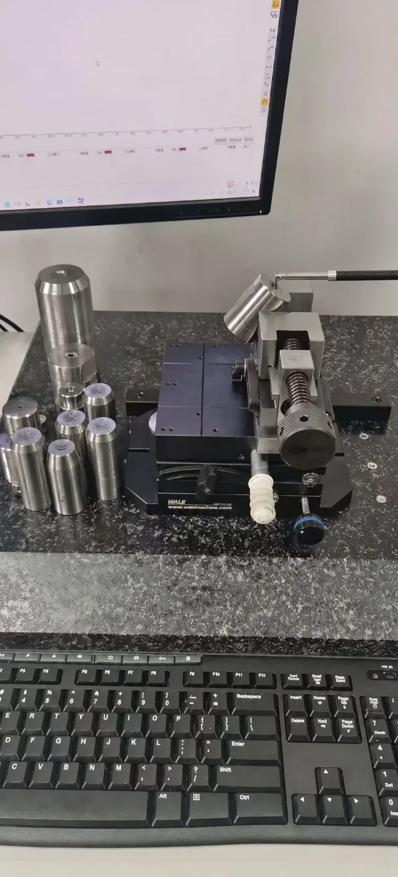
Match the filler to the base steel, not to the catalog. P20 welds with a P20-type filler and lands back at 28-32 HRC with modest post-weld treatment. H13 takes an H13 or SKD61 filler, holds 44-52 HRC after tempering, and survives mold surface temperatures past 500°C.
S136 takes a 420-type stainless filler, keeps its corrosion resistance, and is the right call when the cavity runs water-side or with corrosive resin. A mild steel rod on an H13 cavity creates a soft patch that wears out in 10,000-20,000 cycles. For the full grade comparison, see P20 vs H13 vs S136.
Welding Technique
TIG weld with argon shielding at 8-12 L/min, and keep stringer beads short, 20-40 mm, so each bead cools before the next. Interpass temperature stays at or below the preheat window: 300°C max for P20, 400°C max for H13. Peen each bead lightly with a needle scaler to counter shrinkage stress, and grind between passes to remove oxide. One long continuous bead concentrates shrinkage at the ends and pulls the cavity wall.
Post-Weld Stress Relief and Hardness Recovery
The weld zone and its heat-affected zone need a stress relief cycle before the cavity returns to service. P20 stress-relieves at 550-600°C with a slow furnace cool. H13 needs a full double temper at 540-620°C to restore 44-52 HRC. Skip it and the HAZ sits 3-8 HRC soft and cracks under the next thermal cycle.
S136 stress-relieves at 200-300°C to hold its 48-52 HRC and its corrosion layer. After the cycle, check hardness on the weld, the HAZ, and the base: all three must sit within 2-3 HRC of each other. Then dye check the weld again. A crack that appears after stress relief is a preheat failure. It is cheaper to find that crack on the bench than in the press.
| Steel Grade | Typical Hardness | Filler Match | Preheat | Post-Weld Cycle | Target Hardness |
|---|---|---|---|---|---|
| P20 (1.2311) | 28-32 HRC | P20-type filler | 150-250°C | Stress relief 550-600°C, slow cool | 28-32 HRC |
| H13 (1.2344) | 44-52 HRC | H13 / SKD61 filler | 300-400°C | Double temper 540-620°C | 44-52 HRC |
| S136 (420 stainless) | 48-52 HRC | S136 / 420-type filler | 200-300°C | Low-temp stress relief 200-300°C | 48-52 HRC |
← swipe to scroll →
Table: typical industry figures; verify against your program.
Step 4: Machine and EDM the Geometry Back
The weld has to come back to geometry before it comes back to surface. Rough machining removes the bulk of the weld, EDM cuts the corners and text, and the finish pass leaves the stock that polishing removes. DieStrike's repair shop holds the same ±0.005 mm mold precision on repairs as on new builds.
Machining the Weld
Mill the weld down to within 0.1-0.3 mm of final geometry with a ball-nose end mill, keeping stepover under 0.5 mm on the finish pass. Leave stock, never cut below the line: a cavity cut 0.05 mm under spec needs a second weld to fix. Machine with coolant on steel above 45 HRC, and read chip color as a heat signal.
EDM for Corners and Text
EDM reaches what the cutter cannot: sharp internal corners, deep ribs, and engraved text. Sinker EDM with a graphite or copper electrode holds ±0.005-0.01 mm, and wire EDM cuts through-wall features. Finish with a low-amperage trim pass so the surface lands at Ra 0.8-1.6 µm before polishing. The white layer left by EDM, the recast skin, runs 0.005-0.03 mm thick and is hard, brittle, and cracked. Remove it by polishing or light machining, because a recast layer in a gate area spalls off in service.

Verify Before You Polish
Take the cavity back to the CMM and check every critical dimension against the drawing before polishing starts. Polishing removes material, and a cavity already 0.01 mm under size should stop here. This is the last gate where geometry can still be corrected cheaply.
Step 5: Restore the Polish and Texture
The part surface copies the cavity surface, so the finish of the repair is the finish of the part. Match the surrounding area, never polish to a nice-looking finish. A gate area runs SPI A-2 at Ra 0.025-0.05 µm, while a cosmetic surface runs SPI B-3 at Ra 0.4-0.8 µm (typical industry values).
The Polish Sequence
Work through abrasive grits from 400 to 600 to 800 to 1000, then diamond paste at 3 µm and 1 µm. Verify with a profilometer, not by eye. The weld zone stays slightly softer right after stress relief. It polishes faster than the base and can dish out 0.005-0.02 mm if you linger.
Texture Restoration
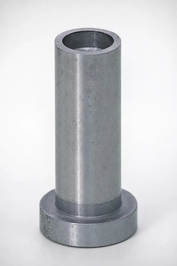
Weld repair removes texture, and matching texture means chemical etching. Mask the polished lands, etch the repair area in 5-30 minute cycles, and compare against the adjacent texture with a silicone replica at 10-20x. Standard mold texture etch depth runs 0.02-0.05 mm (typical). A photo-etched pattern only matches reliably through the supplier's etching film.
Edge Protection
Protect the edges where texture meets polished land with 0.05-0.1 mm radii. Sharp texture edges wear first and collect flash, and the same rule applies to vent edges after recutting.
Step 6: Check Fitting and Venting
A repaired cavity has to fit the mold before it can mold parts. Two checks matter: shutoff contact against the mating half, and venting at the parting line. A shutoff must show 70-80% contact after a blue check, and vent depth must hold 0.02-0.05 mm per the resin spec. Both are measured, never eyeballed.
Blue Check and Shutoffs
Coat the mating face with Prussian blue, close the mold, and open it. The repaired area must show 70-80% contact across the shutoff. A low spot on a repaired shutoff becomes flash at 0.02-0.05 mm. Correct low spots by spotting and stoning, and re-check until the contact patch is even.
Venting
Recut the vents to the depth the resin calls for, typically 0.02-0.05 mm with a 1-3 mm land (typical industry values). Verify depth with a depth gauge or a wax cast. A vent too deep flashes at the parting line. A vent left clogged by the repair burns the part edge in a few hundred shots.
Ejectors and Slides
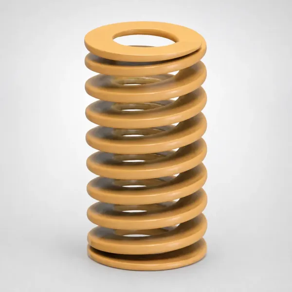
Check every ejector pin returns flush with the repaired face within ±0.02 mm. Pin clearance must stay at 0.01-0.02 mm for pins up to Ø12 mm. Check slides re-seat with 0.02-0.05 mm clearance and a full lubrication pass. A repaired cavity with a dragging pin fails in the first 1,000 cycles, and that failure undoes the repair. Replacement pins and springs ship in 3-7 days from DieStrike's standard parts line, so the fix never waits on inventory.
Step 7: Trial and Dimensional Verification
The repair is done when the part is done. The trial run proves the mold, and the dimensional report proves the part. A 50-200 shot trial and a clean CMM report close the file. The same verification standard applies to molds DieStrike repairs for TE Connectivity, Amphenol, Luxshare, and Dongshan Precision.
The Trial Run
Run 50-200 shots through the repaired mold and inspect the first parts at 5-10 shot intervals. Check for flash at the repaired shutoff, gate blush, and drag marks on the repaired surface. Burn marks or short shots on thin sections mean the venting is still wrong. Press conditions stay at the T1 record during the trial, so the only variable is the repair.
The Dimensional Report
Measure the trial parts on the CMM against the drawing and the T1 record. Critical dimensions must hold drawing tolerance, typically ±0.05 mm for connector parts, and DieStrike's standard is ±0.002 mm on part geometry. A part 0.03 mm over nominal on the repaired feature is a geometry miss, not a pass. Release the mold only when the report is clean.
Update the Mold Book
File the dye check photos, the weld record, the hardness readings, and the trial report in the mold book. The next damage event on this mold gets priced faster and fixed cheaper because the record exists. If the damage repeats, the trend is the evidence to replace the mold, not repair it again.
FAQ: Mold Repair
Q1. Can a cracked mold cavity be welded?
Yes, when the crack is fully removed and the remaining wall stays above 50% of the original thickness. P20 welds with a 150-250°C preheat. H13 needs 300-400°C and a double temper after. The finished weld zone must land within 2-3 HRC of the base hardness.
Q2. How much does mold repair cost?
A weld repair runs $200-$2,500, a recut $300-$2,000, a new insert $800-$8,000, and a full mold $10,000-$80,000 (typical industry figures). The assessment adds $100-$400 in bench time before any work starts.
Q3. How long does a mold repair take?
A weld repair takes 2-5 days, a recut 2-7 days, a new insert 7-15 days, and a full replacement mold 2-5 weeks. Press downtime runs $120-$250 per hour while you wait (typical industry figure).
Q4. When should I replace the mold instead of repairing it?
Replace when the base plate is cracked, or when the crack passes through the wall. Replace when the same damage repeats after two weld repairs. Replace when the estimate passes 50-60% of a new tool. A repair that repeats is a design or grade problem, not a welding problem.
Q5. Does welding damage the mold steel?
Welding creates a heat-affected zone that sits 3-8 HRC soft without post-weld treatment. Preheat, controlled interpass temperature, and a stress relief or temper cycle restore the hardness, and the finished weld must match the base within 2-3 HRC.
The Final Call
A damaged mold is a decision, not a disaster. A weld at $200-$2,500 beats an insert at $800-$8,000. An insert beats a new mold at $58,000. Both only hold with an honest assessment and a correct weld cycle. DieStrike repairs under IATF 16949 across 120+ machines, holding ±0.005 mm mold precision.
Send us your part drawing for a repair assessment with DFM feedback within 24 hours, plus selection advice and a cost breakdown within 48 hours.
KEEP READING
Related Reading
5 Mold Cooling Channel Design Tips for Faster Cycles
Mold maker's 5 cooling channel design rules: channel-to-cavity distance 2-2.
Read articleArticle5 Shrinkage Compensation Rules for Mold Design
Shrinkage compensation decides mold accuracy. Five rules: material rates from 0.3% to 2.
Read articleArticle5 Ways to Reduce Mold Cost Without Cutting Quality
Five proven ways to reduce injection mold cost without cutting quality: DFM before quoting, right-sized cavity count,…
Read articleArticle7 Gate Design Best Practices for Balanced Filling
Mold maker's 7 gate design rules for balanced multi-cavity filling: gate depth 50-80% of wall thickness, land 0.5-1.
Read articleNEXT STEP
Ready to Start Your Mold?
Send us your element dimensions or part numbers — our team responds within 24 hours with pricing and lead time.

Written by
Ray ChanMold Buyer's Guide Author · Precision Mold Manufacturing Specialist. Ray helps global importers, distributors and OEMs source factory-direct molds and mold parts.