
Hard Milling vs EDM for Mold Finishing: How to Choose
Table of Contents
At the buy-off of a 32-cavity connector mold, the customer flagged a 0.008 mm EDM white layer on a shut-off edge. After 12,000 cycles the re-melted skin spalled, opened a 0.02 mm gap, and every shot flashed. The shop had burned the whole cavity because two internal corners needed a 0.05 mm radius. Route selection, not machine accuracy, caused the failure.
Hard milling and sinker EDM both finish hardened cavity steel after heat treatment. They leave different corner radii, different surfaces, and very different hours on the floor. This guide compares the two routes for mold finishing and gives buyers a feature-by-feature way to choose. Production bands below are typical industry values from tooling catalogs, EDM suppliers, and published machining sources.
Most cavity details can be cut either way. The deciding variables are internal corner radius, feature depth and reach, surface integrity, and total cost per finished surface. A buyer who specifies those four items in the RFQ stops paying for rework and trial shots.
The Snapshot
- Hard milling finishes open geometry in 48-62 HRC steel with coated carbide or cBN ball-nose tools at 0.05-0.2 mm stepovers.
- A ball-nose cutter leaves an internal corner equal to its own radius, 0.1-0.3 mm typical. A dressed electrode burns 0.03-0.1 mm corners.
- Sinker EDM leaves a white layer of 0.002-0.015 mm typical, removed by polishing away 0.01-0.03 mm or a low-current finish burn before plating or texture.
- Electrode wear runs 0.1-1% per burn typical, so critical cavities use one rough and one finish electrode at a spark gap of 0.01-0.05 mm.
- Machine hours cost about $70-130 for a CNC milling cell and $90-170 for sinker EDM with electrode prep, typical U.S. ranges.
The snapshot numbers set the frame. The rest of this guide assigns each number to a feature. A quoting engineer can then route a cavity in minutes instead of betting a program on habit.
The Finishing Decision After Roughing
Roughing removes the bulk of the steel and leaves 0.3-0.8 mm of stock on cavity walls and floors. Most cavity blocks rough in annealed or pre-hardened steel at 30-48 HRC, then harden to 48-62 HRC. Finishing after hardening makes every dimension the molded part touches, so it happens in the hard state. The route choice comes before the first finishing tool touches the block.
Heat treatment is why finishing comes last. A vacuum-hardened block can distort roughly 0.05-0.2% of its length, so a 200 mm cavity plate can move 0.1-0.4 mm out of position. Grinding and finish machining recover the datum, then the shop cuts or burns the detail. Hard milling and sinker EDM both handle hardened steel cleanly, which is why both survive to the finish stage.

Tolerance level steers part of the choice. Standard mold work holds ±0.005 mm and precision detail holds ±0.002 mm, and both routes reach those bands. The real difference is cost certainty per feature, not raw accuracy. Milling holds position in one clamping. EDM holds it through electrode geometry and spark gap control.
The two routes also differ in rework lead time. A milled feature that fails inspection can be re-cut the same day with a corrected program. A burned feature that fails means cutting a new electrode, typically 1-4 hours of graphite work, then a fresh burn cycle. Buyers who price rework into the quote see that gap clearly. For the tolerance definitions behind these bands, see our guide on how to hold ±0.002 mm precision mold tolerances.
When Hard Milling Wins: Open Geometry and Tolerances
Hard milling wins where the cutter can reach the surface and the corner radius can stay generous. Open floors, large-radius walls, stepped parting lines, and pocket floors above a 0.1 mm internal corner all mill faster than they burn. The tool is a ball-nose end mill in coated carbide below about 58 HRC and in cBN above it. Each finishing pass runs at a light radial stepover of 0.05-0.2 mm and an axial depth of 0.1-0.5 mm.
Finishing speed is the headline. A finishing program on an open cavity runs in hours. An electrode for the same area takes 1-4 hours to cut, plus a burn of 6-20 hours at fine settings. Milling leaves no electrode to make, no spark gap to model, and no recast layer to remove. The CAM program is the only recurring input, and it stays reusable if the design changes.
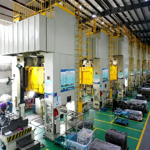
Milling holds tolerance because position comes from the machine axis, not from a consumable. A 3-axis or 5-axis cell positions to a few microns, so cavity datum features cut in the same setup stay in one coordinate system. EDM must transfer that accuracy through the electrode, the spark gap, and the burn depth. On open geometry, that transfer buys nothing.
Surface quality follows from stepover control. A 6 mm ball-nose tool at a 0.1 mm stepover leaves a theoretical cusp near 0.2 µm. Real finishing lands in the Ra 0.2-0.8 µm band. Tighter stepovers push Ra lower but multiply pass time, so most shops quote the band and let the program balance it. Cutter runout and machine stiffness decide whether the cusp math holds.
Hard milling also protects geometry that EDM erodes. Draft angles, blends, and shut-off lands are cut, not re-melted, so the surface stays true to the CAD model. Milled steel accepts polishing directly and holds detail through texture and plating. For cutter path basics on hardened work, see our guide on climb vs conventional milling.
When EDM Wins: Deep Ribs, Sharp Corners and Tight Cavities
Sinker EDM wins where a cutter physically cannot go. That means internal corners below a 0.1 mm radius, ribs beyond tool reach, and detail a ball nose would rub away. EDM copies the electrode, so the corner radius equals the electrode edge radius, dressed to 0.03-0.1 mm typical. A machined corner can never beat that because the cutter itself defines the minimum radius.
Deep ribs are the classic EDM case. A rib 20 mm deep and 2 mm wide sits far beyond comfortable milling reach, where long tools deflect and taper. Milling holds quality up to a depth-to-diameter ratio near 4-5 to 1. Beyond that, deflection and chatter cost hours. Sinker EDM reaches depth-to-width ratios of 10-20 to 1 with good flushing, because the electrode guides itself into the pocket.
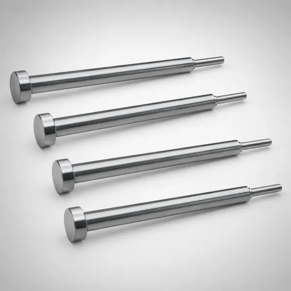
Sharp internal corners, lettering, and floor texture land here too. Connector molds carry letter stroke widths of 0.2 mm and small pocket details near 0.1 mm, all cut from copper electrodes at low current. Blind pockets have no exit for a wire, so sinker EDM is the only electrical route to their floors and walls.
Electrode material sets the burn quality. Graphite handles high current and large areas, so it roughs fast and costs $10-60 per block. Copper holds fine ribs and sharp edges at low current, where graphite edges chip, and it wears more predictably on finish burns. Most toolrooms stock both and pair a graphite rough with a copper finish on critical detail.
Flushing carries eroded debris out of the spark gap. Side flushing through 0.5-2.0 mm holes and electrode ports keeps the burn stable on deep ribs. Without it, debris re-ionizes the gap and the burn stalls at a fraction of the roughing rate. A finish burn then runs at low current on the same electrode set, trading removal speed for a thinner white layer.
Hardness does not slow EDM. The process erodes by spark, not by cutting edge, so a cavity at HRC 62 burns at the same rate as one at HRC 50. That is why hardened inserts with tight internal geometry route to the EDM cell after heat treat. To see where sinker and wire EDM split the work, read sinker EDM vs wire EDM.
Surface Integrity: White Layer vs Compressive Stress
The two routes change the steel surface differently, and that difference survives into service. Milling shears the surface and leaves compressive residual stress, typically -200 to -600 MPa in the outer 0.01-0.05 mm. Compressive stress resists crack initiation and helps a polished cavity hold its finish under molding pressure and thermal cycling.
EDM melts and re-solidifies a thin skin on every spark. That white layer, or recast layer, runs 0.002-0.015 mm typical depending on pulse settings. Beneath it sits a heat-affected zone where the base steel can re-harden or soften by a few HRC over a thin band. Rough settings leave microcracks in the white layer. Finish settings leave them rarely, but the risk never reaches zero.
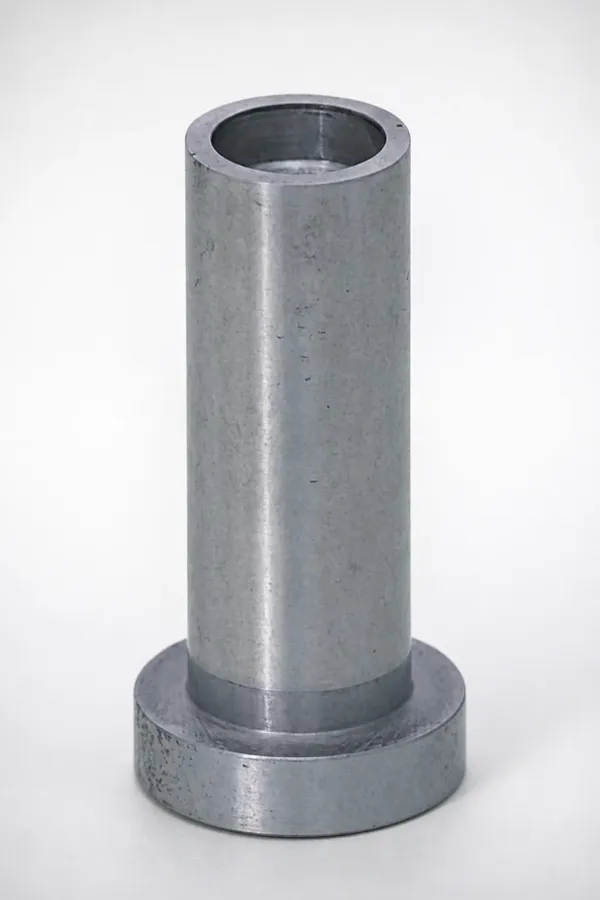
Removal restores the surface. Polishing away 0.01-0.03 mm, or running a low-current finish burn, takes off the white layer and its cracks. On shut-off edges, venting lands, sealing surfaces, and appearance areas, that removal step is not optional.
The integrity rule reads simply. If the finished surface sees wear, sealing, plating, texture, or cyclic load, mill it wherever the geometry allows. If EDM is the only route to the shape, budget the white layer removal into the finish pass and say so on the process plan.
Cost and Time: Comparing the Two Routes
Cost starts with material removal rate. Hard milling removes hardened steel at roughly 10-40 cm³/h with modern tooling, while sinker EDM burns at 5-15 cm³/h on a roughing electrode. Finish passes collapse that gap on paper but not on the clock. Fine burns drop below 1 cm³/h, while ball-nose finishing still removes useful stock.
Electrode cost is the second line. Graphite machines fast and costs little per block. The electrode drawing, 1-4 hours of graphite cutting, and the rough and finish electrode plan still add real hours before the first spark. Copper electrodes cost more and hold fine detail, and both materials wear 0.1-1% per burn typical.
| Route | Typical Removal, Rough | Typical Hourly Cost | Setup Add-Ons |
|---|---|---|---|
| Hard milling, open geometry | 10-40 cm³/h | $70-130 per hour | CAM program and fixture only |
| Sinker EDM, rough burn | 5-15 cm³/h | $90-170 per hour | Graphite or copper electrode, 1-4 h to cut |
| Ball-nose finishing pass | 0.5-3 cm³/h | Inside milling hour | Stepover control and on-machine check |
| Sinker finish burn | 0.1-1 cm³/h | Inside EDM hour | Second electrode, wear 0.1-1% per burn |
← swipe to scroll →
Table: typical U.S. machine-hour economics for hardened mold finishing. Rates vary by region and machine class.
Time shows up in machine hours and lead time. An open pocket that mills in 3-6 hours can take 8-24 hours through the EDM route once electrode prep is included. The reverse is true for deep ribs, where milling fights deflection for 2-3 times the EDM hours. Compare the routes per feature, not per process, and the quote stops leaking hours.
Run the arithmetic on a 250 x 150 mm cavity face. A milled finish at 0.5-3 cm³/h with a 4 hour program lands near $400-900 in machine time. The same face burned at 0.1-1 cm³/h on finish settings, plus an electrode cut of 1-4 hours, can run $900-2,500 before polishing starts. Open geometry pays for the mill on the first cavity.
Setup and quoting hours follow the same pattern. A milled feature needs one CAM program and one fixture, typically 1-3 hours of preparation. A burned feature needs the electrode drawing and 1-4 hours of graphite or copper machining. A burn plan for rough and finish electrodes is written before the first spark fires. That preparation shows up as a fixed charge, so two cavities with identical area can differ by $300-800 in setup alone.
The Hybrid Workflow: Mill First, EDM the Corners
The strongest route is often both. Mill every surface the cutter can reach, then burn only the corners, ribs, and details that milling cannot hold. Typical shops mill 70-90% of a cavity's finished area and EDM the rest. That split keeps the fast process on open geometry and the precise process on the hard-to-reach features.
Blending matters at the handoff. When EDM follows milling, the electrode overlaps the milled surface by 0.1-0.3 mm. The burn then removes cutter marks instead of leaving a witness line. Plan the boundary at a draft change or a blend radius rather than mid-wall. The spark gap, typically 0.01-0.05 mm at finish settings, is modeled into the electrode before graphite is cut.
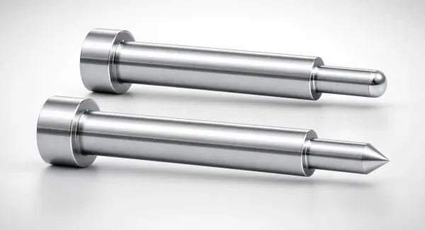
Process order for a hybrid cavity is fixed. Rough mill, heat treat to 48-62 HRC, hard mill the open faces, then burn corners and ribs with a rough and a finish electrode. Polish last. Each step holds its own tolerance band, and the mold book records which process made each surface. Rework stays local to one step instead of restarting the whole cavity.
Hybrid routing depends on upstream accuracy. The milled faces become the datum that electrodes burn against, so any error there repeats in the EDM detail. See precision CNC machining for mold components for what the rough-and-hard-mill stage should deliver.
Machining by Feature: A Decision Table
The table below routes the common cavity features. Use it at quoting time, then confirm the corner radius and finish class on the drawing before the process plan locks.
| Cavity Feature | Hard Milling | Sinker EDM | Typical Default |
|---|---|---|---|
| Open floor or wall wider than 25 mm | Fast, Ra 0.2-0.8 µm | Slow, needs electrode | Mill |
| Internal corner radius 0.05-0.1 mm | No, cutter radius limits 0.1-0.3 mm | Yes, electrode edge 0.03-0.1 mm | EDM |
| Internal corner radius above 0.3 mm | Yes, match ball radius | Possible, slow | Mill |
| Rib with depth-to-width ratio above 5 to 1 | No, deflection past 4-5 to 1 | Yes, flushing required | EDM |
| Blind pocket with open floor | Yes up to about 4 to 1 depth | Yes | Mill first |
| Lettering or texture on a pocket floor | No practical route | Yes, copied from electrode | EDM |
| Shut-off, sealing or wear surface | Yes, no recast layer | Only with white layer removal | Mill |
| Detail narrower than 0.15 mm | No | Yes, copper at low current | EDM |
| Large cavity with two sharp corners | Yes for the bulk | Yes for the corners | Hybrid |
← swipe to scroll →
Table: typical routing rules used in mold shops. Verify each row against your feature sizes, finish class, and supplier equipment.
Two rules make the table safe to use. First, when the drawing is silent on corner radius, the shop picks the route, and that pick may not match the molded part's requirement. Second, when a surface mixes an open area and a tight corner, split it into separate rows. Do not force one process on the whole cavity.
The hybrid row carries most real molds. A connector cavity mills its open wall and floor, then EDM burns the corner detail that the connector terminals actually seal against. Route the cavity as a list of features and the process plan writes itself.
Polishing and Finish: What Each Route Leaves Behind
What each route leaves behind decides the polishing bill. A finish-milled surface at Ra 0.2-0.8 µm polishes in roughly half the hours of an EDM surface at the same Ra. Its compressive skin stays uniform to the surface because the base steel is untouched by heat.
An EDM surface carries the white layer and a re-hardened zone beneath it. That skin polishes differently from the base steel, so the polisher must break through it before the finish reads evenly. Removing 0.01-0.03 mm of stock, depending on burn settings, clears the layer before the final polish sequence starts.

Finish class sets the removal budget. A rough burn leaves Ra 3-10 µm and needs 0.02-0.05 mm of removal to reach an SPI A or B gloss. A finish burn at Ra 0.2-0.8 µm needs only 0.005-0.015 mm, which is why the finish electrode pays for itself on appearance cavities. High-gloss A-band surfaces on automotive lenses and medical parts almost always route to milling plus polish.
Where a surface will be coated, the base finish matters as much as the coating. PVD and DLC layers sit 1-5 µm thick and replicate whatever is underneath. A cracked EDM skin or a rough polish reads straight through the coating. Milled compressive surfaces give plating and texture etching a uniform base. That is why optical and wear surfaces route away from the burn when geometry allows.
Texture reads the same way. EDM spark texture is sometimes intentional for grip, but molded optics, glazing, and plating surfaces reject any residual spark pattern. Milled and polished surfaces accept photo-etching and coating without the recast variable. For the full pass sequence and grit ladder, see our mold polishing guide from Ra 3.2 to SPI A1.
RFQ Call-Outs That Decide the Route
The RFQ decides the route before the shop does. State the minimum internal corner radius on the drawing. A 0.05 mm radius sends a corner to EDM. A 0.3 mm radius keeps it on the mill. State the surface finish by SPI class or Ra value per surface, not per cavity, because appearance areas and shut-offs rarely share a class.
Write the integrity call-outs explicitly. Say whether white layer or re-melted material is acceptable on shut-offs, vent lands, sealing surfaces, and appearance areas. Add texture zones with depth and pattern references, since texture is often EDM-only and needs its own electrode and burn plan.
Add the feature details that force the quote: rib depth-to-width ratio, pocket depth, lettering stroke width, and draft angle. Ask the supplier to list the planned process per cavity surface, with expected Ra and white layer treatment on each line. A quote that names the route has already costed it. A quote that stays silent has not.
Close the loop on inspection. Confirm how corner radius will be measured, by optical comparator, CMM, or mold replica, and state the acceptable deviation, typically ±0.01-0.02 mm on that check. Confirm whether the first article must verify white layer removal by metallurgical cut or etch check on a test coupon. Those two lines separate a mold that ships from a mold that negotiates.
Lead time enters the RFQ the same way. A milled route can start as soon as the CAM program passes its dry run, often the same day. An EDM route waits on the electrode, and a re-burn waits on a new one. Ask for the process plan, the electrode count, and the expected white layer treatment in the quote. The route decision then belongs to engineering, not to the busiest machine on the floor.
FAQ: Hard Milling vs EDM for Molds
Q1. When should I specify hard milling over EDM for cavity details?
Specify hard milling for open geometry where the cutter reaches and the internal corner radius stays above 0.1-0.3 mm. Milling delivers Ra 0.2-0.8 µm finishes with no recast layer, compressive residual stress near -200 to -600 MPa, and hours of lead time saved. It is the default for floors, walls, and shut-off lands in 48-62 HRC steel.
Q2. What corner radius can EDM produce that milling cannot?
A dressed electrode burns internal corners of 0.03-0.1 mm, while a ball-nose cutter leaves a radius equal to its own, 0.1-0.3 mm typical. If the drawing calls a corner under 0.1 mm, route it to EDM. Add the spark gap of 0.01-0.05 mm at finish settings when you review the electrode model.
Q3. Is the EDM white layer always a problem?
No, but it must be managed. The white layer runs 0.002-0.015 mm typical, and polishing away 0.01-0.03 mm or running a low-current finish burn removes it. It is a real risk on shut-offs, sealing surfaces, plating areas, and fatigue-loaded detail. It is harmless on most interior floors that take texture or light polish.
Q4. Which process is faster for a given cavity?
It depends on the feature mix. An open pocket mills in 3-6 hours versus 8-24 hours through EDM with electrode prep. A deep rib with a depth-to-width ratio above 5 to 1 burns faster than milling can fight deflection. Compare per feature. Most production cavities save the most time as a hybrid.
Q5. Can one cavity use both milling and EDM?
Yes, that is the standard hybrid. Mill 70-90% of the finished area, then EDM the corners and ribs with a rough and a finish electrode. Overlap the burn into the milled surface by 0.1-0.3 mm so no witness line remains. Record which process made each surface in the mold book.
The Bottom Line
Route selection is a feature-level decision, not a machine preference. Milling wins open geometry at Ra 0.2-0.8 µm with no recast layer and shorter lead time. EDM wins corners below 0.1 mm, ribs beyond a 5 to 1 depth ratio, and detail past cutter reach. The price is a 0.002-0.015 mm white layer and electrode hours.
Most precision cavities end up hybrid: mill the open area, burn the corners, and budget the polish that clears each surface. Put the corner radius, finish class, and integrity limits in the RFQ, and the shop picks the route the part actually needs. That discipline turns a 0.05 mm corner from a buy-off failure into a line item.
DieStrike machines and burns cavity steel to HRC 62 under IATF 16949 with 120+ machines. Long-running connector programs for OEMs such as TE Connectivity, Amphenol and Luxshare run through the same floor. Production molds are quoted in 2-5 weeks, and standard mold components ship in 3-7 days.
KEEP READING
Related Reading
Sinker EDM vs Wire EDM: Which Cuts Your Mold
Wire EDM holds ±0.002-0.005 mm on skimmed profiles, while sinker EDM burns blind cavities at Ra 0.2-0.8 µm.
Read articlePRECISION GUIDEHow to Hold ±0.002mm: Precision Mold Tolerances
What ±0.002 mm means on a drawing, how shops measure it, and where it holds in hardened steel after heat treat.
Read articleMOLD FINISHINGMold Polishing Guide: From Ra 3.2 to SPI A1
Polish from Ra 3.2 to SPI A1: stone grits, diamond compounds, and pass sequence for EDM and milled surfaces.
Read articleMACHINING GUIDEClimb vs Conventional Milling: Which Cut to Use
Climb vs conventional milling on hardened steel: chip load, up to 50% longer cutter life, and when each cut wins.
Read articleNEXT STEP
Ready to Start Your Mold?
Send us your element dimensions or part numbers — our team responds within 24 hours with pricing and lead time.

Written by
Ray ChanMold Buyer's Guide Author · Precision Mold Manufacturing Specialist. Ray helps global importers, distributors and OEMs source factory-direct molds and mold parts.