
Sinker EDM vs Wire EDM: Which Cuts Your Mold | DieStrike
Table of Contents
A 6.0 mm deep blind pocket went to a wire EDM cell and stalled the mold build for nine days. Wire EDM cannot cut blind features. The shop re-quoted the insert for sinker EDM and burned a graphite electrode overnight.
The insert still shipped with a 0.02 mm recast layer on the wall. The second burn and the rework added about $1,800 to a $2,400 insert. The T1 trial slipped two weeks. Process selection lost that money before any electrode was cut.
The Snapshot
- Wire EDM cuts through profiles and holds ±0.002 to 0.005 mm typical on skimmed features.
- Sinker EDM forms blind cavities at ±0.005 to 0.01 mm typical with a dressed electrode.
- Finished surfaces land at Ra 0.1 to 0.4 µm for wire skim passes and Ra 0.2 to 0.8 µm for sinker finish burns, typical.
- White layer runs 0.005 to 0.03 mm typical and needs skim passes or polishing before plating and texture.
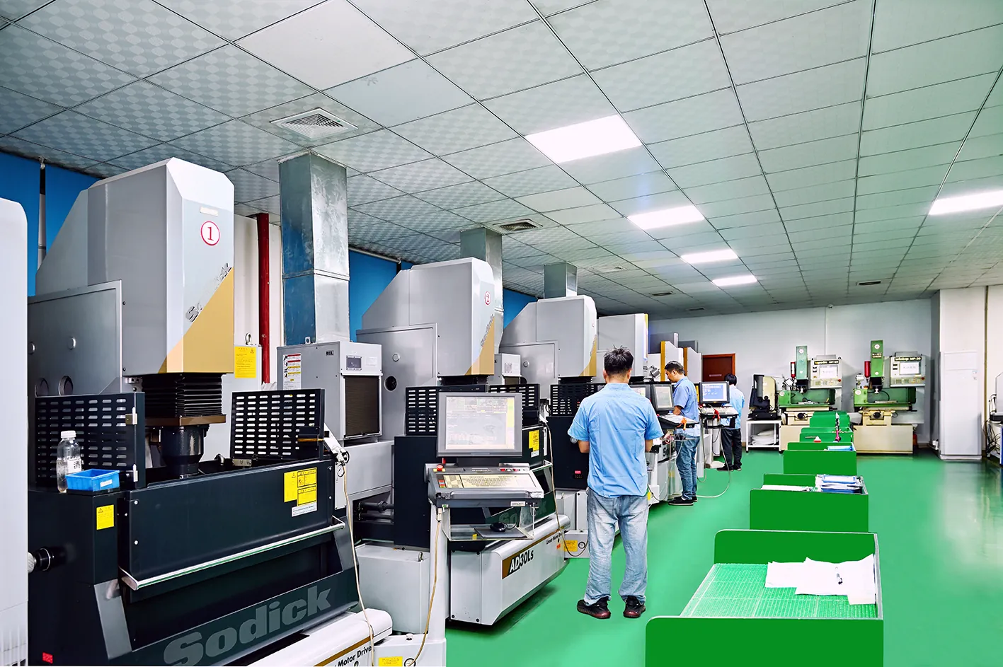
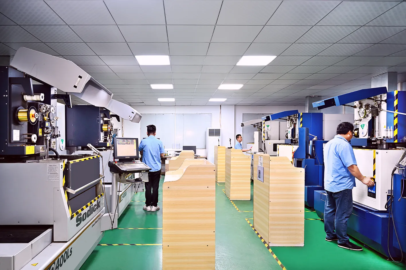
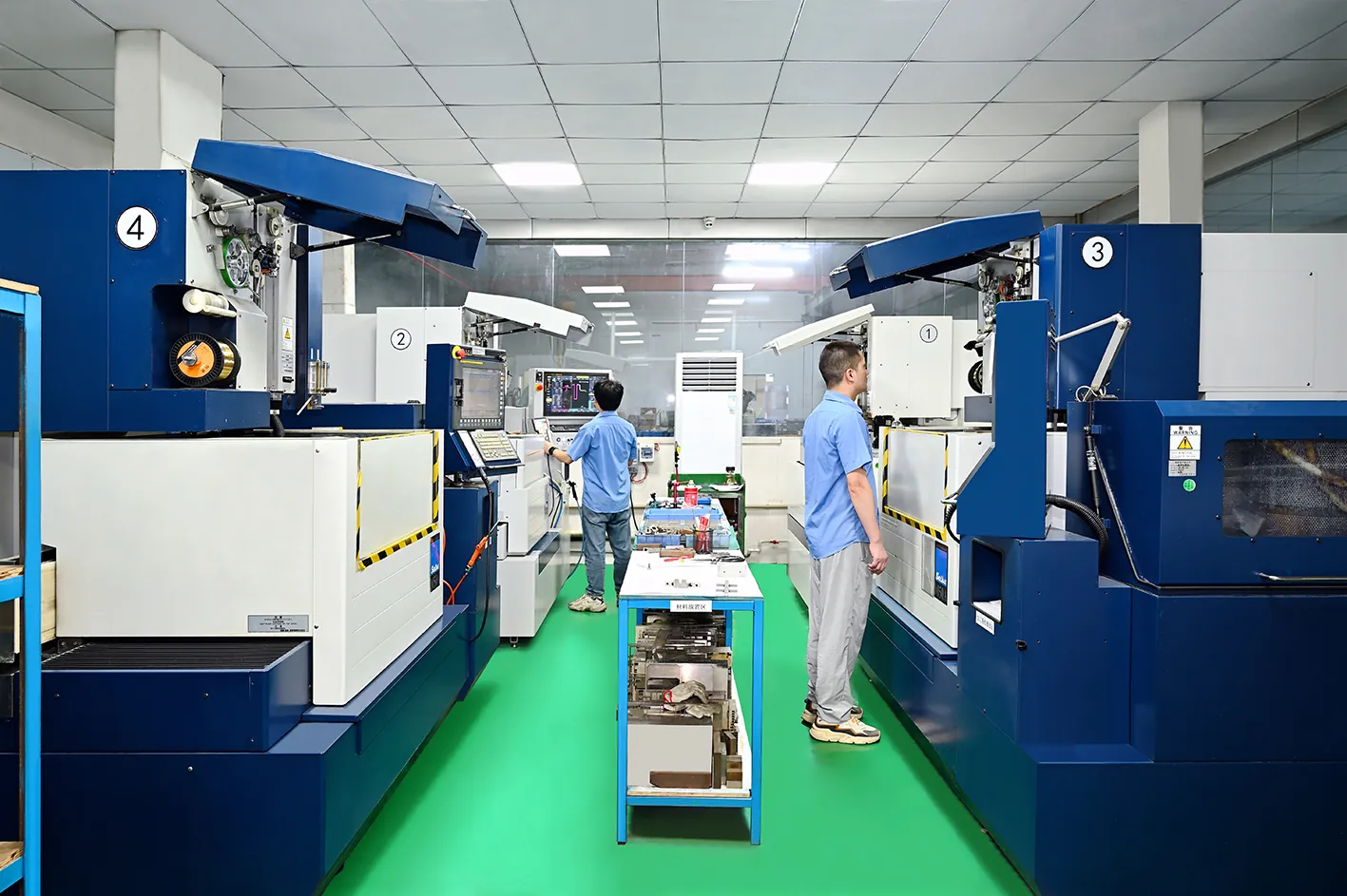
- DieStrike runs Sodick sinker EDM cells and wire EDM cells in an IATF 16949 shop with 120+ machines. Injection molds ship in 2 to 4 weeks.
Wire EDM cuts through profiles at ±0.002 to 0.005 mm typical. Sinker EDM forms blind cavities at ±0.005 to 0.01 mm typical. The two numbers look close until you multiply by electrode cost, white layer removal, and rework risk. Buyers who match the process to the feature keep the difference.
This guide covers what each process cuts, the tolerance it holds, the corners it can form, and what the machine hour actually buys. It ends with a decision matrix for the quoting engineer. All production bands below are typical industry figures.
How Each Process Cuts
Both processes erode steel with controlled electrical discharges in dielectric fluid. The difference is the tool. Sinker EDM uses a shaped electrode. Wire EDM uses a moving wire, and that one difference decides which features each can form.
Sinker EDM: A Shaped Electrode Transfers Its Form
A graphite or copper electrode is machined to the mirror image of the target cavity. The ram lowers it into the steel under dielectric, and each pulse erodes a microscopic crater. The burn transfers the electrode form into the part, floor, walls, and corners together. Spark gap runs 0.01 to 0.05 mm typical at finish settings, so the final cavity is the electrode plus that gap.
Electrode material splits the work. Graphite burns fast at high current, so it handles roughing and large faces. Copper holds fine ribs and sharp detail at low current, where graphite edges chip. Most toolrooms keep both in stock.
Electrode wear is real. Finish burns run 0.1% to 1.0% volume wear per electrode typical. Critical blind features get two electrodes, one for roughing and one for finish, so the last burn matches the drawing.
Wire EDM: A Tensioned Wire Cuts the Profile
Wire EDM threads a wire, typically 0.15 to 0.30 mm diameter, through a starter hole. Tensioned between guides, the wire erodes a slot as the CNC paths the profile. Slot width is wire plus spark gap, roughly 0.3 mm for a 0.25 mm wire. The wire never touches the workpiece.
The wire needs a path through the blank. Through slots, holes, external contours, and tapered walls cut cleanly. Blind floors and pocket interiors are out of reach. Starter holes are drilled first, often 0.3 to 1.0 mm diameter, and that step is part of the cycle.
Hardened steel cuts as easily as annealed stock on wire EDM. That is why DieStrike profiles inserts, punches, and strippers after heat treatment at HRC 62, where conventional milling loses its edge.
What Sinker EDM Is Best At
Sinker EDM owns the geometry a cutter cannot reach and a wire cannot see. Blind cavities, deep pockets, ribs, lettering, and internal corners all route to the ram. If the feature has no through opening, sinker EDM is the process to cost.
Blind Cavities and Deep Pockets
A blind cavity has no exit for a wire. The sinker electrode burns the floor, the walls, and the corner radii in one setup. DieStrike burns cavities after hardening, so the block is machined, heat treated to HRC 62, and only then finished by EDM.
Depth changes the electrode plan. A 6 mm deep pocket burns predictably with one roughing electrode and one finishing electrode. A 40 mm deep ribbed pocket needs stepped electrodes, flushing holes, and longer burn time. Electrode flushing holes run 0.5 to 2.0 mm diameter typical and pull debris out of the gap.
The burn leaves the cavity floor and walls from the same electrode, so geometry stays coherent. Draft, radii, and texture transfer together. Rework means a new electrode, which is why the electrode drawing is checked before the graphite is cut.
Ribs, Lettering, and Small Internal Detail
Engraved lettering, part numbers, and mold texture patterns are sinker work. A wire cannot reach a pocket floor. Copper electrodes at low current hold rib widths near 0.1 mm typical, and letter stroke widths of 0.2 mm are routine in connector molds.
Fine detail needs low energy. Current settings drop below 1 A for the finish pass, and each crater shrinks with the energy. A fine sinker burn polishes to the SPI A band faster than a rough burn does.
What Wire EDM Is Best At
Wire EDM cuts geometry that passes through the blank. Insert outlines, through holes, slots, punches, and tapered walls are its native work. It runs unattended, holds tight tolerance, and leaves a surface many molds use as cut.
Insert Profiles, Punches, and Through Features
An insert blank is profiled from hardened steel, and the wire path becomes the parting edge. The profile needs no electrode and no burn compensation beyond the wire offset. Wire diameter plus gap is entered once in the CAM, and the slot repeats to the same band across the blank.
Through holes and slots follow the same logic. Slot widths down to 0.2 mm are feasible with a 0.15 mm wire at low energy. Punches for stamping dies cut from the same hardened blank, so the punch profile and the die plate profile match from one program.
Wire EDM holds ±0.002 to 0.005 mm typical on these profiles with skim passes. The band includes the die plate and the punch when both cut in the same setup. Clearance between punch and die is then a CAM offset, not an assembly gamble.
Tapered Walls and Stacked Blanks
Wire guides tilt to cut draft and relief angles. Precision machines hold 1 to 15 degrees per side typical, with accuracy falling as angle and stock thickness rise. Stripper relief and gate details use that tilt.
Stacking multiplies the output. Several thin plates clamp together and cut as one stack, sharing one program and one tolerance band. Four stripper plates at 8 mm each cut in roughly the time of one 32 mm plate.
Tolerance Comparison
Tolerance claims follow geometry. Wire numbers below apply to through features cut with skim passes. Sinker numbers apply to blind forms finished with low-current electrodes. Compare like for like, and the two bands stop looking alike.
Two Typical Bands
A skimmed wire cut on hardened tool steel typically holds ±0.002 to 0.005 mm on position and profile. Machine repeatability sits inside the same band on a temperature-stable floor. DieStrike holds overall mold precision at ±0.005 mm, with critical features at ±0.002 mm, and checks each burn on the CMM.
Sinker EDM typically lands at ±0.005 to 0.01 mm on blind forms. Electrode wear, flushing pressure, and side gap all move the burn. Critical blind features get compensated electrodes, sized from the measured wear of the first electrode.
Surface finish follows the same split. Wire with multiple skim passes lands at Ra 0.1 to 0.4 µm typical. Sinker finish with fine copper electrodes lands at Ra 0.2 to 0.8 µm typical, and both polish further.
| Attribute | Wire EDM Typical | Sinker EDM Typical |
|---|---|---|
| Position and profile tolerance | ±0.002 to 0.005 mm | ±0.005 to 0.01 mm |
| Surface finish after finish passes | Ra 0.1 to 0.4 µm | Ra 0.2 to 0.8 µm |
| Blind cavity or pocket | No, wire needs a through path | Yes, native geometry |
| Through slot or external profile | Yes, native geometry | Possible with a form electrode |
| Cut after hardening, HRC 58 to 62 | Yes, no distortion | Yes, no distortion |
| Typical verification | CMM profile scan | CMM plus electrode check |
← swipe to scroll →
Typical production bands. Final numbers depend on generator settings, skim count, and flush quality.
Where the Number Gets Verified
DieStrike verifies burned features against the drawing, never against the CAM path. A Zeiss CMM scans position, profile, and draft after the last skim or polish pass. Results go into the mold book with the electrode record, so a later rework starts from measured data.

Verification decides the tolerance argument. A wire profile at ±0.002 mm and a blind pocket at ±0.005 mm both need a machine that can measure them. DieStrike documents every EDM feature before the insert leaves the toolroom.
Corner and Radius Limits
Every EDM process rounds the corners it forms. The radius is set by the wire diameter or the electrode edge, and it lands on the part drawing as an internal corner callout. Skip the check, and the first cavity comes out with the wrong corner.
Wire corners follow the wire. The cut slot carries a radius on every path corner, internal and external. Minimum internal radius is about half the slot width, wire radius plus spark gap. Expect roughly 0.1 to 0.2 mm typical with a 0.15 to 0.25 mm wire.
Sinker corners follow the electrode. Internal radii on blind features reach 0.02 to 0.1 mm typical with dressed graphite or copper electrodes. The limit is electrode edge wear at high current, which rounds the corner during the burn. A fresh finish electrode restores the corner.
| Feature or Corner | Sinker EDM Typical | Wire EDM Typical |
|---|---|---|
| Blind pocket internal corner | 0.02 to 0.1 mm, dressed electrode | Not possible, wire needs a through path |
| Through slot internal corner | 0.05 to 0.15 mm with a form electrode | 0.1 to 0.2 mm, 0.15 to 0.25 mm wire |
| Part external profile corner | Limited by electrode edge wear | 0.1 to 0.2 mm typical, CAM corner control optional |
| Deep cavity floor to wall corner | 0.05 to 0.3 mm, depends on depth | Not applicable |
| Lettering and rib edges | 0.02 to 0.1 mm typical, low current | Not applicable, through features only |
← swipe to scroll →
Typical industry figures. Corner control programs and multiple electrodes can push the numbers lower on specific jobs.
When the drawing demands a sharper corner than the process holds, the answer is a secondary operation, not a wish. Sinker parts may need a stoning pass on the corner. Wire parts may need a finer wire or a corner-control program.
White Layer and Skim Passes
What the Recast Layer Does
EDM melts a thin skin of steel and re-solidifies it as a white layer. The layer is harder, micro-cracked, and weaker than the parent metal. Typical thickness runs 0.005 to 0.03 mm, thicker after heavy roughing passes.
White layer fails in service. On a shutoff edge or ejector land it flakes and opens flash paths. Under thermal cycling the micro-cracks grow, and plating or texture coating peels from the recast skin. Molds that skip removal pay for it at the trial stage.
Skim Passes Remove It
Skim passes are low-energy cuts that shave the recast layer off in thin slices. Wire machines run one to three skims after the first cut. Sinker cells repeat the burn with a finish electrode at low current.
Each skim improves finish and removes more white layer. Typical production practice plans the skim count into the quote, because a cavity sold with three finishing passes cannot ship with one. Ra drops with every pass toward the Ra 0.1 to 0.4 µm band.
What remains after the last skim is a thin, crack-free skin that polishes or textures cleanly. DieStrike records the skim count and the final Ra in the mold book, so the next cavity repeats the same surface.
Cutting Speed and Machining Time
Time is quoted in machine hours, and each process spends them differently. Wire time follows the cut area and the skim count. Sinker time follows the electrode face and the depth of the burn.
Wire: Roughing Rates and Skims
Wire roughing on hardened tool steel typically removes 20 to 60 mm²/min of cut area in the first pass. Thicker stock cuts slower in feed terms at the same area rate. A 40 mm thick insert blank sits at the slow end of that band.
Skims cost time on the same path. Each skim pass commonly runs at 30% to 60% of the roughing feed. A two-skim job can double the machine time of the first cut. Quote by the meter of wire path, not by the part.
Threading and setup add fixed minutes per feature. Automatic re-threading runs 15 to 60 seconds typical per hole, and thin-wall slug handling adds more. That is why many small holes cut faster in one setup than across scattered programs.
Sinker: Burn Time Scales With Electrode Area
Sinker time follows the electrode face. A 20 by 30 mm pocket face burns faster than a 60 by 60 mm face at the same depth. Typical graphite roughing on hardened steel removes 15 to 60 mm³/min at high current, and finish passes drop below 1 mm³/min.
Flushing rules the long jobs. Deep narrow pockets need flushing holes in the electrode, which add electrode cost but cut burn hours. A 40 mm deep ribbed pocket is a multi-hour burn, and the quote should say so before steel is cut.
Electrode wear adds a second burn on critical features. One roughing electrode and one finishing electrode roughly doubles the EDM time on that feature compared with a single burn. DieStrike plans the electrode set during DFM, so the quoted time matches the floor.
Cost Structure Compared
The machine hour rate is the smallest part of the cost story. Sinker EDM carries electrode design and machining. Wire EDM carries wire, filters, and skim passes. The structure decides which process is cheaper for your feature set.
Sinker: The Electrode Is the Hidden Line
Someone machines the electrode before the burn starts. A graphite block for a small cavity costs $10 to $60 typical. CNC milling of a ribbed or 3D electrode runs $80 to $500 typical per set, and most features use two or three electrodes.

Electrode strategy decides the margin. One roughing electrode and one finishing electrode is the baseline. Add flushing holes, and electrode cost rises while burn time falls. Complex blind cavities can spend more on electrodes than on EDM hours.
Wire: Hours, Wire, and Skims
Wire cost is real but small. A 0.25 mm brass wire consumes roughly $2 to $6 per machine hour, with filters and resin on top. The machine hour dominates a simple through profile, which is why wire wins on plain geometry.
Skim passes multiply the bill. Two skim passes can double to triple the machining time of a single-cut profile. Put the skim count on the drawing, so the tolerance matches the passes that hold it.
| Cost Driver | Sinker EDM Typical | Wire EDM Typical |
|---|---|---|
| Machine rate | $60 to $120 per hour | $40 to $90 per hour |
| Setup and programming | 1 to 4 hours plus electrode CAD | 1 to 3 hours plus thread points |
| Electrode and consumables | Graphite $10 to $60 per block, milling $80 to $500 per set | Brass wire $2 to $6 per hour, filters and resin extra |
| Finishing passes | Second electrode at low current | Skims add 30% to 100% of cutting time |
| Recast layer removal | Polish after the finish burn | Skims remove most of the layer |
← swipe to scroll →
Typical industry ranges for precision toolroom work. Rates vary by region, machine age, and workpiece size.
DieStrike quotes from the feature, not from the process name. The DFM review returns within 24 hours. A process selection with a cost breakdown follows within 48 hours, so the electrode line is visible before you sign.
Surface Finish and Polishing Path
The finish that leaves the machine is not the finish that enters production. EDM texture, recast depth, and polishability decide whether the cavity runs as cut or visits the polishing bench. Plan that step in the quote.
Reading Ra and SPI Grades
SPI grades run from A1, a mirror finish, to D3, a rough sandblast. Wire skim finish at Ra 0.1 to 0.4 µm is often used as cut on shutoff edges and stripper bores. Sinker finish at Ra 0.2 to 0.8 µm usually needs a polish step before it reaches the SPI B or A band.
Polishing from Ra 0.8 µm down to SPI B-2 takes 400 to 600 grit stones, typical shop practice. SPI A grades add diamond compounds from 6 µm down to 1 µm. The path is shorter when the EDM finish pass did its job.
Two Polish Paths for Two Surfaces
Blind cavities polish from the sinker finish burn. The floor, walls, and corners carry the same texture, so the polisher works one surface type. Through profiles cut by wire are stoned on edges and used as cut on the faces.
Remaining recast must go before plating or texture etching. Plating bonds to sound steel, not to a cracked skin. DieStrike polishes cavities from the EDM finish at HRC 62. The final Ra is recorded in the mold book, so the texture step starts from a verified surface.
Decision Matrix
Run the feature through the gates in order. Geometry first, tolerance second, cost third. The table below is a first pass for the quoting engineer, and the drawing review settles the final call.
| Situation | Process | Why It Wins |
|---|---|---|
| Blind cavity, pocket, or undercut form | Sinker EDM | Wire needs a through path, and the electrode carries the 3D form |
| Through hole, slot, or insert profile | Wire EDM | No electrode needed, ±0.002 to 0.005 mm typical with skims |
| Lettering, ribs, or detail on a pocket floor | Sinker EDM | Copper electrode at low current, detail down to 0.1 mm typical |
| External contour on a HRC 58 to 62 blank | Wire EDM | Cuts after hardening with no distortion |
| Tapered relief or draft walls | Wire EDM | Guide tilt of 1 to 15 degrees per side typical |
| Insert with a blind form plus through holes | Both, in sequence | One blank, two cells, one drawing |
← swipe to scroll →
Route by geometry first. Tolerance and volume then decide skim counts, electrode sets, and delivery.
Buyers who source mold making as a service can hand this matrix to the quoting engineer with the part drawing. DieStrike runs sinker and wire cells under one roof, so mixed features get one quote and one quality plan.
Volume changes the answer, not the process. A single prototype insert favors wire when the geometry allows, because no electrode is cut. A long-run production insert favors the process that holds tolerance with the least maintenance, which is the matrix call above.
When You Need Both
One Insert, Two Cells
A mold insert rarely belongs to one process. The pocket is sunk for the part form, and the outline, the through holes, and the taper are wire cut. Custom mold inserts built this way carry the form tolerance from the burn and the edge tolerance from the wire.
Sequence decides quality. Sinking first and wire cutting the outline second removes burn-affected steel from the parting edge. Cutting the outline first leaves a reference edge for electrode alignment. DieStrike fixes the order on the process sheet before steel is cut.
What a Combined Floor Delivers
A shop with both processes quotes geometry instead of machines. Blind features, through features, and replacement inserts stay on one RFQ, one DFM, and one delivery schedule. DieStrike, an IATF 16949 certified shop with 120+ machines, runs Sodick sinker EDM cells and wire EDM cells in the same toolroom.
Standard inserts, ejector pins, punches, and mold bases ship in 3 to 7 days. Complete injection molds ship in 2 to 4 weeks. Cavity steel runs HRC 62, and every feature is verified before assembly.
Tolerance stacks are the reason to keep both processes in one shop. When the sinker burn and the wire profile meet on one insert, the reference surfaces come from the same setup plan. That keeps overall mold precision at ±0.005 mm, with critical geometry at ±0.002 mm.
Frequently Asked Questions
Q1. Can wire EDM cut a blind cavity? No. The wire needs a starter hole and a path through the blank, so floors and pocket interiors are out of reach. Blind cavities route to sinker EDM, which typically holds ±0.005 to 0.01 mm with a dressed electrode. Pockets deeper than 6 mm also need flushing holes in the electrode.
Q2. Which process holds tighter tolerance? On through features, wire EDM with skim passes typically holds ±0.002 to 0.005 mm. On blind forms, sinker EDM lands at ±0.005 to 0.01 mm typical. DieStrike holds overall mold precision at ±0.005 mm, with critical features at ±0.002 mm, verified on the CMM.
Q3. Why does sinker EDM need electrodes, and what do they cost? The electrode is the inverse of the cavity form, and the burn transfers that form into the steel. Graphite blocks run $10 to $60 typical, and milling a ribbed or 3D electrode runs $80 to $500 per set typical. Most features use two to three electrodes, one for roughing and one for finish.
Q4. Do EDM surfaces need polishing before plating or texture? Yes, and the reason is the white layer. Recast skin of 0.005 to 0.03 mm typical micro-cracks and rejects plating adhesion. Skim passes remove most of it, and a polish pass clears the rest before texture etching or coating.
The Bottom Line
Geometry decides the process. Wire EDM holds ±0.002 to 0.005 mm on through features. Sinker EDM forms blind cavities at ±0.005 to 0.01 mm with electrodes that carry real cost. Matching the process to the feature keeps white layer, rework, and lead time off the mold budget.
Send the part drawing to DieStrike for a process review. DFM feedback returns within 24 hours, and a process selection with a cost breakdown within 48 hours. Standard parts ship in 3 to 7 days, and complete injection molds in 2 to 4 weeks.
KEEP READING
Related Reading
Wire EDM for Mold Making: Accuracy, Surface, and Cost
Wire EDM accuracy, surface, and cost on mold components: skim passes, ±0.002 to 0.005 mm tolerance, and electrode-free profiling.
Read articleArticleMold Polishing Guide: From Ra 3.2 to SPI A1
Mold polishing from Ra 3.2 to SPI A1: stone grades, diamond compounds, and the pass sequence for EDM surfaces.
Read articleArticleHow to Hold ±0.002mm: Precision Mold Tolerances
What ±0.002 mm means on a mold drawing, how it is measured, and where shops hold it in hardened steel.
Read articleArticleHow to Repair a Damaged Mold: 7-Step Workflow
7-step workflow to repair a damaged mold: weld, re-machine, re-burn, and verify EDM features back to print.
Read articleNEXT STEP
Ready to Start Your Mold?
Send us your element dimensions or part numbers — our team responds within 24 hours with pricing and lead time.

Written by
Ray ChanMold Buyer's Guide Author · Precision Mold Manufacturing Specialist. Ray helps global importers, distributors and OEMs source factory-direct molds and mold parts.