
How to Specify Mold Inserts: Fit, Steel and Design
Table of Contents
A mold insert that does not seat is not a quality issue. It is a production stop. A loose cavity insert shifts under injection pressure, parts flash, and the press comes down. Re-fitting one pocket typically runs 4-8 hours of machine time, and that is before the trial hours. Wrong insert specifications are one of the most common causes of avoidable mold downtime.
This guide covers the three decisions that define an insert: fit, steel, and design. You will see when an insert beats a solid cavity, how tight the pocket fit should be, and which steel serves which function. You will also see how locating, cooling, venting, and documentation turn a replaceable block into a controlled tool.
DieStrike writes this from shop-floor data. We are an IATF 16949 and ISO 9001 certified precision mold maker running 120+ machines in one factory. Standard mold features hold ±0.005 mm, precision features ±0.002 mm, and hardened cavity steel reaches HRC 62. Production molds ship in 2-5 weeks, and standard parts such as ejector pins ship in 3-7 days. Customers including TE Connectivity, Amphenol, Luxshare, and Dongshan Precision run programs on our tooling.
The Snapshot
- Pocket fit: 0.005-0.015 mm typical interference for small inserts; H7/k6 typical for cylindrical inserts.
- Insert change time: 1-2 hours typical when the fit, screws, and dowels are standardized.
- Steel by function: P20/718 for prototypes, H13 for core inserts, S136/420 for corrosion, BeCu for heat, carbide for wear.
- BeCu conducts roughly 3-10× the heat of tool steel, typical by alloy.
- A wrong fit or steel adds 4-8 hours of rework per insert, typical, before the mold returns to the press.
What Is a Mold Insert and Why Split the Cavity?
A mold insert is a removable block that forms part of the cavity or core surface. It sits in a pocket machined into a plate or a larger block. The part touches the insert face; the plate behind it carries the load and the alignment.
The solid cavity is the simpler alternative. One block holds the whole form, and there is no pocket, no fit, and no seam. For a single-material tool with a predictable life, solid construction is often the cheaper path.
Inserts exist because not every mold should be one block. A replaceable insert turns a wear point into a service item. It turns a hard-to-machine feature into a small, EDM-friendly block. And it lets the toolmaker swap steel, geometry, or material without re-cutting the entire cavity.
Five situations push a design toward inserts: replaceable wear zones, multi-material molding, hard-to-reach geometry, cost reduction, and planned design changes. Each one pays for the pocket in a different currency, and each carries its own fit and steel requirements.
When to Use Inserts vs a Solid Cavity
The decision is economic before it is technical. Ask what the feature will cost over the mold's life, not what the block costs today.
Wear zones justify inserts when they fail before the rest of the cavity. A gate that erodes at 500,000 shots typical forces a choice: re-cut the whole cavity, or unbolt a worn insert. Insert steel can also be upgraded in place, so the second insert often lasts longer than the first.
Multi-material molding nearly forces inserts. Two-shot tools need the first material to form a cavity for the second shot. That first-shot cavity is an insert by definition, and its steel must survive the second material's melt temperature.
Hard-to-machine geometry is another trigger. A deep ribbed core with internal shut-offs is easier to wire-EDM as a separate block than to mill inside a large plate. Inserts keep the machine envelope small and the tolerance chain short.
Cost reduction works the other way. A 60 mm wear insert costs a fraction of a 400 mm cavity block, so each replacement is cheaper per event. The pocket itself costs money up front, typically 1-3 hours of machining and fitting, and pays back at the first swap.
Design changes justify inserts when the part is still moving. Bridge tooling with planned revisions uses replaceable inserts, so the second revision does not scrap the base. The same pocket accepts the revised insert, which cuts revision cost roughly in half typical.
Insert Types: Cavity, Core, Gate, and Wear Inserts
Insert designs fall into four working families. Each family has a typical steel, a typical fit, and a job to do. The table below summarizes the defaults; the sections that follow explain the trade-offs.
| Insert Type | Function | Typical Steel | Typical Fit |
|---|---|---|---|
| Cavity insert | Forms the outside surface of the part | P20, 718H, S136 | 0.005-0.015 mm interference |
| Core insert | Forms internal geometry and shut-offs | H13, S136 | 0.005-0.015 mm interference |
| Gate insert | Localizes gate wear and erosion | H13, tungsten carbide | 0.01-0.02 mm clearance |
| Wear insert | Protects slide faces, locks, and guides | Carbide, D2 | Slip or press fit |
| BeCu insert | Removes heat from hot spots | Beryllium copper | 0.01-0.02 mm clearance |
← swipe to scroll →
Cavity inserts
A cavity insert forms the visible outside of the part. It carries the polish or texture, so its steel must hold the finish for the program life. P20 and 718H work for most programs; S136 is the standard when the resin attacks the surface or the part must stay clear.
The cavity insert is usually the largest insert in the mold. Its pocket fit is the tightest, because any movement shows as a witness line or flash on the part surface.

A 300 mm cavity insert in 718H starts as a machined block at 33-38 HRC typical, then gets finish-milled and polished to the specified finish. We machine cavity inserts on 3- and 5-axis machining centers and verify the form on a CMM before assembly.
Core inserts
A core insert forms internal geometry: holes, ribs, bosses, and shut-offs. It sees the highest melt pressure of any insert, because injection pressure pushes the plastic against the core surface.
Core inserts are the most likely to be hardened. H13 at 44-52 HRC typical survives high melt temperatures and high cycle counts, and S136 serves when corrosion or clarity matters. Sharp core features are wire-EDM'd after heat treatment rather than milled soft.
Gate inserts
Gate inserts localize the highest-wear point in the mold. Melt velocity peaks at the gate, so erosion concentrates there, and a hardened gate insert protects the cavity behind it.
Gate inserts run H13 or carbide, depending on the resin and the cycle count. Glass-filled nylon erodes soft steel fast; a carbide gate insert at 88-93 HRA typical can outlast several steel gates. The insert also makes gate tuning cheap, because adjusting gate size is a small re-cut, not a cavity operation.
Wear inserts
Wear inserts protect sliding and locking surfaces: slide faces, lock blocks, and guide surfaces. They are flat or simple blocks that take the abrasion so the main structure does not.
Carbide and D2-class steel are the usual choices. D2 at 58-62 HRC typical serves where toughness matters; carbide serves where hardness does. Because they are small and standard, wear inserts are often stocked and replaced in minutes.
Insert Steel Selection by Function
Steel choice decides whether an insert lasts a program or fails mid-run. Four drivers matter: hardness, toughness, corrosion resistance, and thermal conductivity. No grade wins all four, so the insert function picks the grade.
P20 and 718H for prototype and low-volume inserts
P20 at 28-32 HRC typical machines fast and polishes well. It suits prototype inserts and low-volume production where the program will not outlive the steel.
718H at 33-38 HRC typical adds toughness for longer runs. It is pre-hardened, so the insert is machined at final hardness with no post-heat-treat step, which removes distortion risk and shortens lead time.
H13 for core inserts
H13 at 44-52 HRC typical is the workhorse for core inserts. It holds temper at high melt temperatures, resists heat checking, and survives high cycle counts.
H13 is hardened after rough machining, then finish-ground or EDM'd. The extra steps cost time but pay in life. A hardened core insert typically outlives a soft one several times over on abrasive or hot resins.
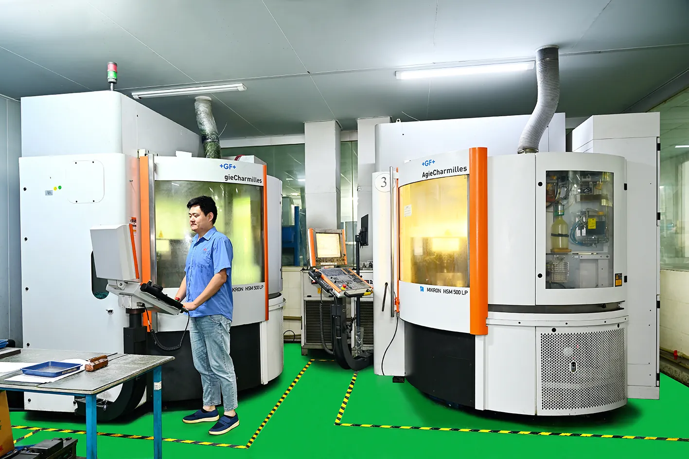
High-speed CNC centers machine H13 in its hardened state. DieStrike runs Mikron high-speed machines for this class of work, holding ±0.005 mm standard and ±0.002 mm on critical insert features.
S136 and 420 for corrosion and clarity
S136 at 48-52 HRC typical is the standard for corrosive resins and optical parts. Its chromium content resists attack from PVC, flame-retardant compounds, and other aggressive melts.
420 stainless serves similar duty at 45-52 HRC typical, often where polish matters more than toughness. Transparent parts need an insert that holds an optical finish without pitting, which is an S136 specialty.
BeCu for hot spots
Beryllium copper conducts roughly 3-10× the heat of tool steel, typical by alloy. That makes it the standard fix for hot spots that drilled channels cannot reach.
A BeCu plug sits behind a thin cavity wall and pulls heat into a nearby channel. The plug is small, 10-30 mm typical, and replaces a section of steel without re-routing the whole cooling circuit.
Carbide for wear
Tungsten carbide at 88-93 HRA typical is the hardest common insert material. It resists abrasive wear from glass-filled and mineral-filled resins better than any steel.
Carbide is brittle, so it appears as small inserts, gate inserts, and wear pads, never as a full cavity. The payoff is life: a carbide gate insert typically outlasts a steel gate by several multiples on abrasive resins.
Verify the heat treatment before assembly
Hardness claims are only as good as the batch. A certificate says what the steel should be; a hardness test says what this insert is.
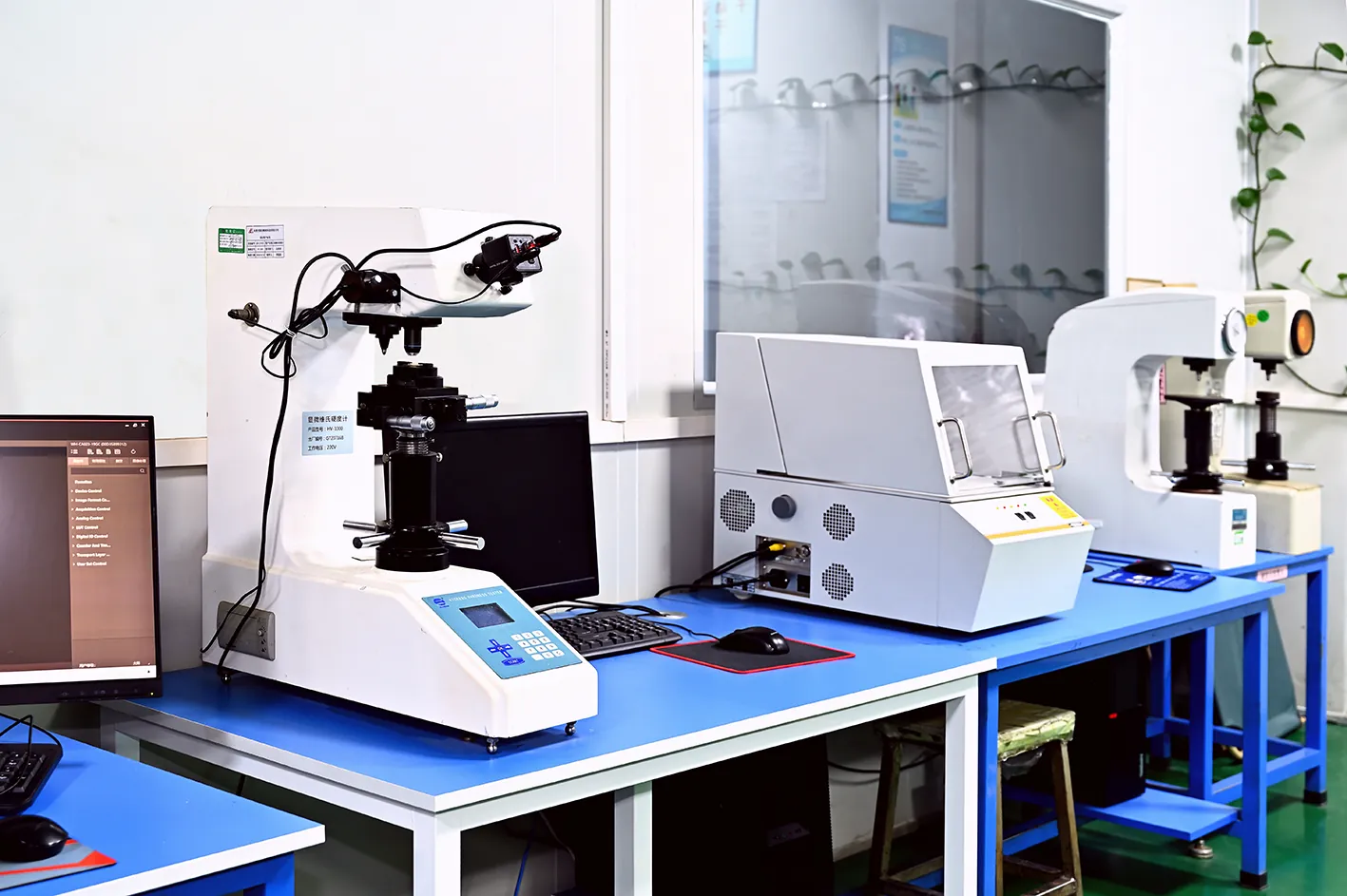
DieStrike verifies hardness on every heat-treatment batch with Vickers and Rockwell testing. A core insert at 46 HRC instead of 50 behaves differently under melt pressure, and the test catches it before the mold ships.
Fit and Tolerance in the Pocket
The fit between insert and pocket carries the mold's precision. Too loose, and the insert shifts under pressure. Too tight, and it will not seat, or it binds when the mold reaches operating temperature.
Small inserts up to about 100 mm typical run an interference fit of 0.005-0.015 mm. That is enough to hold position without pressing the insert in. The pocket is machined to ±0.005 mm, and the insert is matched to it at assembly.
Cylindrical inserts and bushings use ISO fits. H7/k6 is typical: the hole holds H7, the insert holds k6, giving a light press or transition fit that locates the insert positively.
Large inserts above 200 mm typical need room to grow. Steel expands roughly 11.5 µm per meter per degree Celsius, so a 250 mm insert at a 40 °C operating delta grows about 0.1 mm. Large inserts use a sliding fit of 0.02-0.05 mm typical and rely on dowels and screws, not interference, for position.
Shrink-fit assembly is reserved for bushings and small rings. Heat the part to 150-250 °C typical, drop the steel insert in, and let it contract to a true interference fit. The process is fast, and the fit is repeatable.
The pocket floor matters as much as the walls. A floor that is not flat lets the insert rock under pressure. We hold pocket floors flat and parallel to 0.005 mm typical and verify seat contact at assembly.
Verify the fit before the mold leaves the floor
Fit verification is a measurement, not a feel. We check the insert and pocket on a CMM at 20 °C, the ISO 1 reference temperature. That way the numbers mean the same thing on your floor and ours.

Zeiss CMM machines verify pocket position, insert size, and the assembled fit. Every critical insert ships with the CMM record, so a future replacement can be cut to match without guesswork.
Locating, Alignment, and Holding Screws
Fit controls position; locating controls repeatability. Every insert needs a positive location that survives disassembly and reassembly, plus a clamp that holds it against molding forces.
Two dowel pins are the standard locator. They run 6-12 mm diameter typical for small inserts, are ground to H7 tolerance, and are offset so the insert cannot assemble 180° out. Dowel holes are jig-ground after heat treatment, so the hardened insert and its holes agree.
Large rectangular inserts use keys or side rails instead of dowels. Keys seat in ground slots and locate the insert in two directions while leaving the third free for thermal growth.
Holding screws pull the insert into its seat. Three to four socket-head cap screws of M6-M10 typical hold a small- to medium-sized insert, and the count scales with size and expected melt pressure. Screws are countersunk or placed outside the part footprint so they never mark the molded part.
Thermal growth is why inserts are not bolted rigid everywhere. A 200 mm insert expands roughly 0.09 mm over a 40 °C delta, so the retention pattern must let it grow toward the free direction. Rigid clamping at both ends turns expansion into stress and, eventually, a shifted insert. Our mold base specification guide applies the same logic to plates and alignment systems.
Cooling the Insert: Channels and BeCu Plugs
An insert is a heat exchanger before it is a shape. Cooling design decides cycle time and part dimensions, and inserts complicate cooling because the pocket interrupts the channel path.
Drilled channels in the plate behind the insert are the baseline. They run 6-8 mm typical diameter and pass within 8-15 mm typical of the cavity face. The insert transfers heat to the plate, and the plate carries it away.
Core inserts need internal cooling because plastic surrounds them. Baffles and bubblers push coolant up small drilled holes inside the core; water flows in, hits the baffle, and returns up the other side. Core cooling channels run 4-8 mm typical on small inserts.
BeCu plugs fill the gap where a channel cannot go. A plug of 10-30 mm typical sits under a thin wall and conducts heat sideways to a nearby channel. The effect is a local cooling improvement of 20-40% typical on the plug's zone, without re-cutting the plate.
Balanced cooling matters more than aggressive cooling. A 5 °C variation between cavities shows up as dimensional scatter between parts from the same mold. We verify cooling circuits at trial and balance flow so every cavity sees the same temperature.
Surface Finish and Venting Through Inserts
Finish requirements follow insert function, not fashion. A cavity face that must release a clear part needs a mirror; a shut-off that must not gall needs controlled roughness.
High-gloss cavity inserts finish toward the SPI A-1/A-2 band, roughly Ra 0.012-0.05 µm typical by published SPI finish grades. Textured inserts are media-blasted or etched to the specified texture, then sealed so the texture survives molding and cleaning.
Shut-off surfaces run rougher on purpose. A shut-off at Ra 0.4-0.8 µm typical resists galling and holds lubricant, while a mirror shut-off can seize under pressure. The finish spec belongs on the insert drawing, not in an email.
Venting is where inserts earn their keep. Air trapped in a cavity burns plastic and causes short shots. A vent depth of 0.01-0.03 mm typical lets air escape without letting melt flash, and vent lands run 5-10 mm typical before opening to atmosphere.
Vent inserts and EDM'd gas paths
When the parting line cannot vent a deep rib or boss, a vent insert carries the path. The insert sits at the deepest fill point, and its ground face provides the vent gap.
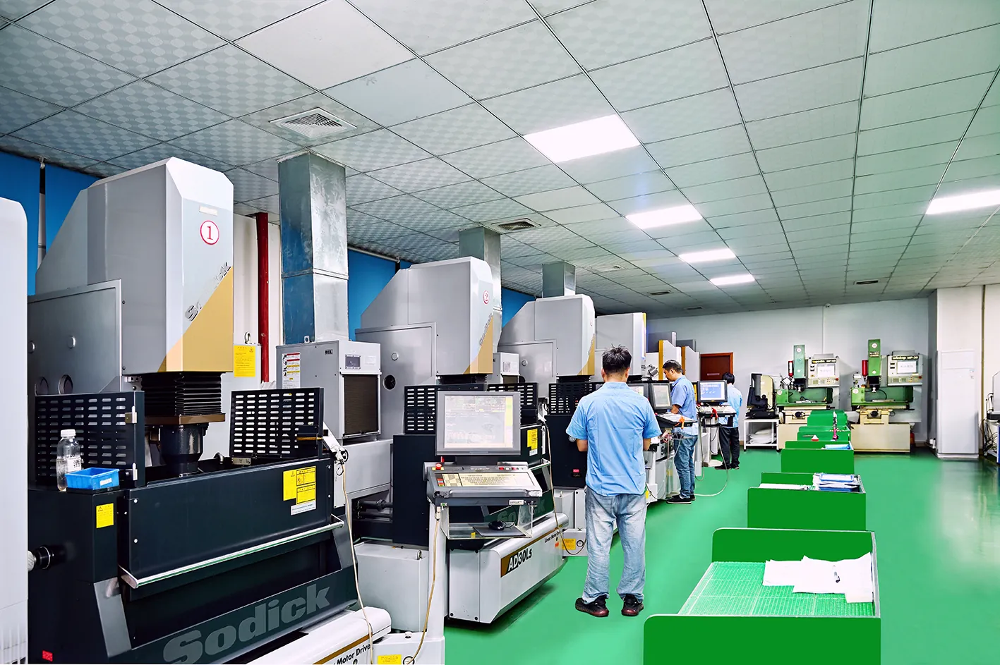
Sinker EDM machines vent inserts and gas paths into hardened steel with repeatable depth control. DieStrike runs Sodick EDM machines for this work, so vent depth holds across every insert in the set.
Maintenance, Replacement, and Change Time
The value of an insert is a fast, predictable change. A standardized insert change runs 1-2 hours typical for small inserts: mold out, screws out, insert out, new insert in, mold back to the press.
That target only holds if the spare matches. A replacement insert cut to the original CMM data seats without hand-fitting. Hand-fitting on the floor turns a 2-hour change into an 8-hour event, which is exactly the downtime a specification sheet should prevent.
Stock spares for the wear items. Gate inserts, wear pads, and the most stressed core inserts are cheap compared with press time. DieStrike ships standard components in 3-7 days when a spare is needed.
Track shot counts and inspect on schedule. A gate insert that erodes predictably at 300,000 shots typical should be measured at 250,000, not discovered at 310,000. Part dimension trends catch insert wear before the part fails.
Reconditioning insert seats
After many changes, the seat itself wears. A pocket floor that has been re-ground twice holds the insert differently than a fresh one.
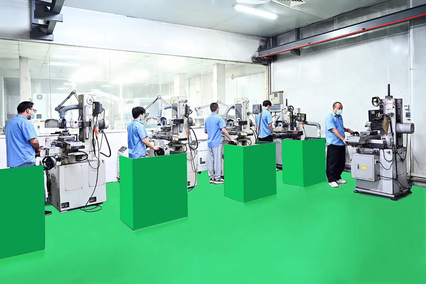
Surface grinders recondition insert seats flat and parallel, restoring the pocket to the original 0.005 mm flatness target. The interval depends on change frequency; molds changed weekly typically need seat attention annually.
Interchangeability, Documentation, and DFM
An insert is only useful if the next one fits the same pocket. Interchangeability is a manufacturing standard, not a hope: every insert in a set must match the pocket, the dowels, and the part datum.
Multi-cavity molds demand matched inserts. Eight cavities from the same program should measure within 0.005 mm typical of each other at critical features. Any cavity then produces a part inside the same tolerance band.
Replaceable inserts carry design iterations. A bridge mold with planned revisions uses inserts that swap when the part changes, while the base, the pocket, and the cooling stay. The revised insert reuses the same dowel positions and screw pattern, which keeps revision cost and risk low. For the same reason, printed inserts change the iteration economics entirely, and our 3D printed vs machined inserts guide shows when that route wins.
Documentation makes interchangeability real. Every insert needs a number, a drawing, and a material record that travels with the mold. Insert C2-03 means cavity two, core insert three, on the drawing and in the maintenance file.
The drawing carries the steel grade, heat treatment, finish, and pocket fit call-out. Material certificates and hardness reports accompany the insert; under IATF 16949 the chain is auditable from steel certificate to CMM report.
DFM review covers the pocket itself. Pocket corners need a radius of 1-3 mm typical, never a sharp internal corner that concentrates stress. Pocket walls carry 0.5-1° draft typical so the insert releases and re-seats without binding.
Pocket depth is set so the insert seats on the floor, not on the screws. A screw that pulls the insert down while the floor carries load is a stable joint. A screw that fights the floor fails at the first temperature swing. DieStrike's free 24-hour DFM review flags fit class, steel, radii, venting, and cooling before steel is cut.
FAQ: Mold Insert Specification
When should I use a mold insert instead of a solid cavity?
Use inserts for wear zones, multi-material molding, hard-to-machine geometry, cost reduction, or planned design changes. If the feature will outlive the mold and never change, a solid cavity is simpler and often cheaper.
What is the standard fit for an insert in its pocket?
Small inserts typically run 0.005-0.015 mm interference. Cylindrical inserts use ISO fits such as H7/k6. Large inserts above 200 mm use a sliding fit of 0.02-0.05 mm typical to allow thermal growth.
What steel should my core insert be?
H13 at 44-52 HRC typical for hot resins and high cycle counts. S136 for corrosion or clarity, and P20 or 718H for prototypes and low-volume runs. Melt temperature and cycle count decide, not preference.
How long does an insert change take?
1-2 hours typical for small inserts when the spare matches the original CMM data. Hand-fitting on the floor can stretch that to a full day, so documentation matters as much as the steel.
Do inserts hurt cooling performance?
Not if the pocket is designed for it. Channels behind the insert, baffles inside cores, and BeCu plugs under hot spots keep heat moving. A 5 °C cavity-to-cavity variation is the warning sign to balance flow.
Can I reuse inserts across design iterations?
Yes, when the base, pocket, dowels, and screw pattern stay fixed. A revised insert seats in the original pocket, which cuts revision cost roughly in half typical compared with re-cutting a solid cavity.
The Bottom Line
A wrong insert spec does not fail at approval. It fails at 200,000 shots, or on a Friday shift change, when the mold comes down and the spare does not fit. That is the downtime a specification sheet exists to prevent.
Fit, steel, and design prevent that downtime. A pocket fit holds position. A steel grade survives the service. A design lets the insert change in hours. DieStrike builds and documents inserts to those standards, and our custom mold insert page lists the pocket, fit, and steel options we machine in-house.
NEXT STEP
Ready to Start Your Mold?
Send us your element dimensions or part numbers — our team responds within 24 hours with pricing and lead time.

Written by
Ray ChanMold Buyer's Guide Author · Precision Mold Manufacturing Specialist. Ray helps global importers, distributors and OEMs source factory-direct molds and mold parts.