
3D Printed Inserts vs Machined Inserts: When Each Wins
Table of Contents
A printed insert failure is not a line stop. It is a mold teardown. One automotive connector program lost 14 days when a printed beryllium-copper core cracked at shot 2,100, mid-pilot. The mold came off the press, the cavity stack came apart, and the launch plan was rebuilt around a machined steel replacement. The lesson was that the insert had been chosen for the wrong job.
This guide separates the two routes with real numbers. You will see the materials that actually get printed. You will see the surface and tolerance limits of as-printed steel. And you will see the cycle-time lever that makes conformal cooling worth the premium. You will also see the worked cost arithmetic that decides when a machined insert is the cheaper path.
DieStrike builds this comparison from daily shop-floor data. We are an IATF 16949 precision mold maker running 120+ machines. We hold critical mold dimensions to ±0.005mm, with precision work at ±0.002mm, and heat-treat cavity steel to HRC 62. Prototype molds ship in 2-5 weeks, and standard components such as ejector pins and core pins ship in 3-7 days. Customers including TE Connectivity, Amphenol, Luxshare, and Dongshan Precision run programs on our tooling.
The Snapshot
- AM insert cost: $500-3,000+ typical; machined insert: $300-1,500 typical for small inserts.
- Lead time: AM prototype inserts 3-7 days typical; machined inserts 1-3 weeks typical.
- Conformal cooling in a printed insert cuts cycle time 15-40% typical.
- Tolerance: AM as-printed ±0.1-0.3mm typical; machined ±0.005mm achievable.
- Surface: AM as-printed Ra 6-12 µm typical; machined Ra 0.4-1.6 µm, so finish machining is mandatory.
What Is a 3D Printed Mold Insert?
A mold insert is a removable cavity or core block that sits in the mold base and forms the part surface. In conventional tooling it is machined from a solid block of steel or aluminum. In additive manufacturing, the same block is built layer by layer from metal powder.
The process has three common names. Laser powder bed fusion (LPBF) is the technical term. Selective laser melting (SLM) and direct metal laser sintering (DMLS) are the commercial names for the same family of machines. A laser fuses powder in layers 20-60 µm thick typical, building the geometry from the CAD model without a toolpath for the internal features.
Do not confuse this with polymer printing. A printed polymer insert survives a few hundred low-pressure shots at best. A printed metal insert is a production-grade steel part, dense enough to hold injection pressure and heat. The density of a well-tuned LPBF part runs 99.5% or higher typical, close enough to wrought material for most mold service.
Printed metal inserts sit in a specific lane of tooling strategy. They appear in bridge tools, pilot molds, and low-volume production where the part geometry, the schedule, or the cooling requirement justifies them. They also appear in full production tools for one specific feature: conformal cooling channels that no drill can reach.
AM Insert Materials: What Actually Gets Printed
Not every tool steel prints well. Powder must flow, melt, and solidify without cracking under thermal stress. The material shortlist that mold shops actually use is short, and each entry has a defined role.
Maraging steel 18Ni300 is the workhorse. It prints with low distortion, ages to a useful hardness, and holds dimension well through heat treatment. After aging, a printed 18Ni300 insert runs HRC 45-54 typical. That is below production cavity steel, so it suits bridge runs and low-volume parts, not million-shot programs.
H13-class hot-work steel is the high-temperature option. It keeps strength at elevated mold temperatures, which matters for high-cavity-temperature resins. Printed H13-class inserts reach HRC 44-52 typical after tempering. The same grade is a standard die steel in machined tooling, so the material behavior is a known quantity.
Beryllium copper (CuBe) is the thermal specialist. Its thermal conductivity runs roughly 100-130 W/m·K typical, several times that of tool steel. A printed CuBe core with internal channels pulls heat out of a deep pocket that steel cannot reach. It costs more per kilogram than steel powder, and the printed insert price reflects it.
Tool steel variants print when the volume justifies them. P20-class and H11 powders exist, aimed at pre-hardened or hot-work service. The trade is always the same. Powder cost per kilogram is several times wrought bar. A printed insert in the $500-3,000+ range typical only makes sense when geometry, lead time, or cooling justifies the premium.
As-Printed Limits: Density, Hardness, Surface, Tolerance
Additive manufacturing delivers geometry, not finish. The parts that come off the printer are dense and strong, but they are also rough, undersized, and dimensionally loose. Knowing those limits up front is what separates a planned process from a surprise.
Density. A tuned LPBF process holds 99.5%+ density typical. Porosity exists but stays low, and mechanical properties approach wrought values in the build direction. Part orientation still matters. Properties are near-isotropic after heat treatment, but a part designed for the wrong orientation can show weakness under fatigue.
Hardness. As-printed maraging steel is soft, around HRC 30-38 typical. Aging brings it to HRC 45-54 typical. Printed H13-class steel tempers to HRC 44-52 typical. Neither reaches the HRC 58-62 of hardened machined cavity steel, which is the durability gap that limits printed inserts to shorter runs.
Surface finish. The as-printed surface runs Ra 6-12 µm typical. A machined and polished cavity runs Ra 0.4-1.6 µm, and cosmetic grades go lower. You cannot mold a visible surface directly on a printed wall. Every printed insert that forms a visible or sealing surface needs secondary work.
Tolerance. As-printed dimensions hold ±0.1-0.3mm typical. That is fine for internal channel placement, not fine for shutoff faces or part-forming details. The engineering answer is simple. Print the near-net shape, then machine the critical faces.
Finish Machining, EDM, and Polish Are Still Required
The printed insert is a near-net blank. The faces that form the part, seal the parting line, or locate in the mold base are machined after printing. DieStrike treats every printed insert like wrought stock. Final geometry comes off a spindle, an EDM machine, or a grinder, not off the printer.
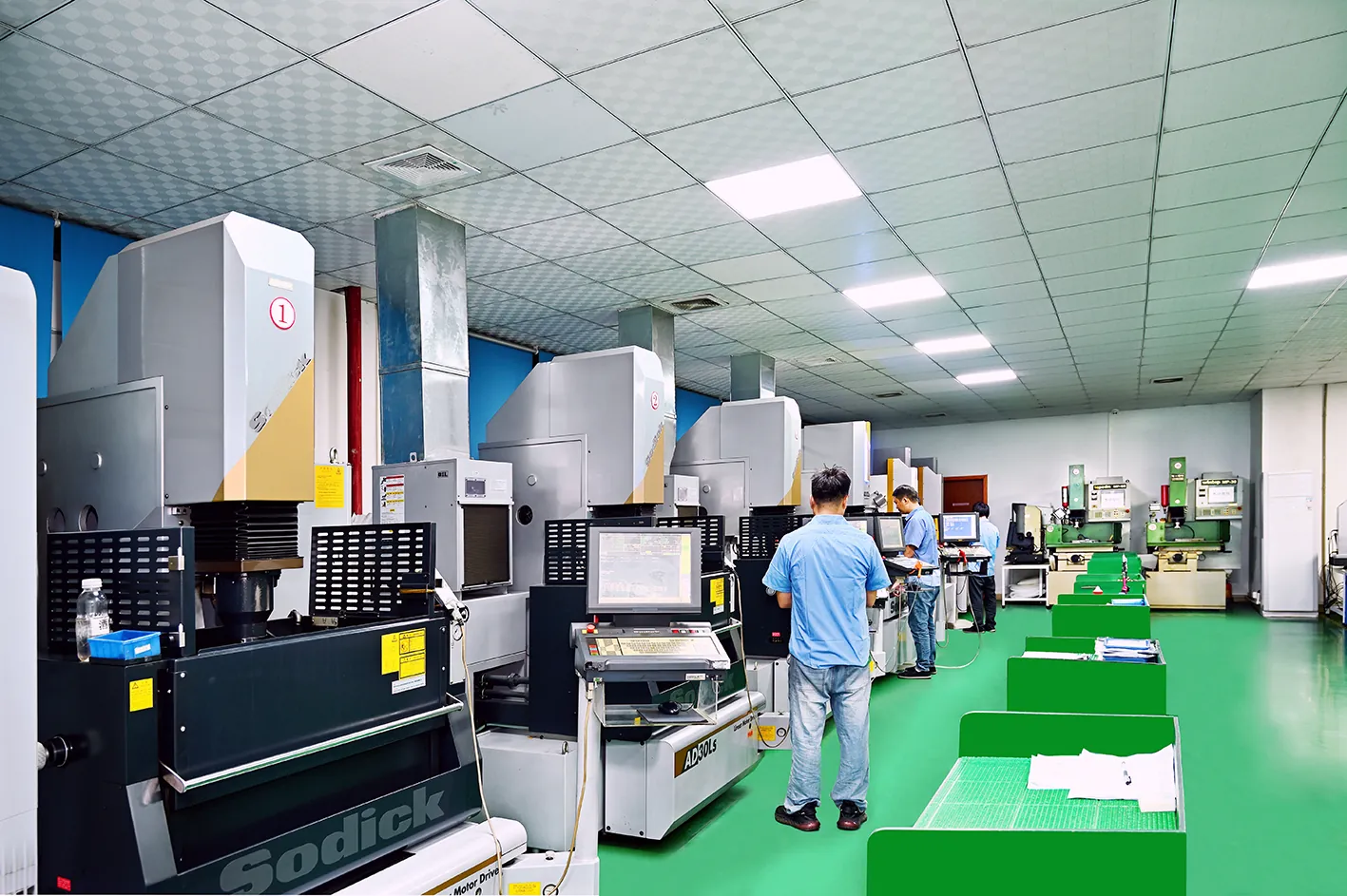
Machining a printed insert follows a fixed sequence. Stress-relieve or age the part first, so it does not move on the machine. Rough the critical faces, then finish them to the drawing tolerance. Use EDM for sharp internal corners and fine ribs. Polish the part-forming surfaces to the SPI grade the part demands.
The result is a hybrid manufacturing story. The printer makes the geometry a drill cannot. The machine shop makes the accuracy a printer cannot. Only when both steps happen does the insert earn its place in the mold.
When AM Wins: Conformal Cooling
Conformal cooling is the strongest reason to print an insert. A conventional cooling channel is straight because it is drilled. A conformal channel follows the contour of the cavity, hugging the part at a constant distance. That single difference changes the thermal behavior of the mold.
The numbers are consistent across published case studies. Conformal cooling in a printed insert cuts cycle time 15-40% typical versus straight-drilled channels on the same part. The spread depends on part geometry, wall thickness, and resin. Deep pockets and thick bosses show the biggest gains, because those are the regions a straight channel cannot reach.
The physics is simple. Cooling time is often 50-70% of a molding cycle typical. Shorten the cooling time and you shorten the cycle, and cycle time is money. A 20% cycle cut on a 30-second cycle saves 6 seconds per shot. That is roughly 13,000 more shots per year on a 24-hour, 7-day schedule.
Cycle Time: A 15-40% Typical Reduction
Cycle time improvement is the headline number, and it compounds over a run. On a bridge tool running 20,000 shots, a 20% cycle reduction pays the insert premium several times over, before you count the part-quality benefits.

Conformal cooling also makes the mold run cooler at the same cycle. A channel that follows the cavity pulls heat from exactly where the melt is thickest. That lowers the average mold temperature and the part ejection temperature, without pushing the cooling water to unsafe flow rates.
The same geometry changes the part itself. Uniform cooling means uniform shrinkage, which means flatter parts and fewer warped features. Teams chasing flatness on large thin panels often reach for conformal cooling before they reach for a stiffer frame.
The Part-Quality Argument
Uneven cooling shows up on the part long before the cycle timer does. Differential shrinkage warps ribs, sinks thick bosses, and distorts press-fit diameters. Conformal channels correct the temperature field, and the part corrects with it.
Our five mold cooling channel design tips cover the straight-channel rules that still govern most tools. Printed inserts are the exception lane in that guide. The exception pays off when a boss, a deep rib, or a thick wall dominates the cooling time.
When AM Wins: Complex Internal Geometry
Some geometry cannot be machined at all. An internal channel that bends around an ejector passage is impossible with a drill. So is a lattice that lightens a core, or a vent path that follows a parting line. Additive manufacturing is not faster or cheaper in these cases. It is the only option.
Cooling right at the cavity. A beryllium-copper core with conformal channels pulls heat from the deepest pocket in the tool. The same feature in wrought material would need a machined core plus a separate cooling insert, more parts, more joints, and more leak paths. The printed version is one piece.
Conformal channels for cores and slides. Cores and slides are the hardest parts to cool, because they are surrounded by hot melt on three or four sides. A printed steel core with an internal channel that follows its own contour keeps the steel temperature under control where a drilled core runs hot.
Venting and gas paths. Printed porous sections or printed vent paths evacuate trapped gas at the last point of fill. Gas traps cause burn marks and short shots, and a printed vent path can remove the defect without adding parting-line vents.
Weight and thermal management. A lattice interior keeps the insert light for handling while printed channels carry coolant. This matters for large inserts where thermal mass works against the process. Less steel to heat means faster startup and a more responsive mold.
The rule of thumb is direct. If the cooling or venting geometry requires more than two drilled channels or a separate insert, the printed route earns a serious quote. Compare the printed one-piece insert against the machined assembly, not against a simple drilled block.
When Machined Inserts Win
Machining wins more often than printing, and it wins for reasons that have not changed in decades. Wrought steel is cheap, accurate, and repeatable. For simple geometry at any volume above a bridge run, a machined insert is the right answer.
Simple Geometry and Tight Tolerances
A machined insert starts as a solid block, so there is no internal geometry to justify the print. Straight cooling channels work fine when the cavity is shallow and the walls are even. The machining route delivers the tightest numbers available in mold making.
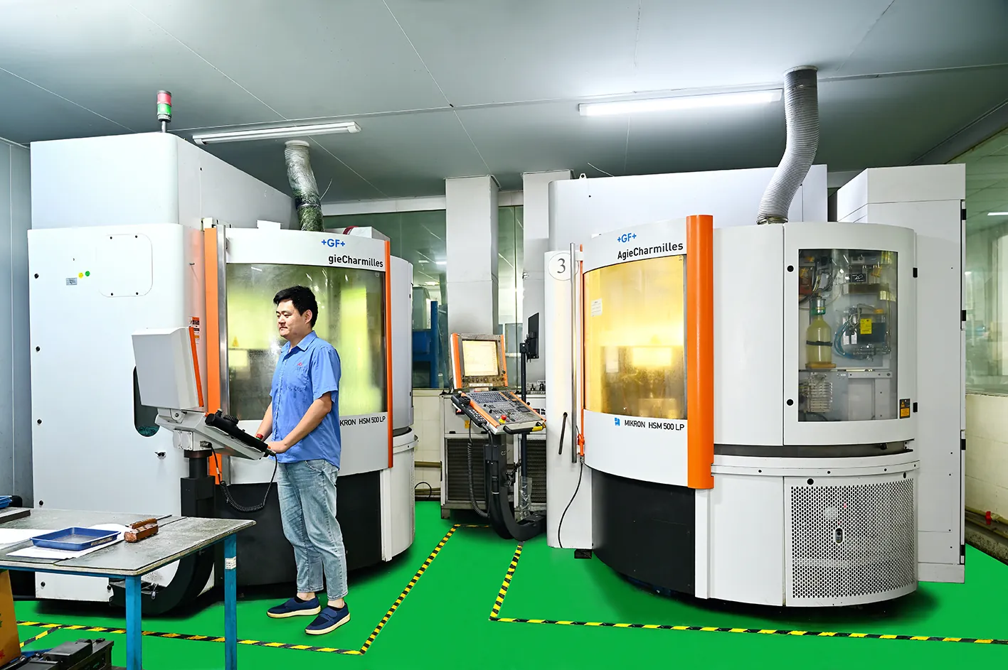
DieStrike holds critical mold dimensions to ±0.005mm, with precision work at ±0.002mm. Mating surfaces, shutoffs, and press-fit diameters all live in this range. A printed insert needs post-machining to reach it, and once the faces are machined anyway, the print only carries value if the internal geometry does.
Wrought steel also has no porosity story to manage. A machined cavity from S136, SKD11, or H13 is fully dense by definition. Polishing reaches SPI A-2 mirror grades, and the finish holds for the life of the tool. Our precision CNC machining guide details the process windows behind those numbers.
Long-Run Stability and Volume Economics
Hardened machined steel outlasts printed steel by an order of magnitude. Cavity steel at HRC 58-62 with wear-resistant coating survives 100,000 to 1,000,000+ shots. A printed 18Ni300 insert at HRC 45-54 typical is a bridge part, not a production part.
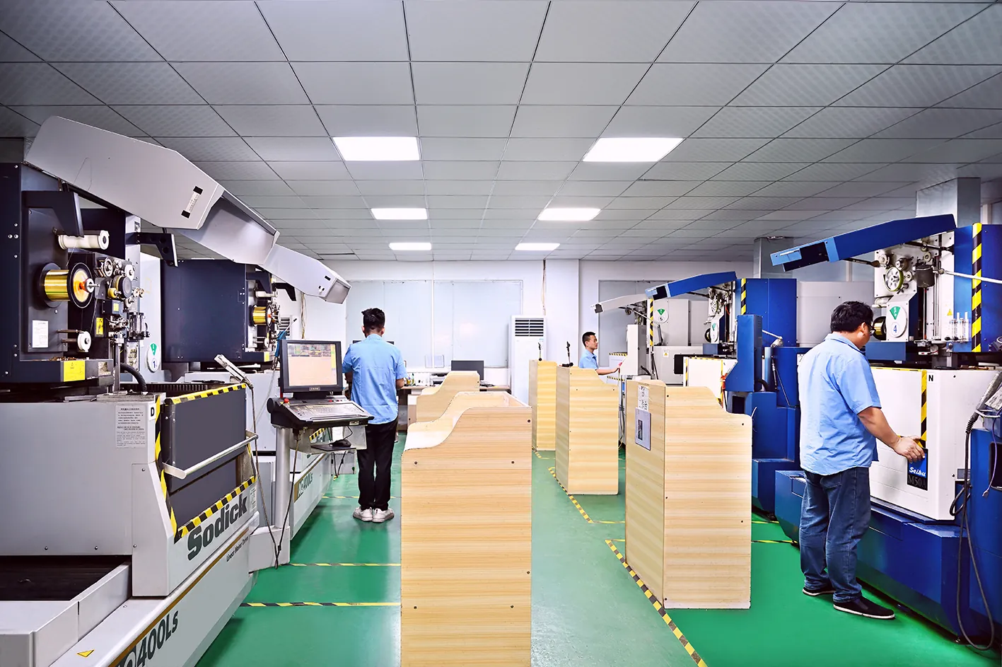
The unit cost curve decides the rest. A machined insert for a simple cavity costs $300-1,500 typical, and a 100,000-shot tool amortizes that cost into fractions of a cent per part. Add the absence of powder premiums, heat-treatment surprises, and porosity risk, and machining is the default for anything that resembles a normal cavity.
Machined inserts also iterate predictably. A re-cut on a machined block follows a known toolpath and a known schedule. A printed insert redesign means a new print, a new heat treat, and a new qualification cycle. When the geometry is simple, the machined route is faster to revise in practice.
AM Insert vs Machined Insert: Side-by-Side
The table below compresses both routes into a spec sheet. Read it against your own part, resin, and forecast, not against a generic checklist.
| Dimension | AM insert | Machined insert |
|---|---|---|
| Typical insert cost | $500-3,000+ | $300-1,500 (small inserts) |
| Lead time | 3-7 days typical | 1-3 weeks typical |
| As-built tolerance | ±0.1-0.3mm typical as-printed | ±0.005mm achievable |
| Surface finish | Ra 6-12 µm as-printed | Ra 0.4-1.6 µm machined |
| Hardness after heat treat | HRC 45-54 typical | HRC 48-62 typical |
| Density | 99.5%+ typical | 100% wrought |
| Cooling channels | Conformal, built-in | Straight drilled only |
| Cycle time impact | 15-40% reduction typical | Baseline |
| Typical cavity life | 1,000-20,000 shots typical | 100,000-1,000,000+ shots |
| Materials | 18Ni300, H13-class, CuBe, tool steel powders | P20, S136, SKD11, H13, 7075 aluminum |
| Best for | Conformal cooling, complex internal geometry, fast delivery | Tight tolerances, long runs, cosmetic surfaces |
← swipe to scroll →
Values are typical published figures for small mold inserts; verify against your geometry, resin, and mold builder.
The pattern is consistent. AM wins on cooling, geometry, and speed. Machining wins on tolerance, life, and unit cost. The decision hinges on which of those four axes your program cannot compromise.
Cost and Lead Time: The Arithmetic
Money and schedule are where the two routes separate most clearly. Work one bridge-tool example and the decision rule appears.
Take a 5,000-shot bridge tool for a connector housing with a thick boss. The printed insert route costs $1,800 typical for the printed and finished insert, and lands in 6 days typical. The machined insert route costs $1,200 typical and lands in 2 weeks typical. On price and schedule alone, the machined insert wins.
Now add the cycle. The boss dominates cooling, and the printed insert cuts cycle time 20% typical. At $60 per hour of press time, a 20% cut on a 40-second cycle saves about $27 per 1,000 shots. That is roughly $135 across 5,000 shots. The printed insert still costs more, but the gap closes.
At 20,000 shots the arithmetic flips. The cycle saving compounds to about $540 typical, the part-quality gains reduce scrap, and the printed insert pays back its premium. Below roughly 5,000 shots, a machined insert is usually cheaper even with conformal cooling. Above roughly 20,000 shots, the printed insert earns its cost on cycle alone.
Lead time follows a similar pattern. Printed prototype inserts ship in 3-7 days typical. Machined inserts ship in 1-3 weeks typical. DieStrike compresses the machined route with a 120+ machine fleet, and prototype molds ship in 2-5 weeks with standard components in 3-7 days. A printed insert is still the faster path when the schedule is measured in days.
The Hybrid Approach: Printed Core, Machined Cavity
The strongest designs do not choose one route. They combine them. A printed core carries the conformal channels, and a machined cavity forms the visible surface and holds the shutoffs. Each part does what it does best.
How the Hybrid Insert Is Built
The hybrid sequence follows the same discipline as a fully machined insert, with one added step. Print the core with internal conformal channels, age or stress-relieve it, then machine every functional face to the drawing tolerance.
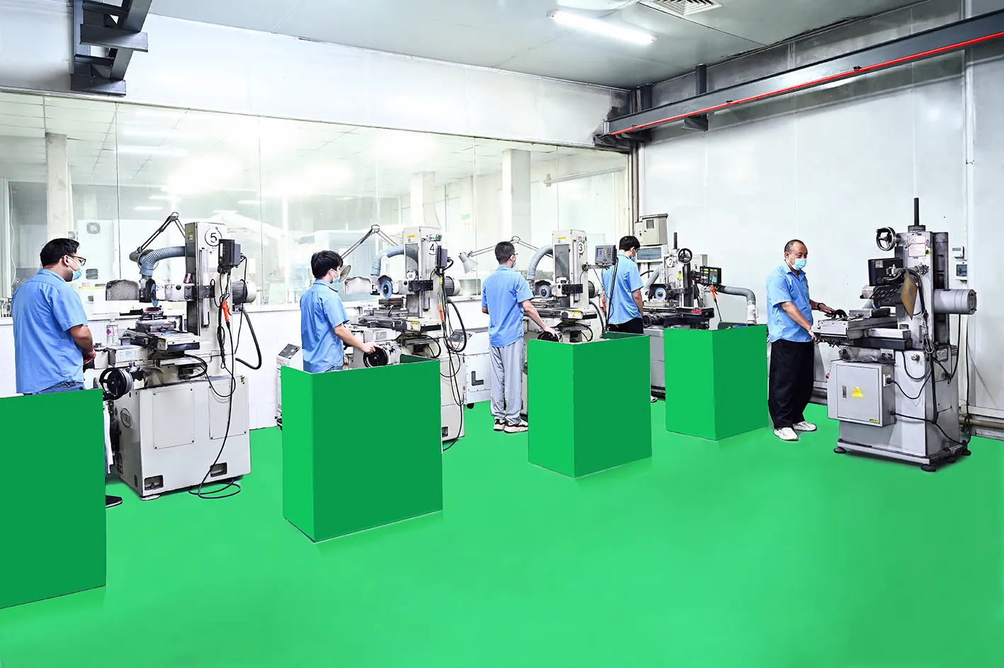
A typical hybrid stack pairs a printed CuBe or 18Ni300 core with a machined S136 or SKD11 cavity. The printed core pulls heat from the deep pocket. The machined cavity forms the cosmetic surface, holds the tight tolerance, and seals the parting line. The mold gets both the cooling and the finish.
Hybrid tooling also derisks the schedule. If the printed core fails in trial, only the core is reprinted and remachined, typically inside a week. The machined cavity stays in place, and the mold returns to the press faster than a full teardown and rebuild.
Ask your mold builder for the hybrid quote before you commit to either extreme. On many bridge tools, the hybrid lands within a few hundred dollars of the all-machined route. It still delivers most of the cycle benefit of full AM.
Quality and Verification: What the Shop Checks
A printed insert earns its place only after verification. The shop routine matters more than the print technology, because every printed part carries porosity, distortion, and surface risk that a wrought block does not.
The Measurement Routine
The verification starts before machining. The as-printed blank is measured against the CAD model to confirm the internal channels are in place and clear. Then the machined insert is verified exactly like a conventional insert, against the drawing, not against the print intent.

DieStrike runs this verification on a Zeiss CMM, with critical dimensions reported at ±0.005mm and precision features at ±0.002mm. Hardness is checked after heat treatment, and porosity is checked on any section that carries pressure. The first-article report documents every number the customer signs off.
Trial shots are the final gate. The mold runs until the cavity temperature, cycle time, and part dimensions stabilize, and the insert is inspected again for movement or wear. A printed insert that moves in trial is caught here, before production, not at shot 2,100.
This is the discipline our IATF 16949 and ISO 9001 systems enforce. With 120+ machines and customers like TE Connectivity, Amphenol, Luxshare, and Dongshan Precision, the verification bar is set by the supply chain. The same bar applies to AM inserts and machined inserts alike.
FAQ: 3D Printed vs Machined Inserts
Q1. Can a 3D printed insert match a machined insert's tolerance?
Not as-printed. A printed insert holds ±0.1-0.3mm typical, while a machined insert holds ±0.005mm. If the printed insert's critical faces are machined after printing, it can meet the same drawing tolerance. The internal printed geometry keeps its looser tolerance, which is acceptable for channels and vents.
Q2. Do printed inserts need finishing before molding?
Yes, on every functional surface. As-printed surface finish runs Ra 6-12 µm typical, versus Ra 0.4-1.6 µm for machined surfaces. Part-forming faces need machining, EDM, and polish to the required SPI grade. A printed insert is a near-net blank, not a finished cavity.
Q3. How many shots can a printed metal insert survive?
Typical published figures run 1,000-20,000 shots for maraging steel and H13-class inserts at HRC 45-54 typical. That suits bridge and low-volume production. Production tools needing 100,000+ shots should use hardened machined steel at HRC 58-62.
Q4. When does a printed insert actually save money?
When conformal cooling shortens the cycle. A 15-40% typical cycle reduction compounds across the run, and the payback usually lands between 5,000 and 20,000 shots. Below that volume, the machined insert's lower cost wins. Complex geometry that cannot be drilled also justifies the print.
Q5. What is a hybrid insert?
A hybrid insert pairs a printed core with a machined cavity. The printed core carries conformal cooling channels. The machined cavity forms the visible surface, holds the tight tolerance, and seals the parting line. It delivers most of the cycle benefit of full AM at a lower cost.
Q6. Does DieStrike make printed inserts?
DieStrike machines every insert to final geometry in-house, working with qualified AM partners for the print step. Printed blanks arrive at our shop. They go through heat treatment, machining, EDM, polishing, and CMM verification on the same 120+ machine line as conventional inserts.
The Bottom Line
Choose the insert route by answering four questions. Does the cooling geometry need to be conformal? Is the internal geometry impossible to drill? Is the schedule measured in days or weeks? Is the run above or below roughly 20,000 shots?
Printed inserts win when conformal cooling or impossible internal geometry is on the table, and when the run stays in the bridge and low-volume range. Machined inserts win on simple geometry, tight tolerances, cosmetic surfaces, and long production life. The hybrid route captures most of the cooling benefit at a machined price.
The failure at shot 2,100 did not end that connector program. It ended the use of a printed core where a machined steel core belonged. The reverse error is just as common. Teams machine a straight-channel insert for a thick-boss part and leave 20% of the cycle on the table, every single shot.
If your program is on a tight clock, our guide to prototyping molds in two weeks walks through the scheduling side of the same decision. Whether your insert is printed, machined, or both, the geometry should drive the route, and the numbers should drive the geometry.
NEXT STEP
Ready to Start Your Mold?
Send us your element dimensions or part numbers — our team responds within 24 hours with pricing and lead time.

Written by
Ray ChanMold Buyer's Guide Author · Precision Mold Manufacturing Specialist. Ray helps global importers, distributors and OEMs source factory-direct molds and mold parts.