
How to Select Cam Units for Stamping Dies
Table of Contents
A cam slider that fails to retract in 0.2 seconds can scrap a $60,000 progressive die. At 60 SPM the ram completes a full stroke every second, and every cam must be home before the next hit. When one is not, the driver shears the slider body, the punch shatters, and 40 mm of strip jams the feed. Repair typically costs $4,000 to $15,000 plus 1 to 3 weeks of lost output.
Cam units are what let one die do side pierce, side form and side trim without a second press operation. They also add the most common crash mode in stamping: a return system that loses 10% of its force over 400,000 strokes. This guide walks the six inputs that decide the selection, from cam angle and travel ratio to wear plate grade and lubrication interval.
The Snapshot
- Cam angle sets the trade. A 45 degree cam gives 1:1 travel at 100% of ram force, a 30 degree cam gives 1:1.732 travel at 58% of force, and a 60 degree cam gives 0.577 travel at 173% of force.
- Standard cam units cover roughly 3 to 40 kN of working force and 10 to 80 mm of slide travel at $200 to $1,200 each, typical 2026 catalog pricing.
- Return force should be 15 to 20% of the working force, or the slider can hang forward and the next stroke crashes.
- Wear plates run HRC 58 to 62 with 0.02 to 0.05 mm gib clearance, and need lubrication every 5,000 to 10,000 strokes.
- A cam return proximity sensor costs $80 to $250 and stops the press inside one stroke, which is the cheapest die protection available.
Why Cam Units Decide Your Die Layout
A station that pierces a 3 mm hole in a vertical wall cannot be built with a straight punch. The wall faces sideways, so the punch must travel sideways, and the only way to convert ram motion into sideways motion is an inclined driver. That is a cam unit: a driver mounted on one shoe, a slider mounted on the other, and wear surfaces between them.
One cam station typically costs $2,000 to $4,000 of tool build, which sounds expensive until it replaces a secondary press operation. A second operation adds $0.03 to $0.08 per part, plus a transport step and a second fixture. Over 200,000 parts that is $6,000 to $16,000 of pure process cost, so a cam almost always pays back on a program above 100,000 units.
Footprint is the real constraint. A 45 degree aerial cam unit with 25 mm of slide travel measures roughly 100 mm by 150 mm at the base. It stands 60 to 90 mm tall with the driver engaged. Four cam stations consume 60,000 mm2 of die shoe area, which is why cam dies run 350 to 600 mm wide and 800 to 1,500 mm long.
Cam layout also decides station count. Hitting a hole from the side in station 4 of an 8 station die usually removes a downstream station entirely, cutting 12 to 15% of die cost. Injection molds solve the same problem with angle pins and slides, a different mechanism with a different force model, as covered in side action design for injection molds.
DieStrike tooling engineers review cam layouts as part of the standard DFM package, with feedback returned inside 24 hours.
The Three Cam Actions: Pierce, Form and Trim
Cam units do three jobs in stamping dies, and each one sizes the unit differently. The action type sets the working force, the slide travel and the stripping requirement before you ever look at a catalog page.
Cam pierce. A side pierce needs shear force, and shear force follows the perimeter rule: perimeter times thickness times shear strength. A 3 mm round hole through 1.5 mm SPCC with 300 MPa shear strength needs 9.42 mm x 1.5 mm x 300 MPa, which is about 4.2 kN. Add 10 to 15% stripping force and 30% impact allowance, and the cam unit must be rated above 6 kN. Punch geometry for these stations follows the same rules as vertical piercing, covered in perforator selection for stamping dies.
Cam form. Flanging and bending need 10 to 25 mm of slide travel but only 15 to 40% of the pierce force for the same wall. Forming cams usually run 30 to 45 degrees so the ram travel stays inside the press stroke. Springback control adds 1 to 3 degrees of overbend, which the cam slide must deliver as extra travel.
Cam trim. Trimming a side wall or a drawn shell edge needs 8 to 10% of material thickness as punch clearance. A 1.2 mm wall therefore runs 0.10 to 0.12 mm clearance per side. Trim cams see a side thrust that tilts the slider, so they need the heaviest gib support of the three actions.
The single most common selection error is sizing a cam unit by tonnage alone. A 4.2 kN pierce is easy for any catalog unit. But a 25 mm slide travel at a 30 degree angle forces the ram to move 43 mm, and that number decides whether the unit fits the press.

Standard Cam Units vs Custom Cams: The Build or Buy Call
Standard cam units from DME, Fibro, Danly, Dayton and Misumi cover most stamping work. Catalog sizes include 30, 45 and 60 degree drivers, slide travels from 10 to 80 mm, and load ratings from roughly 3 to 40 kN. They ship as a matched set: driver, slider, wear plates, return spring and mounting keys.
Buy standard when four conditions hold. Required slide travel is within 10% of a catalog size. Working force stays under 50% of the rated load. The cam angle matches a catalog option, and the base pattern fits the die shoe. Under those conditions a standard unit costs $200 to $1,200 and arrives in 1 to 2 weeks.
Build custom when the numbers break the catalog. Slide travel above 80 mm, working force above 40 kN, a non-standard angle such as 25 or 50 degrees, or a slider that must be integrated into the die block for rigidity. A custom cam block costs $900 to $3,000 plus 15 to 25 hours of machining and 5 to 10 hours of design time.
Hybrid is the usual answer. Many shops buy a standard slider and machine a custom driver horn to fit the available shut height. That keeps the wear pairs and the return spring as catalog items while solving the space problem, and it drops the custom cost to $400 to $900.
Lead time is a real decision input. Standard die components including punches, spring units, guide posts and cam units ship from DieStrike in 3 to 7 days. Full stamping dies ship in 2 to 5 weeks, so a standard cam unit ordered late rarely delays the build, while a custom block almost always does.
Cam Angle and Travel: The 1:1, 1:1.4 and 1:1.732 Ratios
Cam angle is measured from the horizontal sliding direction, and it fixes the ratio between ram travel and slide travel. The relationship is slide travel equals ram travel divided by the tangent of the cam angle. That single equation drives force, die height and press stroke selection.
A 45 degree cam has a tangent of 1.0, so slide travel equals ram travel, and the ratio is written 1:1. A 35 degree cam has a tangent of 0.700, so it produces 1.43 mm of slide travel per 1 mm of ram travel, written 1:1.4. A 30 degree cam has a tangent of 0.577, giving 1.732 mm of slide travel per 1 mm of ram travel, written 1:1.732.
Force follows the inverse. Work in equals work out, so a 30 degree cam delivers only 58% of the ram force at the slider. A 60 degree cam lifts force by 173% but cuts travel to 0.577 mm per ram mm. Steeper is stronger and shorter, shallower is longer and weaker.
| Cam angle | Travel ratio | Force at slider | Ram travel for 20 mm slide | Typical cam action |
|---|---|---|---|---|
| 30 degrees | 1:1.732 | 58% of ram force | 34.6 mm | Deep flange, long cam form |
| 35 degrees | 1:1.4 | 71% of ram force | 28.6 mm | Cam form, light cam trim |
| 45 degrees | 1:1 | 100% of ram force | 20.0 mm | Cam pierce, cam trim, default choice |
| 50 degrees | 1:0.84 | 119% of ram force | 16.8 mm | Short-stroke notching |
| 60 degrees | 1:0.577 | 173% of ram force | 11.5 mm | Emboss, coining, close-wall pierce |
← swipe to scroll →
Table note: ratios computed as slide travel = ram travel / tan(cam angle). Values are typical for single-slope cam units at 0.05 to 0.12 friction coefficient. Poor lubrication cuts actual output 5 to 15%.
Driver engagement is the hidden check. At a 30 degree angle the driver must contact the slider for at least 15 mm of ram travel before work starts. At 45 degrees, 10 to 12 mm of engagement is enough. Shorter engagement concentrates the load on a few millimetres of wear plate and doubles the local contact pressure.
The last angle check is shut height. A 30 degree cam needing 20 mm of slide travel consumes 34.6 mm of press stroke plus 8 mm of entry and clearance, which is 42.6 mm. A press with a 100 mm stroke and 70 mm of usable travel can carry two such cams in sequence, not four.
Aerial, Lower and Side Cams: Mounting Direction and Die Space
Where the slider sits changes the force path, the return behavior and the space you need. Three mounting families cover almost every stamping application, and each one has a different failure signature.
Aerial cam. The slider is mounted in the upper die and the driver on the lower shoe, so the downstroke drives the slider sideways inside the punch holder. The 60 to 90 mm of added stack height is the price, and gravity assists the return on the upstroke. Aerial cams suit side pierce and side form where the working point sits near the top of the strip plane. They are also the easiest type to inspect and re-lubricate without pulling the die.
Lower cam. The slider sits in the lower die block and the driver hangs from the upper shoe. This is the standard answer when the working point is below the strip plane, such as an upward flange on a drawn shell. The lower position keeps the cam body out of the upper stack, so total die height drops by 40 to 70 mm. The trade-off is access: the slider sits under the strip and offal, so slug clearance must be designed before the pocket is cut.
Side cam. The unit mounts against a vertical die wall with the slider traveling parallel to the strip. Side cams fit narrow dies where an aerial body would not clear the punch holder, typical on strips under 80 mm wide. They carry the lowest stiffness of the three because the die wall must take the full reaction, so die wall thickness under 35 mm needs a bolt-on heel block.
Direction also decides which way the reaction thrust goes. An aerial cam pushes horizontally into the upper shoe, so the punch holder plate must handle the thrust. A lower cam pushes into the die block, so the die wall and the heel are the structure. Sizing the reaction path is a stiffness problem, not a strength problem, and a 0.05 mm deflection at the slider is already 0.05 mm of punch off-position at the strip.

Return Springs vs Nitrogen Gas Springs in Cam Units
The return system is the least glamorous and most consequential part of the cam unit. It must retract the slider, hold it against its stop, and do it inside the upstroke window of every single cycle. Coil die springs and nitrogen gas springs solve that differently, and the difference shows up in force curve, life and maintenance.
A coil return spring delivers force that rises linearly with deflection. A typical spring in a cam application is set at 25 to 35% of its free length at the retracted position, developing 300 to 1,200 N. Life runs 500,000 to 1,000,000 cycles at that deflection, and the force drops as much as 10 to 15% after 300,000 cycles from fatigue and heat set. Coil springs also lose force as they age silently, which is exactly the failure mode that crashes dies.
A nitrogen gas spring holds near-constant force across the stroke, typically within 10 to 15% from full extension to full compression. Catalog cylinders run 150 bar nominal charge, deliver 1,000 to 6,000 N, and last 1,000,000 to 2,000,000 cycles. The flat curve means the retracted holding force equals the force at mid-stroke, so the design check is simpler and the slider never has a weak end of travel.
Sizing rule. Return force should be 15 to 20% of the working force, with a floor set by slider mass. A 6 kg slider with 20 mm of travel that must retract in 0.2 seconds needs roughly 1,200 N of initial force at the moment of reversal. Below that, the slider lags, the driver shoulder hits on the next stroke, and the crash sequence starts. Force curves and cost per 100,000 strokes for both systems are covered in nitrogen gas springs versus coil springs for stamping dies.
| Return system | Force range | Force curve | Typical life | Unit cost and check |
|---|---|---|---|---|
| Coil die spring | 300 to 1,200 N | Rises with deflection | 500k to 1M cycles | $10 to $40, check free length yearly |
| Nitrogen gas spring | 1,000 to 6,000 N | Flat within 10 to 15% | 1M to 2M cycles | $150 to $500, verify charge at 150 bar |
| Mechanical return horn | Not force dependent | Positive, cam driven | Die life | $300 to $700, needs 1:1 up-travel space |
← swipe to scroll →
Table note: typical 2026 catalog values for 25 to 40 mm cam strokes. Coil spring life assumes 25 to 35% deflection of free length. Nitrogen life assumes a 150 bar charge and a 60 to 80 mm/s stroke speed.
The third option deserves more use than it gets. A mechanical return horn drives the slider home through a second inclined face, so the return never depends on stored energy. It costs $300 to $700 extra and needs 1:1 up-travel space, but it removes the entire spring-fatigue failure mode. Dies running above 120 SPM or above 1,000,000 strokes per year should default to mechanical or nitrogen return.
Wear Plates, Gibs and Lubrication for Cam Sliders
Cam wear happens on two surfaces: the inclined driver face that transmits force, and the gib faces that keep the slider aligned. Both need specified hardness, specified clearance and a lubrication plan, or the unit will wear out in under 200,000 strokes.
Material and hardness. Wear plates in SKD11 or 1.2379 hardened to HRC 58 to 62 are the baseline. Bronze-plated plates with graphite plugs run dry at low speed and are the right choice where a grease line cannot reach the slider. Ceramic-coated and PVD-coated plates extend life 2 to 3 times in high-SPM dies but cost 3 to 4 times more. Cam drivers are commonly nitrided to a 0.05 to 0.15 mm case at HRC 58 to 60, which matters on the inclined face where sliding speed and contact pressure peak.
Clearance. Gib clearance of 0.02 to 0.05 mm keeps the slider tracking without binding. Above 0.08 mm the slider rocks under side thrust, which walks the punch off position and cracks small perforators. Below 0.015 mm the unit seizes when the die warms 20 to 30 degrees C above ambient, which is normal after 30 minutes of running.
Lubrication. Contact pressure on a cam wear face typically runs 40 to 100 MPa, and a boundary film of 1 to 3 micrometres is all that separates the surfaces. Grease with extreme-pressure additives applied every 5,000 to 10,000 strokes suits manual maintenance. Dies above 60 SPM should use an automatic lubrication system that meters a few cubic millimetres per stroke. Solid lubricant plates remove the interval problem entirely and are the practical answer for dies that ship to another plant.
Wear limits. Replace wear plates when total thickness loss reaches 0.05 mm on the driver face or the gib. At that point cam angle has shifted by roughly 0.1 degree and slide travel by 0.03 mm. That is already outside the tolerance of a ±0.05 mm hole position. Wear plate replacement is a 2 to 4 hour job in the press and a 1 to 2 day job on the bench.

Cam Force and Press Tonnage: What the Slide Must Absorb
Every cam unit converts vertical ram force into horizontal working force and an equal reaction. Both halves have to be counted, and only one of them shows up in the press tonnage calculation.
Start with the working force. A stack of four side pierce stations at 4.2 kN each needs 16.8 kN at the sliders. On a 45 degree cam that is 16.8 kN of vertical force added to the ram load with no multiplication, because the force ratio is 1:1. On a 30 degree cam the ram must supply 16.8 kN divided by 0.58, which is 29 kN. On a 60 degree cam the ram supplies only 9.7 kN.
Then add the reaction. The horizontal thrust at a cam slider equals the working force, so a 16.8 kN group of pierces pushes 16.8 kN into the die structure. That thrust is absorbed by the die block, heel blocks and dowels, not by the press slide. Contact pressure on a heel face is the check that matters. That load is 84 MPa over a 200 mm2 heel face. The working limit for hardened heel steel at HRC 58 to 62 is 100 to 150 MPa.
The tonnage check. Total die force equals pierce plus form plus strip plus cam vertical components, multiplied by 1.3 for impact. A die running 120 kN of shear, 25 kN of forming and 29 kN of cam load gives 174 kN. After the 1.3 safety factor that is 217 kN, roughly 22 tonnes. That fits a 45 tonne press with margin for the cushion and for strip pull-through.
Two things push cam dies toward a bigger press than the tonnage math suggests. First, off-centre loading: cam stations on one side of the die centreline create a moment that tilts the slide, so keep the resultant within 10% of the press bed centre. Second, energy, not force. A cam that completes 20 mm of travel in the last 15% of the downstroke demands high energy per stroke. At 60 SPM the flywheel energy, not tonnage, sets the limit.
Preventing Die Crash When a Cam Fails to Return
Cam failure follows a predictable sequence, and every step is measurable. Understanding it makes the prevention cheap and the monitoring obvious.
The sequence. A coil return spring loses 10% of its force, so the slider stops 2 mm short of home instead of 0.5 mm. On the next downstroke the driver face strikes the slider shoulder instead of the inclined face, and the contact area drops from 400 mm2 to under 40 mm2. Contact pressure jumps from 60 MPa to over 600 MPa, above the compressive limit of hardened tool steel, so the slider body deforms. The following stroke breaks it, the punch shatters, and offal jams the strip guide. Total elapsed time at 60 SPM: 2 to 3 seconds.
Design defenses. Four measures remove or catch that failure. A mechanical return horn makes retraction positive rather than spring dependent. An anti-crash shoulder with 5 to 8 mm of engagement lets the driver slide over an unretracted slider without shearing it. A nitrogen return spring keeps force flat so there is no weak end. A proximity sensor on the slider confirms home position every stroke.
Monitoring window. At 60 SPM one stroke takes 1.0 second, and the upstroke gives roughly 0.3 seconds of usable return time. A 1 mm sensing distance proximity switch reading the slider home position must produce its signal within 0.2 seconds of bottom dead centre. The press control then has one full stroke to stop, and most mechanical presses stop in 0.5 to 1.5 strokes at that speed. Sensor plus cable plus bracket costs $80 to $250 per cam, against $4,000 to $15,000 for one crash repair and 1 to 3 weeks of downtime.
Maintenance schedule. Check return spring free length at every regrind, which is typically every 0.05 to 0.1 mm of punch wear, or roughly every 80,000 to 150,000 strokes. Replace coil return springs at 250,000 to 500,000 strokes regardless of appearance. Verify nitrogen charge annually and recharge when pressure drops more than 10% below the 150 bar nominal value. Log cam return signal timing, because a drift of 0.03 seconds across 100,000 strokes is the earliest warning available.

Cam Layout in Progressive Dies: Strip Interference
In a progressive die the cam unit shares space with the strip, the feed, the scrap chutes and the pilot pins. Cam layout is therefore a station-level exercise in 3D clearance, not a catalog selection.
Vertical clearance. An aerial cam slider passes 3 to 8 mm above or below the strip plane, depending on the action. The tooling window around the working point needs 10 to 15 mm of open space for punch, stripper and slug. A cam body machined one size too large costs a new shoe, so the layout drawing should fix the slider envelope before the die block pocket is programmed.
Station placement. Side pierce cams belong after the pilot and before any forming station that changes the strip plane. Forming tilts the local surface and shifts hole position by 0.1 to 0.3 mm. Cam trim stations usually go last, where the contour is complete and the strip is still supported by the full carrier.
Carrier and bridge strength. Every cam cut removes material from the strip. The carrier must keep a minimum bridge of 1.2 to 2.0 times material thickness, which is 2 to 3 mm on a 1.5 mm strip. A cam pierce that leaves 1 mm of bridge will tear the strip within a few thousand strokes. Web width and carrier layout are set at the layout stage, which is why cam selection and progressive die layout are usually designed together.
Slug and scrap path. Side pierce slugs exit horizontally and must fall into a chute within 30 to 50 mm of travel. A trapped slug rides the strip, lifts it, and causes a misfeed that the cam sensor will report as a position error. Cam stations also need 0.5 mm of clearance around the slider so the strip cannot be pinched between the slider body and the die wall.
Speed limit. Cam weight sets the practical SPM ceiling. A 6 kg slider reversing every stroke generates inertia loads that grow with the square of speed, so above 120 SPM the guide wear rate roughly doubles. Most cam dies run 30 to 80 SPM, and dies with four or more cams and long travels run 30 to 50 SPM.
Specifying a Cam Unit: The 10-Field Data Sheet
Cam selection stops being guesswork when the requirement is written down. Ten fields capture everything a die designer or a component supplier needs, and DieStrike uses this structure in every stamping die DFM review, with feedback returned in 24 hours.
- Action type: cam pierce, cam form or cam trim, with the working station number.
- Working force at the slider in kN, including stripping and a 1.3 impact factor.
- Slide travel in mm, from retracted home to full working depth, plus 3 to 5 mm of clearance.
- Cam angle in degrees, and the resulting travel ratio such as 1:1, 1:1.4 or 1:1.732.
- Ram travel consumed per stroke in mm, checked against usable press stroke and shut height.
- Mounting direction: aerial, lower or side, with the reaction path and heel block location.
- Return system: coil spring, nitrogen gas spring or mechanical horn, with the initial return force in N.
- Wear plate specification: material grade, hardness HRC range and gib clearance in mm.
- Lubrication method and interval: manual stroke count, automatic metering or solid lubricant plates.
- Monitoring method: sensor type, sensing distance and the time window for the home signal.
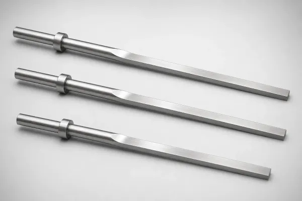
Pair that sheet with the tolerance reality of the tool. DieStrike builds stamping dies to ±0.005 mm on critical dimensions, with component geometry held to ±0.002 mm. Cam drivers and wear interfaces run hardened tool steel at HRC 58 to 62. The shop runs 120+ machines under IATF 16949. Its stamping dies serve connector OEMs including TE Connectivity, Amphenol and Luxshare. On 0.4 mm pitch terminals, side pierce position is measured in tens of micrometres.
Lead times matter for planning. Standard cam units and die components ship in 3 to 7 days. Complete stamping dies ship in 2 to 5 weeks. Ordering standard cam hardware early in the build keeps the cam station off the critical path, and it keeps the wear pairs catalog-replaceable for the life of the die.
FAQ: Cam Unit Selection
Q1. What cam angle should I use for a side pierce in a progressive die?
Start at 45 degrees. It gives a 1:1 travel ratio, so 20 mm of slide travel needs 20 mm of ram travel, and it delivers the full ram force at the slider. Move to 30 degrees only when travel is short and you need 1.732 mm of slide movement per ram mm, which cuts force to 58%. Use 60 degrees only for short-stroke work such as embossing, where the 173% force gain outweighs the loss of travel.
Q2. How much return force does a cam unit need?
Size the return at 15 to 20% of the working force, then check it against slider mass. A 6 kg slider with a 20 mm stroke reversing in 0.2 seconds needs about 1,200 N of initial force. If the calculated spring force falls below that, use a nitrogen gas spring rated 1,000 to 6,000 N. A mechanical return horn also works, because retraction no longer depends on stored energy.
Q3. When can a standard cam unit replace a custom cam block?
When four conditions hold. Required slide travel is within 10% of a catalog size. Working force stays under 50% of the rated load. The cam angle matches a catalog option, and the base pattern fits the die shoe. That covers most side pierce and side form stations at $200 to $1,200 per unit. Go custom above 80 mm of travel or 40 kN of force, or when the slider must be integrated into the die block, at $900 to $3,000 per block.
Q4. How often should cam return springs be replaced?
Replace coil return springs at 250,000 to 500,000 strokes even if they look fine, and inspect free length at every regrind, roughly every 0.05 to 0.1 mm of punch wear. Coil springs lose 10 to 15% of their force by 300,000 cycles, which is enough to leave the slider 2 mm short of home. Nitrogen gas springs last 1,000,000 to 2,000,000 cycles, but verify the 150 bar charge yearly and recharge if pressure drops more than 10%.
Q5. Why do cam units wear out faster than the rest of the die?
Three reasons. Contact pressure on the inclined wear face runs 40 to 100 MPa, far above a normal guide surface. Sliding speed at the driver peaks at bottom dead centre, exactly when load peaks. And lubrication reaches the slider last, so an under-lubricated cam can run 50,000 strokes dry before anyone notices. The fix is a lubrication interval under 10,000 strokes, gib clearance held between 0.02 and 0.05 mm, and wear plate replacement at 0.05 mm of thickness loss.
The Bottom Line
Cam units are decided by five numbers: working force, slide travel, cam angle, return force and gib clearance. Get those right and a cam die runs 1,000,000 strokes at 60 SPM without a crash. Get the return force 15% low and the die is scrap in 3 seconds. Send DieStrike your strip layout and cam requirements for a DFM review with cam sizing, angle ratios and return force confirmed in 24 hours through our contact page.
KEEP READING
Related Reading
Nitrogen Gas Springs vs Coil Springs for Stamping Dies: How to Choose
Force curves, life cycles and cost per 100,000 strokes for both return systems.
Read articleArticleHow to Design Side Actions: Slides, Angle Pins and Locking
The injection-mold counterpart to cam units: slide travel, angle pins and locking.
Read articleArticleHow to Select Perforators for Stamping Dies
Perforator sizing, shoulder types and stripping force for side pierce stations.
Read articleServiceStamping Die Manufacturing
Progressive, transfer and compound dies built to IATF 16949 with 2 to 5 week lead times.
Read articleNEXT STEP
Ready to Start Your Mold?
Send us your element dimensions or part numbers — our team responds within 24 hours with pricing and lead time.

Written by
Ray ChanMold Buyer's Guide Author · Precision Mold Manufacturing Specialist. Ray helps global importers, distributors and OEMs source factory-direct molds and mold parts.