
How to Design Side Actions: Slides, Angle Pins and Locking
Table of Contents
At shot 91,000 of a 12-cavity connector program, the slide on cavity 4 stopped pulling its undercut. A 0.05 mm burr had grown on the heel face. The locking wedge was ground at 18 degrees, the same angle as the angle pin. It should have been 2-3 degrees steeper, so it edge-loaded on every cycle instead of seating flat. The mold spent 11 hours on the bench, and the program wrote off 14,000 parts to the schedule slip.
A side action is the moving steel that releases an undercut pointing sideways. It slides a cavity face or core out of the part's path before ejection, then returns for the next shot. Every slide carries four jobs: form the feature, lock against injection pressure, retract cleanly, and return on time. On a typical mold a single slide adds $3,000-$15,000 of cost and 1-2 weeks of lead time before it ever cycles.
Most undercuts below roughly 0.5-1.0 mm can be solved by draft instead of steel. A 0.5 degree draft change is free in the CAD model, and a slide is not. Real side-action triggers are visible or functional faces that cannot carry draft. Deep holes or threads at 90 degrees to the opening axis are another trigger. Bosses or ribs that would lock behind the cavity steel are the third.
This guide covers the slide mechanism itself, from travel to angle pin to heel steel to maintenance. Part-level undercut strategy belongs in our undercut design guide for automotive parts. Parting line placement sits in our parting line article. Threaded features release through unscrewing, collapsible cores or stripping, which the thread molding guide covers separately.
The Snapshot
- A side action adds $3,000-$15,000 and 1-2 weeks to a mold program (typical industry figures).
- Slide travel equals undercut depth plus 2-3 mm of clearance, never the bare depth.
- Angle pins run 15-25 degrees, and heel wedges lock 2-3 degrees steeper than the pin.
- Cavity pressure of 30-80 MPa pushes the slide face, and the heel absorbs it at 45-52 HRC minimum.
- Service slides every 50,000-100,000 shots and scrap gibs once wear reaches 0.02-0.05 mm.
When a Slide Is the Only Way Out
The trigger question is simple: can the part leave the steel straight up? Walk the release path in the CAD model and check every face against the opening direction. Any feature that blocks that path and cannot be drafted out is a candidate for a side action. A 1.0 mm ledge on a visible A-surface beats any ejection math, because draft cannot fix a negative wall and the steel must move.
The common shop rule sets the threshold at 0.5-1.0 mm of negative geometry. Undercuts below that range can often be drafted out, blended into a radius, or accepted as a parting line step. Undercuts above it need a mechanism unless the mating design tolerates the feature being filled or split. The cost decision happens here, before steel is ordered, not at the T1 trial.
Functional surfaces change the math even when the depth is small. Sealing faces, O-ring grooves, snap-fit beams and textured panels reject draft by function, because a 0.5-1.0 degree wall change alters the seal or the feel. Deep holes and threads at 90 degrees to the opening axis are the clearest case. A 6-8 mm deep side hole needs a side core of similar diameter, and no draft removes a full-circle thread.
Do not start with the mechanism. Start with the part geometry, and let the release route fall out of the undercut position and the ejection side. A feature below the parting plane usually needs a mechanism on the core side. One above it belongs to the cavity side. The classification detail lives in the two guides linked at the top of this article.
Slide vs Lifter vs Collapsible Core
External undercuts usually get slides, and internal undercuts usually get lifters or collapsible cores. The reason is the ejection side. An external feature locks onto the cavity steel, so the mechanism that frees it lives in the moving half pocket beside the cavity. An internal hook or rib locks onto the core, so the mechanism has to rise with the ejector stack to peel the part off.
A lifter rises with the ejector plate at a typical angle of 5-12 degrees and lifts the part off an internal hook, rib or recess. Its lateral travel is limited by the ejector stroke, with 2-10 mm typical for connector and housing work. A collapsible core serves full-circle internal grooves and threads, with segments that cave inward during ejection so the part can lift straight off.
Thread release is a subject of its own, because unscrewing cores and collapsible segments carry their own cycle and cost rules. This guide stays with the external slide and its mechanism. Use the choice matrix below to sort the first decision, then read the section that matches your feature.
| Decision | Slide | Lifter | Collapsible Core |
|---|---|---|---|
| Typical job | External wall undercuts, side holes, ribs at 90 degrees to opening | Internal hooks, ribs and recesses above the ejector plane | Internal threads and annular grooves, about 5-32 mm diameter |
| Feature location | Outside of the part, cavity side | Inside the part, above the core | Inside a bore, full circle |
| Drive | Angle pin, hydraulic or cam on the opening stroke | Ejector stroke through an angled pin | Ejector stroke collapsing the segments |
| Motion | Travel = undercut depth + 2-3 mm | Rise of 5-12 degrees, 2-10 mm lateral travel typical | Segments cave inward by the thread depth |
| Cost per action, typical | $3,000-$15,000 | $3,000-$15,000 band | $8,000-$25,000 per station |
| Service signal | Inspect every 50,000-100,000 shots | Same interval, watch the angled pin | Segment life of 200,000-500,000 shots typical |
← swipe to scroll →
Table note: Cost figures are typical industry ranges for tooling programs. Collapsible core and thread-side data cross-reference our thread molding guide.
Two rules sort the matrix fast. If the undercut faces outward and sits on the cavity side, plan a slide. If it faces inward above the ejector plane, plan a lifter. If it is a full-circle thread or groove in a bore, plan a collapsible core or unscrewing route. The cost band for the first two overlaps, so pick by geometry and ejection access, not by price alone.
How a Side Action Works: Travel and Timing
The classic layout puts the slide in a machined pocket on the moving half. An angle pin fixed in the top plate passes through a bushing in the slide at a set angle. As the mold opens, the pin drives the slide backward and clears the undercut. A heel block on the fixed half wedges the slide during injection. Typical slide strokes run 2-15 mm in connector and automotive work.
Set slide travel at the undercut depth plus 2-3 mm. For a 3.0 mm undercut, that means 5-6 mm of travel. The extra clearance keeps the molded surface clear even as gibs wear and the steel grows with heat. Never set travel equal to the bare depth. Gib wear of 0.02-0.05 mm plus thermal growth eats the margin, and the part drags on the steel.

The mold must open far enough for the pin to pull the full travel. At 20 degrees, a 6 mm slide travel needs about 16-17 mm of mold opening. At 15 degrees the same travel needs about 22 mm. Check this number against the press stroke and the part drop clearance before the design is frozen. A machine swap at T1 is a 1-2 week event.
Timing failures happen on the return stroke, not the pull. If the slide is not home before the mold closes, the pin slams into the bushing face. Typical damage is a peened bushing edge and a 0.05 mm shift of the formed face. A slide position switch or a mechanical return pin on the moving half catches the fault in the first cycle instead of the first thousand.
Angle Pin Design: Angles, Engagement and Wear
The pin angle sets the trade between mold opening length and mechanism wear. The working band is 15-25 degrees. Below 15 degrees, modest travel demands a long opening stroke and a long pin. Above 25-30 degrees, side thrust and wear climb fast because the pin pushes the slide with more force per millimeter of opening.
| Pin Angle | Slide Pull per 10 mm of Opening | Opening Needed for 6 mm Travel | Wear and Thrust | Typical Use |
|---|---|---|---|---|
| 15 degrees | 2.7 mm | 22.4 mm | Lowest pin wear and thrust | Cosmetic faces, long-stroke presses, gentle release |
| 20 degrees | 3.6 mm | 16.5 mm | Balanced wear and stroke | Default for most connector and housing slides |
| 25 degrees | 4.7 mm | 12.9 mm | Rising thrust and bushing wear | Deep undercuts on stroke-limited presses |
| 30 degrees | 5.8 mm | 10.4 mm | High side load, short life typical | Avoid unless opening stroke is hard-capped |
← swipe to scroll →
Table note: Geometry values are derived from tan(angle). Wear statements are typical industry experience, not a catalog rating.
Read the table as a budget. Moving from 15 to 25 degrees cuts the needed opening from 22.4 mm to 12.9 mm, saving machine stroke and base height. The trade is a force rise of roughly 70% through the pin bushing. Pull per millimeter of opening grows from 0.27 to 0.47 of the stroke. Spend the opening if you have it, and hold the angle at 20 degrees or below on cosmetic parts.
Keep the pin engaged for the whole stroke plus margin. The bushing engagement should equal the slide travel divided by tan(angle), plus 10-15 mm. For 6 mm of travel at 20 degrees, that is 16.5 mm plus margin, or roughly 27-32 mm of working engagement. A short engagement lets the pin tip load the bushing edge and score it within 10,000-20,000 shots.

Fit the pin free, because it never locks the slide during injection. A hardened bushing in the slide, nitrided or through-hardened above HRC 55 typical, protects the pocket and is replaceable when it wears. Pin stock runs hardened or nitrided on the working length. Pin diameter follows travel and load, with Ø12-25 mm typical for connector and mid-size molds. Put the pin spec on the drawing so the toolroom does not substitute soft stock.
The Heel: Where Side Thrust Is Actually Stopped
During injection the melt pushes the slide face like a piston. Side thrust equals the cavity pressure times the projected area of the undercut face, with typical cavity pressure of 30-80 MPa. A face 40 mm wide and 8 mm tall at 60 MPa pushes about 19 kN sideways. That load repeats every cycle, and something in the mold must carry it without moving.
The heel block absorbs that force, and the angle pin must not. At full close the pin floats free in its bushing, because the heel seats first and takes the load. If the pin carries injection load instead, it bends, and a bent pin ruins travel timing and wears its bushing oval. Design the wedge so the pin is unloaded the instant the mold is closed.
Grind the heel 2-3 degrees steeper than the pin angle. With a 22-23 degree heel on a 20 degree pin, the wedge face releases contact before the pin starts pulling during opening. That sequence stops edge loading and galling on both faces. A heel ground at or below the pin angle binds on every cycle, which is exactly the failure that opened this guide.

Specify the heel steel like a lock, because it is one. Steel-on-steel heels run 45-52 HRC minimum, often nitrided or fitted with replaceable wear plates. Hardness, taper and contact rules follow the same practice as parting-line side locks, from the 90% blue-contact target to the shim adjustment for wear. Review the selection logic in our side lock selection guide before you order standard or custom wedges.
Check the bearing pressure so the wedge stays stiff. For the 19 kN example on a heel face of 40 by 15 mm, contact pressure lands near 32 N/mm². That sits far under the 200-300 N/mm² typical limit for hardened steel. The wedge then fails by wear or by edge loading, not by crushing. That is why the 2-3 degree angle difference and the 90% contact target matter more than raw size.
Sizing the Slide and Its Steel
Size the slide body so the formed insert is fully supported and the gibs have working length. A common rule sizes the body 10-20 mm wider than the formed feature. Body length along the travel axis runs at least 1.5 times the width. The pocket is cut to match, and the gibs guide the body over the full travel plus a seating margin of 10-15 mm.
Footprint math drives the mold base. Each slide claims 30-60 mm of extra mold footprint in its direction, because the body, gibs and return hardware need room behind the cavity. Two opposed slides add 60-120 mm to the base width, and the base size then sets plate cost and press fit. Confirm the extra width against the press tie-bar spacing before the base is ordered.

Slide bodies use prehardened 718H or P20 at 28-36 HRC, machined and ground without a heat treatment step. Forming faces run as hardened inserts at HRC 58-62, doweled and screwed into the body. Inserts let the shop swap the worn face instead of rebuilding the slide. DieStrike holds cavity insert hardness to HRC 62 within its precision mold program.
Gibs and wear plates carry the sliding load. Graphite-bronze plates resist galling and run well on hardened faces, while hardened tool steel plates carry higher pressure. Gibs start at a sliding clearance near 0.02 mm per side and are condemned when accumulated wear reaches 0.02-0.05 mm. Keepers hold the slide down against lift during retraction. A slide that jumps its pocket on the return stroke is a keeper problem, not a gib problem.
Slide hardware is standard catalog work, from angle pins and bushings to lifters and wear plates. DieStrike manufactures undercut and slide components, from angle pins to wear plates. Mold components hold ±0.002 mm geometry, and assembled molds reach ±0.005 mm accuracy. Order the mechanism from the same source as the mold so the fit, steel and service book stay consistent.
Cooling, Ejection and Slide Size Cost
Slides form real surface area, so they need cooling, but they move. Water lines inside a slide are limited by the travel and by hose routing that flexes every cycle. Typical lines run 6-8 mm diameter with O-ring or hose connections at the slide heel. An uncooled slide face runs hot, and a 10 °C rise on the forming face can add 2-5 s to the cycle on thick-wall parts.
Where a line cannot reach, beryllium-copper cores pull heat at roughly 3-5 times the conductivity of tool steel. Typical BeCu cores cover bosses, ribs and corners inside the slide footprint. They cost more than steel cores but hold the cavity face near process temperature, which protects both cycle time and dimensional stability.
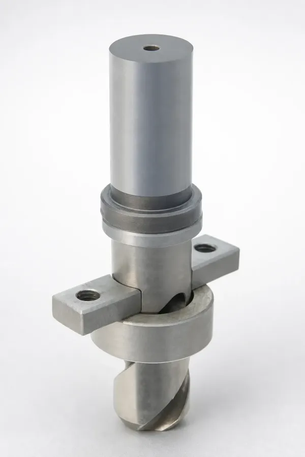
Ejection and slides interact when the part grips the slide. A side core forming a deep hole can stick on the slide face, and then the part rides the slide instead of the ejectors. Typical fixes are 0.5-1.0 degrees of draft on the slide face, polishing the slide steel, or shifting retention to the core side with ejector pins. Ejection mounted on the slide itself is rare, because moving hoses and actuators with the slide raises cost and failure points.
The budget reality is blunt. Each side action adds $3,000-$15,000 and 1-2 weeks to the program. It also adds roughly 1-3 s to the cycle, since the mold opens and closes around moving steel. Multiply by the slide count before approving the design. Four slides on one tool move the quote from the base price toward the top of the band.
Confirm the press before the design is frozen. The press needs stroke for the pin pull and tie-bar clearance for the wider base. Knockout travel matters if the slide or lifter rides the ejector plate. A slide plan that fits the intended machine saves a 2-5 week requote cycle later.
Slide Maintenance and Wear Limits
A slide is a wear machine inside the mold. Plan service every 50,000-100,000 shots, matching the tool's production calendar, and put glass-filled resins at the short end of the band. Log every service event so wear trends are visible before a failure stops the line. An unlogged slide is a surprise with a schedule attached.
Four checks cover most failures: gib clearance, angle pin bushing bore, heel face contact, and slide face condition. Measure gib wear with a feeler gauge or indicator and scrap the gib at 0.02-0.05 mm of accumulated wear. Ream or replace a bushing whose bore has opened past its sliding fit. Re-blue the heel when contact drops below 90% and look for edge loading before it scores the body.
Lubricate at every service with molybdenum-disulfide or graphite grease on the gibs, bushing and heel. A dry slide on glass-filled nylon can gall inside 10,000 shots, long before the 50,000-shot interval arrives. The grease film is cheap, and the scored slide body it prevents is not.
Catching wear at the 0.02-0.05 mm limit costs a gib replacement and a short service stop. Missing it costs a new slide body, a reworked pocket, and 2-3 weeks of program time. Schedule the checks, write down the numbers, and treat the 50,000-100,000 shot interval as a budget line, not a suggestion.
Design Checklist Before the RFQ
Send the slide plan to the mold maker as numbers, not sketches. Eight items make a complete slide data sheet for the RFQ, and each one changes the quote:
- Undercut depth measured perpendicular to the opening axis, with travel set at depth plus 2-3 mm.
- Mechanism family confirmed: external wall feature, so a slide, with lifter or collapsible core ruled out for internal geometry.
- Pin angle of 15-25 degrees, with the needed mold opening stated, for example 16-17 mm at 20 degrees for 6 mm of travel.
- Heel angle 2-3 degrees steeper than the pin, specified at 45-52 HRC minimum or nitrided.
- Side thrust estimate from the undercut face area times the 30-80 MPa cavity pressure band.
- Slide body steel at 28-36 HRC prehardened, with hardened inserts at HRC 58-62 on the forming face.
- Gib clearance and wear limit on the service sheet, starting near 0.02 mm per side with a 0.02-0.05 mm scrap line.
- Cooling demand and service access confirmed with the mold maker before the base order.
DieStrike reviews exactly these eight points in its mold design and DFM review, and returns DFM feedback within 24 hours. The review checks travel against press stroke, heel steel against the thrust estimate, and the base size against tie-bar clearance. That is the point where a $15,000 mechanism decision still costs nothing to change.
FAQ
Q1. When is a side action truly needed instead of draft?
A side action is needed when negative geometry below roughly 0.5-1.0 mm cannot be recovered by draft. Visible or functional surfaces that reject a wall angle also qualify. Deep holes and threads at 90 degrees to the opening axis always need a mechanism, since no draft removes a sideways feature.
Q2. Slide or lifter for my undercut?
External undercuts on the cavity side take a slide. Internal hooks, ribs and recesses above the ejector plane take a lifter rising at 5-12 degrees. Full-circle threads and grooves in a bore take a collapsible core or unscrewing route, with typical costs of $8,000-$25,000 per station for the collapsible option.
Q3. Why must the heel angle be steeper than the pin angle?
A heel ground 2-3 degrees steeper than the pin releases contact before the pin pulls. A heel at or below the pin angle binds and edge-loads every cycle. That scores the wedge face and can stop the slide, as the failure at the start of this guide showed.
Q4. What does a side action add to cost and lead time?
A typical side action adds $3,000-$15,000 and 1-2 weeks to the mold program. It also adds 30-60 mm of mold footprint per slide and roughly 1-3 s of cycle time. Two opposed slides add 60-120 mm to the base width, which raises plate cost and can force a larger press.
Q5. How often should slides be serviced?
Every 50,000-100,000 shots, with glass-filled resins at the short end. Check gibs and scrap them at 0.02-0.05 mm of wear. Inspect the angle pin bushing bore and re-blue the heel below 90% contact. Lubricate at every stop.
The Bottom Line
A slide fails when travel, angle or heel steel is guessed instead of specified. Travel equals depth plus 2-3 mm, pins run 15-25 degrees, heels sit 2-3 degrees steeper at 45-52 HRC. DieStrike builds IATF 16949 precision molds with 120+ machines, holding mold accuracy of ±0.005 mm and returning DFM feedback within 24 hours.
Bring the slide plan into the DFM conversation before steel is cut: contact us with the part file and the eight-point checklist.
KEEP READING
Related Reading
How to Design Parting Lines: Placement and Shut-Off Rules
Parting line placement decides where a slide can sit: flash shows above 0.02 mm, shut-off preloads run 0.01-0.03 mm, and vents open 0.01-0.05 mm.
Read articleArticleHow to Specify Heat Treatment for Mold Steel
Heel and insert hardness belongs on the drawing: prehardened P20 at 28-32 HRC, H13 hardened to 48-52 HRC, with distortion allowed near 0.05-0.15%.
Read articleArticleHow to Maintain a Mold: Weekly/Monthly/Annual Schedule
Slide service fits the mold calendar: lube and gib checks every 50,000-100,000 shots, with wear logged per tool before it reaches the 0.02-0.05 mm limit.
Read articleServiceMold Design and DFM
DieStrike returns DFM feedback within 24 hours, reviewing slide travel, angle pin geometry and heel steel before the mold base is ordered.
Read articleNEXT STEP
Ready to Start Your Mold?
Send us your element dimensions or part numbers — our team responds within 24 hours with pricing and lead time.

Written by
Ray ChanMold Buyer's Guide Author · Precision Mold Manufacturing Specialist. Ray helps global importers, distributors and OEMs source factory-direct molds and mold parts.