
How to Select Side Locks for Precision Injection Molds
Table of Contents
A side lock that lets go does not announce itself. It shows up as a 0.02 mm insert shift on cavity three. It shows up as a flash line that appears on shot 4,000. It shows up as scoring that scrapes the lock face and turns a 200,000-shot tool into a 40,000-shot problem. The mold still cycles, and the parts just stop being in tolerance, one cavity at a time.
Side locks , also called taper locks, interlocks or wedge locks , are the parts that stop that from happening. They keep the two mold halves registered under injection pressure. They hold inserts and cores from shifting sideways when the cavity fills unevenly. On precision tools for connector, sensor and medical work, they are not optional. This guide covers the lock types, the angles, the steel, the sizing rules and the maintenance schedule, with numbers you can put on an RFQ.
DieStrike builds precision injection molds under IATF 16949 and ISO 9001, with 120+ machines in one factory. Our standard tolerance is ±0.005 mm; precision work holds ±0.002 mm. We build for customers like TE Connectivity, Amphenol, Luxshare and Dongshan Precision. Every one of those tools carries side locks sized and ground to a plan. This is how we select them.
The Snapshot
- Engineering plastics generate 400-800 bar cavity pressure (typical published range). At 600 bar, a 100 cm² projected area pushes 600 kN , about 61 metric tons , against the parting line.
- Taper locks at 3-5° convert vertical clamp force into lateral preload. A 3° wedge gives roughly 19:1 mechanical advantage; 5° gives about 11:1 (typical published geometry).
- Lock faces are hardened to HRC 58-62 (typical). DieStrike specs HRC 62 on taper lock faces with case-hardened or nitrided tool steel.
- Typical shop sizing rule: one taper lock per 50-150 cm² of projected area, near the corners, with lock width at 10-15% of the parting-line length it guards.
- Inspect lock faces every 50,000-100,000 shots (typical interval). Re-grind or replace before the mating faces drop below 90% contact.
What Side Locks Do in a Precision Mold
A mold closes on guide pins. Guide pins locate the plates to within their fit clearance, typically 0.01-0.02 mm per side on a precision base. That clearance is fine for closing the mold. It is not fine for holding a parting line shut while 600 bar of melt pushes sideways into an insert seam.
Side locks take over from the guide pins at the parting line. They are precision-ground steel blocks that register the two halves against each other exactly where the cavity is. A taper lock wedges its male half into a matching female pocket. It pulls the insert faces tight and removes the play the guide pins leave.
The failure they prevent is insert shift. When one cavity fills before its neighbor, the pressure difference shoves the cavity insert sideways. A 0.01 mm shift on a 0.5 mm connector wall changes the wall by 2%. Flash appears at the parting line where the steel no longer meets, and every part in that cavity carries the defect.
The other job is protecting the parting line itself. Cavity pressure acts on the projected area of the part and tries to open the mold. If the clamp force holds but the plates flex in the middle, the parting line opens a few microns and flash forms. Side locks add stiffness at the point of load, so the parting line stays closed where it matters.
On multi-cavity tools the case is stronger. Eight or sixteen cavities mean eight parting-line zones under different fill pressures. Locks at each zone boundary hold every cavity to the same reference, instead of letting each cavity fight the clamp on its own.
How Injection Pressure Tries to Separate the Mold
Every mold is a pressure vessel held shut by clamping force. The physics is simple: cavity pressure times projected area equals the force trying to open the mold. The clamp must exceed that force, or the parting line breathes.
Typical cavity pressure for engineering plastics runs 400-800 bar (published range). Polycarbonate and glass-filled nylon sit at the top of that band; unfilled polypropylene sits near the bottom. At 600 bar , 60 MPa , a single cavity with 100 cm² of projected area generates 600,000 N. That is about 61 metric tons against the parting line.
The clamping force answers with the mold tonnage. A 200-ton press applies roughly 1,960 kN. That sounds like a wide margin, until you spread it across the plate area and subtract the beam deflection in the middle. A 500 mm span of plate under 600 kN of cavity load can deflect several microns at the center. That is exactly where flash shows up.
Now add the sideways component. The melt enters the cavity and flows outward from the gate. Pressure on one side of an insert is rarely identical to the pressure on the other side during filling. The imbalance shoves the insert laterally, and the parting line opens on the low-pressure side.
Side locks carry that imbalance. A taper lock preloads the insert laterally when the mold closes. The first 0.005 mm of pressure-driven shift then works against the wedge, not against free play. That is the difference between a tool that holds ±0.002 mm and one that drifts with every fill variation.
Flat Side Locks vs Taper Locks
Side locks divide into two families by geometry: flat locks and taper locks. Flat locks are rectangular blocks with parallel faces. Taper locks carry an angle on their mating faces and wedge shut. The choice changes how the lock carries load.
Flat or Straight Side Locks
A flat lock has two parallel, precision-ground faces that slide together vertically. It controls lateral position in two directions but carries almost no vertical load, because the faces are perpendicular to the parting line.
Flat locks are simple to make and easy to measure. Two ground faces, a dowel-pinned pocket, and a shim for adjustment cover most needs. They suit low-pressure tools, secondary alignment duties, and inserts that must hold a fixed center distance without being wedged.
Their weakness is clearance. Parallel faces need sliding clearance, typically 0.005-0.015 mm (typical published fit), and that clearance is exactly the shift the lock is supposed to prevent. Under asymmetric pressure, a flat lock limits movement to its clearance rather than eliminating it.

Taper or Angled Locks
A taper lock mates two angled faces, typically 3-10° per side. When the mold closes, the wedge drives the faces together under the clamp force. The result is a preload that removes clearance entirely and pulls the insert or plate into a repeatable position every cycle.
The mechanical advantage is real. A 3° taper converts roughly 19:1 of vertical force into lateral force. Published geometry: tan 3° ≈ 0.052, so lateral force ≈ clamp force × 0.052 against sliding. At 5° the ratio drops to about 11:1. Shallower angles lock harder but release more slowly; steeper angles release cleanly but carry less lateral preload.
Taper locks are the default for precision work because they register to zero play. The trade is cost: the faces must be ground as a matched pair, verified optically or on a CMM, and protected from wear with hardened steel or wear plates.
External vs Internal Side Locks
Beyond geometry, side locks split by location: external locks mounted on the outside of the mold, and internal locks hidden inside the mold structure. Location drives access, cost and how much steel the lock can use.
External Side Locks
External locks bolt to the outside faces of the A and B plates, at the parting line. They are visible, accessible, and easy to adjust or replace without pulling the mold apart. Typical external taper locks run 60-200 mm long (typical commercial sizes).
External locks suit large molds with thick plates and high projected area. They add stiffness at the plate edge, which is useful when the clamp force concentrates there. They also give maintenance crews a service point they can reach with the mold still in the press.
The cost is footprint. External locks widen the mold envelope, and on molds running in tight machine clearances that can be a constraint. They also leave the center of large plates unsupported, so very wide molds often combine external locks with internal ones.
Internal Side Locks
Internal locks sit inside the mold, either between plates or beside the cavity block. They protect the parting line at the load point, not at the plate edge. Internal taper locks are common on insert-based and slide-based tools where exterior space is limited.
Internal locks are the right choice when the load is local , a deep cavity, an insert seam, or a slide that needs lateral support. They are also standard on molds with undercut and slide systems, where the slide guides and the lock share the same pocket.
The trade is serviceability. An internal lock must come out with the insert or the plate, and wear checks mean breaking down the mold. That makes maintenance scheduling and documentation more important, which is why DieStrike records lock inspection on the tool's service sheet.
Choosing the Locking Angle: 3°, 5° or 10°
The taper angle is the most consequential number on a side lock. It trades lateral preload against release reliability. The three common values are 3°, 5° and 10° per side (typical mold industry practice), and each has a distinct job.
3° locks deliver the strongest wedging. They are the choice for precision inserts that must not move under 400-800 bar pressure. The cost is release: a 3° wedge can stick if lubrication fails, and opening force spikes. Use 3° where rigidity beats service convenience.
5° is the general-purpose default. It holds a solid preload, releases reliably, and tolerates minor contamination on the faces. Most precision production molds at DieStrike run 5° taper locks, with 3° reserved for the tightest insert-registration jobs.
10° locks release almost by gravity. They are common on hot-runner and large-plate tools where the priority is clean opening and where lateral loads are modest. The wedging effect at 10° is roughly one-third of the effect at 3°. Compare tan 10° ≈ 0.176 with tan 3° ≈ 0.052. The parting line then relies more on clamp force.
Match the angle to the load, not to habit. A 10° lock on a glass-filled nylon tool is a flash waiting for a fill imbalance. A 3° lock on a low-pressure cosmetic part is over-engineering that complicates the opening stroke.
Material, Hardness and Wear Plates
A side lock lives on sliding contact under load. The faces rub every cycle, at every close, with clamp force behind them. Steel choice and hardness decide whether the faces wear evenly for 500,000 shots or gall on shot 5,000.
Tool Steel and Lock Face Hardness
Tool steel is the standard. Pre-hardened grades around HRC 28-32 work for low-volume tools, but production molds need harder faces. The typical specification for lock faces is HRC 58-62 (published mold practice). DieStrike specs HRC 62 on taper lock faces.
Hardness comes from case hardening or nitriding. Case hardening (carburizing) gives a deep, tough case, typically 0.8-1.2 mm deep on tool steel (typical). Nitriding gives a thinner, very hard surface layer, typically 0.2-0.5 mm, with minimal distortion. That matters on a ground taper that must keep its angle.
Nitriding is the better fit for taper locks because the part is ground after heat treatment. The nitride layer sits on the finished geometry, so the taper stays true. Case-hardened locks are usually case-hardened, then ground, which is why the case depth must exceed the grinding allowance.
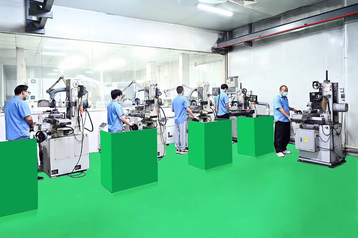
Match the two mating faces in hardness. A soft male lock wearing against a hard female pocket transfers the wear to the part you can easily replace, which is the intended design. Mixing two hard, dry faces without lubrication invites galling at the contact point.
Wear Plates and Gibs
Wear plates and gibs are the replaceable interfaces that take the wear so the lock body does not. A wear plate is a thin hardened strip, typically 3-10 mm thick, bolted to one side of the lock pocket. A gib is a guided strip that also adjusts clearance.
The principle is sacrificial surface. The lock body stays registered and doweled; the wear plate takes the sliding load and gets swapped when it wears. Standard wear plate materials are hardened tool steel or bronze-backed composites, run against the hardened lock face.
Gibs add adjustment. A gib with shims or taper adjustment lets the maintenance crew reset clearance without re-machining. On slide tools, gibs guide the slide and the side lock in the same pocket, so the two are specified as a matched set.
Budget for wear plates wherever the lock will be serviced more than once. The plate costs a fraction of re-grinding the lock body, and it turns a 2-day rework into a 2-hour service stop.
Sizing Rules: How Many Locks and How Big
Sizing starts with the separation force, then divides it across locks positioned where the load lives. The target is contact pressure on the lock faces that stays safely below the steel's bearing limit, with margin for fill imbalance.
A typical shop rule of thumb is one taper lock per 50-150 cm² of projected area, placed near the corners or at load concentration points. A 400 cm² multi-cavity tool gets four corner locks, not one big center lock, because corners resist the plate bending that produces flash.
Lock width follows the parting line. A common starting point is lock width at 10-15% of the parting-line length the lock guards (typical practice). A 200 mm cavity edge gets a 20-30 mm lock; a 500 mm edge gets 50-75 mm of total lock width, split across two locks.
Check the contact pressure. At 600 bar on a 100 cm² cavity, the 600 kN separation load spreads across the lock faces. Four locks at 40 mm × 40 mm of engaged face each give 6,400 mm² of contact. That is about 94 N/mm², under the 200+ N/mm² bearing limit of hardened tool steel. The margin absorbs fill imbalance.
| Lock Type | Locking Angle | Application | Typical Size Range |
|---|---|---|---|
| Flat / straight side lock | 0° (parallel faces) | Low-pressure tools, secondary alignment, fixed center distances | 25-50 mm long × 10-25 mm wide |
| Taper lock, 3° | 3° per side | Precision insert registration, maximum lateral rigidity | 40-100 mm long |
| Taper lock, 5° | 5° per side | General precision production molding | 40-120 mm long |
| Taper lock, 10° | 10° per side | Hot-runner and large-plate tools, clean release priority | 30-80 mm long |
| External wedge lock | 3-10° | Large plates, thick parting lines, high projected area | 60-200 mm long |
| Internal lock with gibs | 3-5° | Insert-based and slide-based tools, limited exterior space | Sized to insert or slide width |
← swipe to scroll →
Never size locks by weight of the mold. The load is the cavity pressure times projected area, not the steel mass. A lightweight 8-cavity connector mold sees the same 400-800 bar as a heavy automotive tool. The locks just get smaller, because the projected area is smaller.
Machining and Alignment: Matched Tapers and Measurement
A taper lock is only as good as the match between its two faces. The male taper and the female pocket must agree in angle to within a few minutes of arc. Their centerlines must align with the mold datums. That is grinding and measurement work, not milling work.
Matched Taper Grinding
Taper faces are finish-ground as a matched pair. The male lock is ground first, then the female pocket is ground against it, or both are ground to a master angle block. Typical practice holds the angle to within ±0.05° and the faces flat within 0.003 mm.
The grinding sequence matters. The lock body is machined, heat-treated, then ground on the datum faces before the taper is cut. Hardening before grinding means the taper geometry survives the heat treatment, and the datum faces stay true to the mold base.
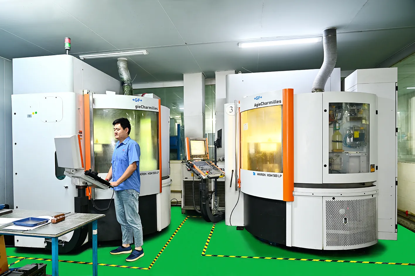
Pockets are located by dowel pins from the mold datums, not by eyeball or by the plate edges. A lock pocket located 0.01 mm off datum shifts the whole lock, and the lock faithfully holds the mold in the wrong position.
Verification
Angle and position get measured, not assumed. A sine bar or optical comparator checks the taper angle; a CMM checks the lock position against the cavity datums; a blue-check on the faces verifies contact percentage.
Contact verification is the final gate. Prussian blue on the male face, close the mold, and the transfer pattern must cover at least 90% of the face. Less contact means the preload concentrates on a ridge, and the ridge wears first.

At DieStrike, lock geometry is verified on the same CMM equipment that checks the cavity inserts, against the same datums. That keeps the lock and the insert on one reference system, which is what makes ±0.002 mm assembly possible.
Maintenance: Lubrication, Wear Checks, Re-Grinding
Side locks wear by design; the maintenance program decides whether the wear is controlled or catastrophic. Three disciplines cover 90% of lock failures: lubrication, inspection on schedule, and re-grinding before the face degrades.
Lubricate the taper faces on every planned maintenance stop. A thin film of molybdenum-disulfide grease on the mating faces cuts friction and prevents galling on the close stroke. Dry faces on a 3° lock are a stick waiting to happen.
Inspect every 50,000-100,000 shots (typical interval), whichever comes first on the service sheet. Look for scoring, edge breakdown, and witness marks that indicate the lock is carrying load where it should not. Check the blue contact pattern; below 90% contact, the preload is uneven.
Re-grind when contact drops or when scoring appears. Grinding removes the damaged surface and restores the angle, but it changes the lock length. Shim the base or replace the lock to restore position; never grind without re-verifying the datum relationship.
Log every service event. Mold service records that track lock wear per 100,000 shots turn maintenance from guesswork into prediction. The tool that gets re-ground at 300,000 shots instead of failing at 340,000 is the tool that stays on schedule.
Standard Parts vs Custom Side Locks
Most side locks do not need to be invented. HASCO, DME and MISUMI all catalog taper lock and interlock systems in standard sizes, with ground faces and published tolerances. Standard parts ship fast and price predictably; custom locks exist for the cases standards cannot cover.
Standard taper locks are the right call for 80% of tools. They come in increments covering 25-200 mm lengths. Angles of 3°, 5° and 10° are typical in the catalogs, and the faces are ground to repeatable tolerances. Buying standard means replacement parts are a catalog number, not a machining project.
When Custom Locks Earn Their Cost
Custom locks earn their cost on three occasions: unusual angles, unusual sizes, and locks that must share geometry with an insert or slide. A lock integrated into the cavity insert, for example, cannot come from a catalog because its datum is the insert itself.
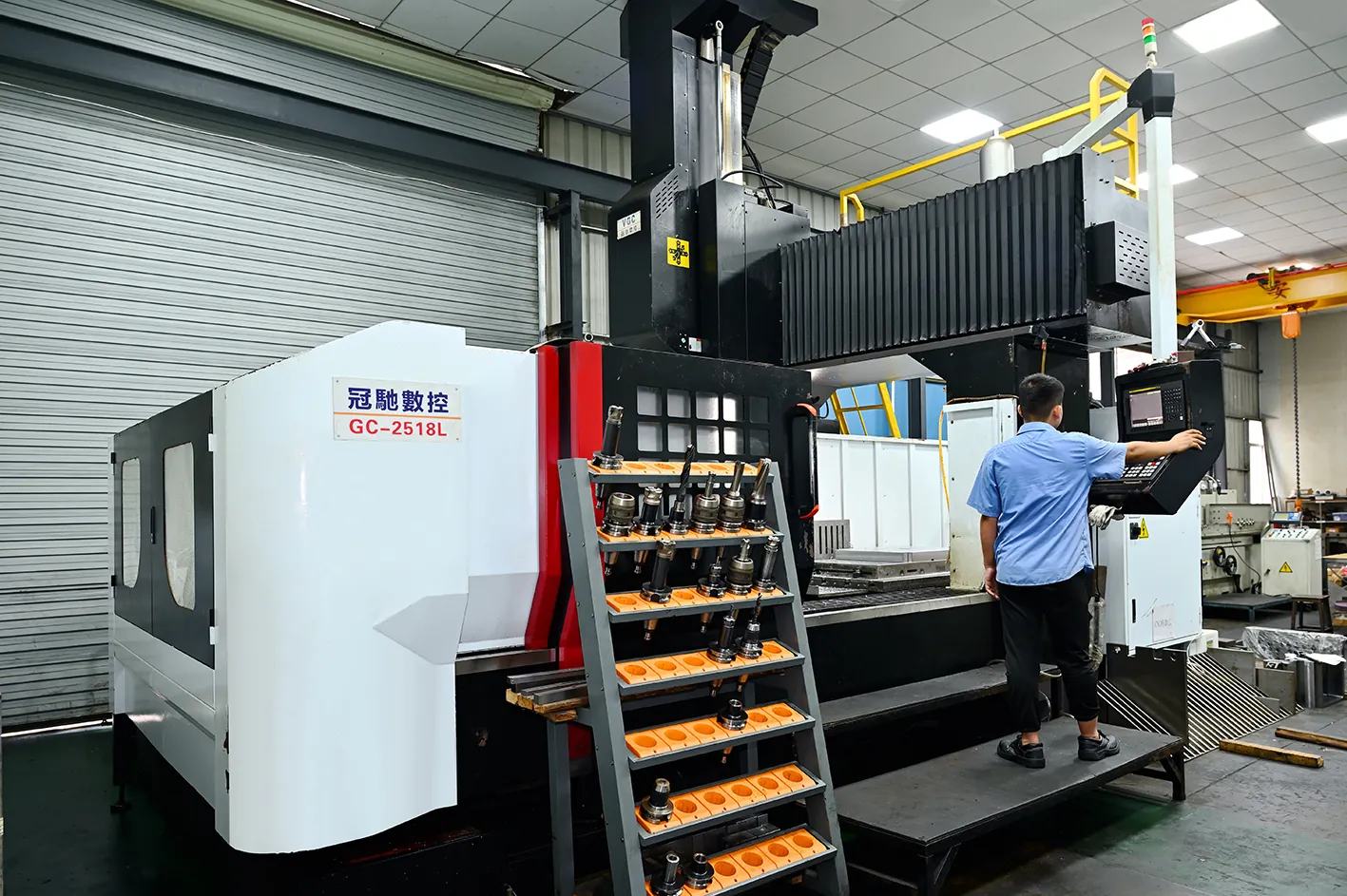
DieStrike carries standard lock systems in stock and machines custom locks in-house. Standard parts lead 3-7 days; custom locks add machining and grinding time but hold the same HRC 62 face spec and the same ±0.003 mm flatness verification. The mold base specification guide covers how locks, pins and base interact on the RFQ.
One rule applies to both paths: put the lock spec on the drawing. Angle, hardness, material, contact target and inspection method belong in the print or the RFQ, the same way the cavity tolerance is. A lock specified as "3° taper, HRC 60 min, 90% blue contact" is a deliverable. A lock specified as "side lock" is a guess.
FAQ
Q1. What is the difference between a side lock and a guide pin? A guide pin locates the plates during closing and carries roughly 0.01-0.02 mm of fit clearance. A side lock registers the parting line zone itself, removes that play with a precision ground wedge, and carries the lateral load from cavity pressure.
Q2. Do I need side locks on every mold? No. Low-pressure, single-cavity tools with modest projected area can run on guide pins alone. Precision tools, multi-cavity tools and any insert-based construction should carry locks, because the fill imbalance and parting-line deflection are real at 400-800 bar.
Q3. What taper angle should I use? 5° is the general-purpose default. Use 3° where insert registration is critical and release can be managed; use 10° on large or hot-runner tools where clean opening matters more than lateral preload. Match the angle to the load.
Q4. How hard should lock faces be? HRC 58-62 is typical, achieved by case hardening or nitriding. DieStrike specs HRC 62. Hardness must match on both faces, and the faces need lubrication to avoid galling.
Q5. How often should I inspect side locks? Every 50,000-100,000 shots is the typical interval, tied to the service sheet. Check the blue contact pattern and look for scoring. Re-grind or replace when contact drops below 90%.
Q6. Standard or custom side locks? Standard HASCO, DME or MISUMI locks cover most tools and ship in 3-7 days at DieStrike. Go custom when the lock must share geometry with an insert or slide, or when the angle or size is not in the catalog.
The Bottom Line
Side locks are cheap relative to the failure they prevent. A 0.02 mm insert shift produces flash, sorting lines and scrap across every shot until someone finds the cause. A ground, hardened, correctly angled lock removes the shift at the source.
Select them by load, not by habit: compute the separation force from the 400-800 bar cavity pressure. Choose 3-5° tapers for precision zones, spec HRC 58-62 faces, and size one lock per 50-150 cm² of projected area. Put the angle and hardness on the drawing.
DieStrike builds precision molds under IATF 16949 and ISO 9001. Standard tolerance is ±0.005 mm; precision work holds ±0.002 mm. Every tool carries locks that are ground, measured and documented. The same discipline that holds cavity geometry to microns is what keeps the locks holding it. Start with the precision tolerance chain to see how lock selection fits the full build.
NEXT STEP
Ready to Start Your Mold?
Send us your element dimensions or part numbers — our team responds within 24 hours with pricing and lead time.

Written by
Ray ChanMold Buyer's Guide Author · Precision Mold Manufacturing Specialist. Ray helps global importers, distributors and OEMs source factory-direct molds and mold parts.