
How to Design Dies for Precision Connector Terminals
Table of Contents
A connector program rejected 40,000 terminals because the burr measured 0.011 mm against a 0.008 mm limit. The die came off the press for six days of punch replacement and regrinding, and the plating line sat idle for two of them. A regrind had opened the punch-to-die clearance to 9 percent per side. This article sets out the die numbers that hold a terminal program in tolerance.
It covers terminal geometry, strip grades from 0.08 mm to 0.40 mm, in-die bending springback, punch clearance and the CTQ checks that release a die.
The Snapshot
- Burr at 5 percent of strip thickness. That is 0.004 mm on 0.08 mm strip and 0.020 mm on 0.40 mm strip. A clearance opened to 9 percent per side crosses the limit within 20,000 strokes.
- Punch-to-die clearance of 3 to 6 percent per side. On 0.15 mm phosphor bronze that is 0.005 to 0.009 mm per side. Die roll lands at 10 to 25 percent of strip thickness.
- Inside bend radius under 0.5 times thickness. A 0.15 mm terminal bends at 0.075 mm inside radius, with 3 to 8 degrees of springback on phosphor bronze.
- Pilot accuracy better than 0.02 mm. Pitch holds within 0.03 mm on a 2.54 mm connector pitch. A contact force spread above 15 percent across a housing usually means the pilots have worn.
How Terminal Geometry Sets the Die Architecture
A connector terminal is a contact spring, a crimp joint and a stamped frame in one part. Pitch runs from 0.4 mm on a board-to-board connector to 2.54 mm on a wire-to-board header. One strip feeds every one of those features through a progression of 2 to 12 mm.
Start from the mating geometry, not from the strip layout. The cantilever contact spring carries the contact force. It needs a free length of 2 to 5 mm and a working deflection of 0.15 to 0.6 mm. The bend radii inside that beam decide how far the force varies from part to part.

The crimp barrel is a rolling form rather than a sharp bend. A 0.20 mm barrel wall in 0.25 mm brass needs an inside radius under half the thickness. The forming station then curls the seam without thinning that wall. Wall thinning above 10 percent turns into a pull-out failure at 35 N instead of the 60 N the wire size requires.
Count the stations before you size the die block. A two-position terminal takes 10 to 16 stations, and a shielded or multi-beam design takes 20 or more. Blanking, two or three bends, a lance and a cut-off are the minimum set. Each extra station adds 40 to 60 mm of die length.
| Terminal feature | Typical dimension | Die station | Tolerance held |
|---|---|---|---|
| Contact spring bend | 0.075 to 0.20 mm inside radius | Progressive bend, two stages | ±0.03 mm on a 2 to 5 mm free length |
| Crimp barrel roll | 0.20 to 0.40 mm barrel wall | Rolling and curling station | Wall thinning under 10 percent |
| Lock lance or window | 0.4 to 1.2 mm wide | Lance and coining station | ±0.02 mm on position |
| Cut-off and progression | 2 to 12 mm feed pitch | Cut-off and carry-out | ±0.02 mm pitch, ±0.10 mm over 10 pitches |
| Contact point window | 1 to 3 mm long plated area | Blanking station | ±0.05 mm, no burr on the mating face |
← swipe to scroll →
Table note: dimensions are typical values for wire-to-board and board-to-board terminals in the 0.4 mm to 2.54 mm pitch range. Confirm each one against the connector drawing and the mating housing before the strip layout is released.
Group the stations by function so that each one carries a single job. Blanking, bending and lancing in the same station loads one punch block from three directions and moves the strip while it is loaded. Terminal dies that hold 0.02 mm pilot accuracy separate those operations.
Strip Material, Temper and Gauge
Connector terminals run on phosphor bronze and brass, with beryllium copper or a copper-nickel-silicon alloy reserved for high-temperature connectors. Phosphor bronze C5210 and C5100 carry the contact springs. Brass C2600 carries the crimp barrels and the shells.
Gauge spans 0.08 mm on a fine-pitch board connector to 0.40 mm on a heavy crimp terminal. Temper decides the tooling as much as the alloy does.
C5210 in spring temper reaches 650 to 750 MPa tensile strength and HV 190 to 230. C2600 in half-hard temper sits at 400 to 480 MPa and forms more easily. Choose the temper from the contact force target, then design the die around the springback that temper produces.
Rolling direction is a die design constraint rather than a purchasing detail. A bend line running across the rolling direction forms at 0.3 times thickness inside radius. Turn that same bend 90 degrees and the minimum radius grows past 0.5 times thickness. Set the strip layout so the principal bends cross the rolling direction at 45 to 90 degrees.
Slit edges carry a burr of 0.01 to 0.03 mm and a work-hardened layer 0.02 to 0.05 mm deep. A terminal that uses the coil edge as a datum will move 0.02 to 0.05 mm between coils. Reference the piercing pilots instead of the coil edge.
Burr, Run-Out and Camber Limits
Burr height on a terminal is capped at 5 percent of strip thickness, and some tier-1 programs hold 3 percent on the mating face. On 0.08 mm strip that is 0.0024 to 0.004 mm. Measure it on a cross-section at 20x to 50x instead of judging it by feel. Clearance, punch sharpness and die entry angle drive burr more than any other variable, as our guide to preventing stamping burr sets out.
Burr forms on the side the punch exits, so the die designer decides where it lands. On a terminal that slides into a housing, burr belongs on the non-mating face. Inside a crimp barrel the burr should face the wire, where it adds grip instead of cutting the wire strands.
Camber is set at slitting and arrives with the coil. Terminal stock is specified at 1 to 3 mm of camber per 1,000 mm of length, and most tier-1 programs hold 1 mm. Check camber at goods-in on every coil. A bowed coil feeds 0.05 mm sideways across a 200 mm progression, and that error adds to the pilot error.
Roller straighteners and strip guides remove camber up to a point. They cannot remove the twist that camber causes, and twist shows up as a tilted contact face after plating. Run each coil through the straightener at the same tension and log the setting.
Punch and Die Clearance for Thin Strip
Clearance is the strongest lever on burr and on punch life. Terminal dies run 3 to 6 percent of strip thickness per side. On 0.15 mm phosphor bronze that is 0.005 to 0.009 mm per side, and on 0.08 mm strip it is 0.002 to 0.005 mm. Below 3 percent the punch burnishes the wall and wears at the corner. Above 6 percent the burr grows and the fracture face tears.
Die roll follows clearance. A punch cutting 0.15 mm phosphor bronze at 5 percent clearance leaves a die roll of 10 to 20 percent of thickness. The burnish band covers 40 to 60 percent of the edge and the burr stays under 0.007 mm.
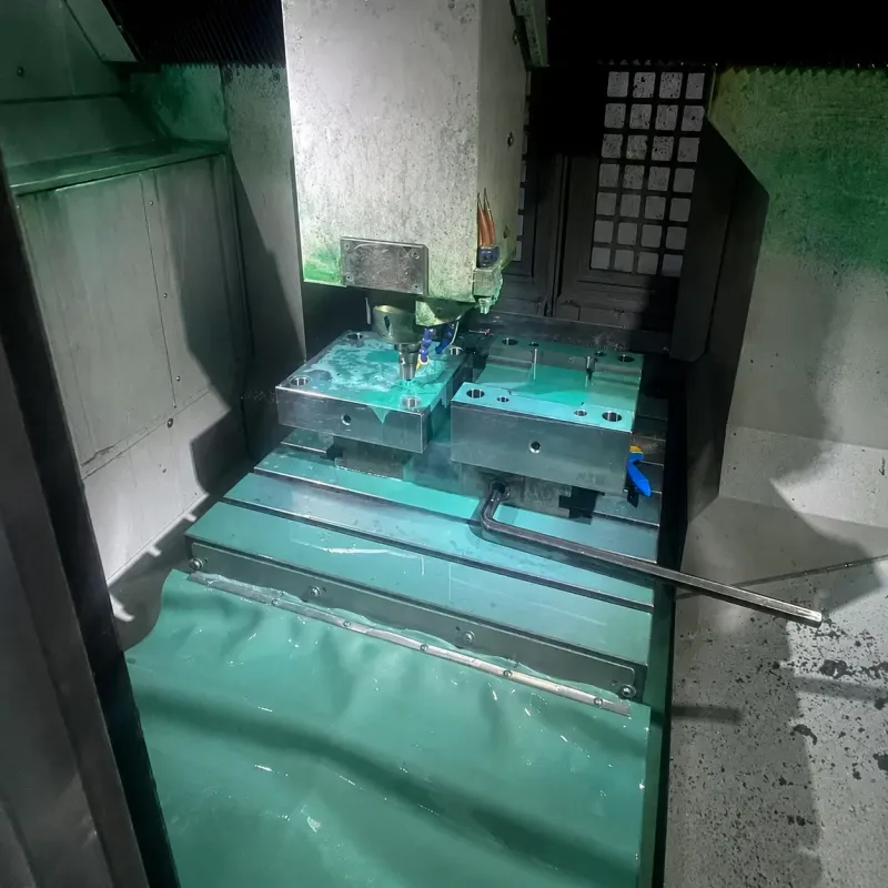
Clearance wanders with every regrind unless the die block is built to hold it. Shim the punch block rather than the die insert, and re-check clearance after each sharpening. A die that starts at 5 percent and reaches 9 percent after three regrinds produces a 0.011 mm burr. That part fails any connector specification.
| Strip gauge | Typical alloy and temper | Clearance per side | Burr target |
|---|---|---|---|
| 0.08 mm | C5210 spring temper | 0.002 to 0.005 mm | Under 0.004 mm |
| 0.15 mm | C5210, C5100 | 0.005 to 0.009 mm | Under 0.0075 mm |
| 0.25 mm | C2600 half hard | 0.008 to 0.015 mm | Under 0.0125 mm |
| 0.40 mm | C2600 half hard | 0.012 to 0.024 mm | Under 0.020 mm |
← swipe to scroll →
Table note: clearance is 3 to 6 percent of strip thickness per side, taken at the narrowest point of the die opening. Confirm the alloy temper on the mill certificate and re-measure clearance after every sharpening.
Build adjustment into the insert. Ground shims of 0.005 mm and 0.010 mm under the die insert let a toolmaker move clearance by 0.002 mm without touching the punch. Keep a spare insert set for every high-wear station.
In-Die Bending: Radius, Springback and Cam Stations
Bending decides whether a terminal lands inside its contact force window. Terminal bends run an inside radius under 0.5 times thickness, often 0.075 to 0.20 mm. At that radius the neutral axis shifts toward the inside face, so bend allowance follows a K-factor of 0.33 to 0.45.
Springback is the error the die has to absorb. Phosphor bronze at 650 to 750 MPa springs back 3 to 8 degrees, and brass springs back 2 to 5 degrees. Form the bend to 95 degrees to hold 90 degrees. Coining the bend root to a 0.02 to 0.05 mm flat removes most of the springback that is left.

Strip at 0.10 mm needs a different bending station from strip at 0.30 mm. A conventional die shoulder drags on the outer fibre of thin strip and tears it. A roller bending station forms the radius over a hardened roller of 1.5 to 3 mm diameter, so the strip enters and leaves tangentially.
A bend that runs vertically in a horizontal die needs a cam or a wedge. Cam drivers run 25 to 45 degrees. A 30 degree wedge turns a 20 mm press stroke into roughly 10 to 12 mm of slide travel. Below 20 degrees the slide tends to stick. Above 45 degrees the side load on the wear plates climbs and the slide rocks.
Return springs must close the slide before the press reaches top dead center.
Every bend pulls material from the carrier, so clamp or pilot the strip through the forming stations. Pull-in of 0.05 mm at one bend station becomes 0.15 mm of pitch error three stations later. A die that ignores pull-in cannot hold 0.02 mm pilot accuracy, however well the pilots are made.
Piloting, Feed Accuracy and Strip Tension
Pilot accuracy better than 0.02 mm comes from the pilot, the die button and the strip, not from the press. Pilots enter the strip before the punches touch it. A pilot of 1.5 to 3 mm runs in a hardened button. Button clearance is 0.005 to 0.010 mm with a 0.5 to 1 mm lead radius.
Servo feed accuracy on 0.15 mm phosphor bronze runs ±0.02 to ±0.05 mm per feed, and the error accumulates along the progression. Close the loop with pierced pilots placed 2 to 4 pitches after the feed. The tool then sets pitch position instead of the feeder.
Pull-through is the tension the die pulls against once the feeder releases and the pilots take over. Hold it at 5 to 10 percent of the strip yield strength and measure it with a load cell or a dancer roller. Low tension lets the strip sag and follow its own camber. High tension stretches the strip permanently, and a 0.2 percent stretch across a 12 mm progression is 0.024 mm of lost pitch.
Lubrication belongs in the same budget. A film of 1 to 3 µm keeps friction stable at 600 SPM. A dry strip picks up copper on the punch face within 50,000 strokes, and that pickup transfers to the strip as a smudge after plating.
Punch Steel, Coatings and Sharpening Intervals
Powder metallurgy high-speed steel and fine-grain carbide cover most terminal dies. PM-HSS in the M4 or ASP 23 class holds 200,000 to 500,000 strokes between sharpenings on 0.15 mm phosphor bronze. Fine-grain carbide at 88 to 92 HRA runs 3 to 5 times that interval, and it fails by chipping rather than by wear.
Match the grade to the station. Carbide belongs on the blanking and lance stations where abrasive wear dominates. PM-HSS belongs on the forming and cam stations, where a tough edge beats a hard one. A chipped carbide insert in a cam slide costs a press stop of 2 to 6 hours.
Coatings extend the interval rather than the clearance. TiN at 2 to 4 µm suits general blanking. TiAlN at 3 to 5 µm holds where the punch face runs above 300 °C. DLC at 1 to 3 µm cuts copper pickup on the forming stations. Re-coat when the layer is worn through on more than 20 percent of the punch face.
Sharpening follows stroke count, not the calendar. Remove 0.02 to 0.05 mm per pass on a surface grinder and keep the cutting edge square to the punch axis. Regrind when the burr reaches 60 to 70 percent of the limit rather than at the limit. Track the material removed, and replace the punch after 3 to 5 mm of accumulated removal. Our guide to selecting stamping die steel covers the grade trade-offs in full.
Punch and die insert supply is often the long pole in a rebuild. Our stamping die manufacturing group keeps carbide and PM-HSS insert stock for terminal programs, with standard components shipping in 3 to 7 days.
Slug Pull Detection and In-Die Force Monitoring
A slug pulled back onto the die face destroys a station in one stroke. The slug comes back for three reasons. The die hole holds it, the punch face has worn, or the strip draws it out at 600 strokes per minute. Most slug pull begins with a clearance that has grown past 6 percent.
Prevent it in the geometry. Taper the die entry 0.5 to 1 degree over 2 to 3 mm. Hold the die land at 3 to 5 mm and polish the hole to Ra 0.2 µm. A 0.2 to 0.5 mm vent hole in the punch removes the pressure that holds a slug against the face.

Detect the fault in the load signature. Monitor each station with a strain gauge under the die block or a tonnage monitor on the press. A station carrying a slug shows a blanking peak 8 to 15 percent above baseline. Set the stop window at plus or minus 5 percent of the baseline peak and the press halts before the next stroke damages the punch.
Log every stop against the stroke counter. A station that trips twice inside 200,000 strokes needs a clearance measurement and a die land inspection, not a fresh reset.
Cleanliness Rules Before Plating
A terminal leaves the die clean or it leaves as scrap. Plating rejects come from oil film, copper pickup, fingerprints and burrs that trap electrolyte. The plating line cannot correct any of them.
Keep grease fittings and open oil cups off a terminal die. Use a vanishing lubricant at a film of 0.5 to 1.5 g per square metre and check the film weight rather than the visible sheen. Above 2 g per square metre the residue survives a standard alkaline clean.

Copper pickup shows on the punch face after 30,000 to 80,000 strokes as a smear that transfers to the strip. Polish the smear off or add a DLC coating at 1 to 3 µm. Another option is opening the clearance to the top of the 3 to 6 percent range. Never wipe a punch face with a cloth that carries grease or metal particles.
Handle finished terminals in nitrile gloves. Keep tape and labels off the strip and keep cardboard away from the contact area. Wrap reels in VCI paper when the parts wait more than 3 days, and store them off the floor.
Running 400 to 800 SPM and Coil Change Uptime
Terminal presses run 400 to 800 strokes per minute. At 600 SPM one stroke lasts 100 ms, and the feed, pilot, blank, bend and cut-off sequence fits inside it. Die protection has about 20 ms to see a fault and stop the press.
Tonnage is not the constraint at that speed. A terminal die cutting 0.15 mm phosphor bronze over a 40 mm cut perimeter needs under 15 kN per stroke. Dynamic accuracy is the real limit. The die needs ball-cage guides with 0.005 to 0.010 mm clearance and a ram that repeats inside 0.01 mm.
Guide wear follows stroke count rather than tonnage. At 600 SPM two shifts deliver 2 to 3 million strokes a week. Put guide clearance on a monthly check and the sharpening interval on a stroke counter. A worn guide shows up as burr growth long before it shows up as a dimension.
Coil changes decide the uptime number. Run two reels with a splicer or an accumulator holding a 20 to 40 m loop. A change then costs 0 to 3 minutes instead of 15 to 25 minutes. At 600 SPM a 25 minute stop costs about 15,000 terminals.
A 100 kg coil at 30 mm width and a 12 mm progression holds 5 to 6 hours of strip. Schedule the change at a planned break.
CTQ Inspection and Trial Acceptance
Four characteristics decide whether a terminal die is released: pitch, burr, contact force and pull-out. The rest are secondary.
Measure pitch on a vision system at 20x across 30 parts. A single pitch holds within ±0.03 mm and 10 consecutive pitches hold within ±0.10 mm. Measure burr on a polished cross-section at the fracture side of the blanked edge, not by touch.
Measure contact force with a spring gauge or a load cell at the working deflection of 0.15 to 0.6 mm. A wire-to-board terminal typically targets 1.5 to 4 N. The spread across 10 positions in one housing belongs under 15 percent, and insertion force under 15 N per contact.
Pull-out is the acceptance test for the crimp. A crimped terminal on a 0.5 mm² wire typically holds 60 to 100 N, measured on a tensile tester at 25 mm per minute. Contact force and pull-out both belong in the PPAP file, and tier-1 automotive connector programs require capability data with the sample.
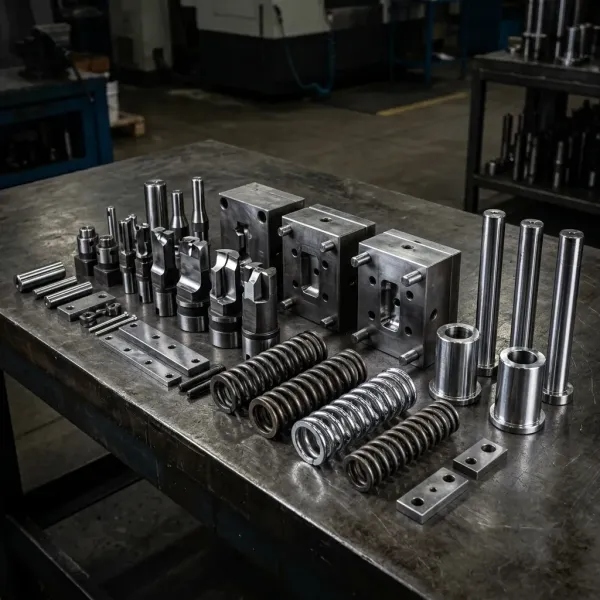
Run the trial in three steps. T0 proves the strip layout and the bends on hand feed. T1 runs 30 to 50 strokes for dimension and burr data. The capability run follows at 5,000 to 20,000 parts, where Cpk of 1.33 is the floor and 1.67 applies to safety-critical contacts.
Connector Terminal Die FAQ
Q1. What clearance should a 0.15 mm phosphor bronze terminal die run?
0.005 to 0.009 mm per side, which is 3 to 6 percent of strip thickness. Below 3 percent the punch wears at the corner. Above 6 percent the burr crosses the 5 percent limit within a few regrinds.
Q2. Why do my terminals crack at the bend instead of forming?
Three causes dominate. The first is an inside radius under 0.5 times thickness. The second is a bend line running along the rolling direction. The third is a slit edge burr of 0.03 mm that starts a crack. Fix the radius and rotate the strip layout first.
Q3. How often do terminal punches need sharpening?
Every 200,000 to 500,000 strokes in PM-HSS on 0.15 mm phosphor bronze, and 3 to 5 times longer in carbide. Regrind when the burr reaches 60 to 70 percent of the limit and remove 0.02 to 0.05 mm per pass.
Q4. What stops a slug from being pulled back onto the die face?
A die entry tapered 0.5 to 1 degree over 2 to 3 mm. A die land of 3 to 5 mm, a polished hole and clearance inside 3 to 6 percent. In-die force monitoring catches the rest within one stroke.
The Bottom Line
A terminal die is released on four numbers. Clearance runs 3 to 6 percent per side and burr stays under 5 percent of thickness. Bend radius stays under 0.5 times thickness and pilots hold 0.02 mm. Miss any one of them and no press setting recovers the part.
DieStrike builds stamping dies to IATF 16949 with ±0.005 mm tolerance, and ±0.002 mm on EDM and jig-grinding. Heat treatment reaches HRC 62 maximum across 120+ machines. Standard components ship in 3 to 7 days and tool lead time runs 2 to 5 weeks. Terminal programs served here carry TE, Amphenol, Luxshare and Dongshan tier-1 references.
If a terminal program is on your roadmap, send the connector drawing and the strip specification. We will return a die concept before the strip layout is cut.
KEEP READING
Related Reading
Precision Punches and Die Inserts
PM-HSS and carbide punches ground to 0.002 mm, coated and matched to a terminal die clearance spec.
Read articleArticleHow to Maintain Punch Clearance in Progressive Dies
Clearance measurement, regrind limits and the burr curve that says when a punch block has to be shimmed.
Read articleArticleHow to Control Strip Feed Accuracy in Stamping
Servo feed settings, pilot timing and pull-through tension for strip under 0.30 mm.
Read articleServiceStamping Die Manufacturing
IATF 16949 die building for connector terminals, DFM feedback in 24 hours, standard components in 3 to 7 days.
Read articleNEXT STEP
Ready to Start Your Mold?
Send us your element dimensions or part numbers — our team responds within 24 hours with pricing and lead time.

Written by
Ray ChanMold Buyer's Guide Author · Precision Mold Manufacturing Specialist. Ray helps global importers, distributors and OEMs source factory-direct molds and mold parts.