
Molded-In vs Heat-Set Inserts: Which Anchoring Method Wins
Table of Contents
An M3 brass insert that spins inside its boss fails the torque-out check on the assembly drawing. The defect hides through first article because pull-out force reads normal on day one. Then 8,000 field returns arrive after a 6-month vibration history, and the molder finds the anchoring route was wrong from the first cavity. The insert never gripped the plastic wall the way the supplier datasheet assumed.
Threaded inserts give screws from M2 to M8 a bite point in plastic that cannot cut its own threads. Two routes dominate production: molded-in inserts, loaded into the tool before each shot, and heat-set inserts, pressed into the part after ejection. The choice changes mold cost, cycle time, boss geometry, and bond strength by measurable margins. This guide compares both routes from the mold design side, with numbers a toolmaker can check before steel is ordered.
DieStrike builds insert molding tools under IATF 16949 with 120+ machines, and our customers include connector OEMs such as TE Connectivity, Amphenol, and Luxshare. Mold geometry holds ±0.005 mm with ±0.002 mm on critical features, and cavities are hardened to HRC 62. A production mold ships in 2 to 5 weeks, and DFM feedback returns within 24 hours.
The Snapshot
- Molded-in loading adds 3 to 8 s per insert per cycle, typical. A robot or vibratory bowl removes the labor but not the time.
- Heat-set inserts deliver 40 to 70% of molded-in bond strength, typical, because only the boss wall region reflows around the knurl.
- Post-molded bosses need walls of 0.8 to 1.5 mm minimum, typical for M2 to M5 inserts. Crystalline resins shrink 1.5 to 2.5% and crack thin bosses.
- Molded-in inserts ride on a locating pin with 0.05 mm clearance, typical, and a thread protection pin keeps plastic out of the bore.
- Pull-out and retention torque for M2 to M8 brass inserts come from the insert supplier datasheet. Never assume them from a competitor part.
The sections below follow the order of a mold design review: failure modes first, then the two processes, then boss and mold geometry, then the volume math from 50,000 to 500,000 parts per year.
Why Threaded Inserts Fail in the Field
Insert failures split into two families. Pull-out removes the insert from the boss axially when screw tension exceeds the plastic grip. Spin-out rotates the insert when assembly torque or vibration overcomes the knurl retention. Datasheets for M2 to M8 brass inserts publish pull-out force, retention torque, and a recommended bore size for each knurl pattern.
Temperature changes the picture. Datasheet values are measured at 23 °C, while a connector housing near an engine sees 120 to 140 °C air. PA66 softens and creeps at those levels, so effective retention drops even when the first article passed at room temperature. Derating for heat is part of the route decision, not a footnote.

The third failure is boss cracking, and it shows up in crystalline resins. PA66 shrinks 1.5 to 2.0% as it cools, POM shrinks 2.0 to 2.5%, and a brass insert contracts about 0.4% over the same 200 °C drop. The mismatch of 1% or more pulls the surrounding wall inward, and a thin wall cracks days later during heat aging or at the first screw drive.
Cracks and spin-outs share one root cause. The plastic wall around the insert never developed the grip the drawing assumed at 23 °C. Molded-in and heat-set routes create that grip at 100% and 40 to 70% of the datasheet level, so the tool design changes with the route. The next two sections define each process and then compare them.
Two Anchoring Routes: Molded-In vs Heat-Set
Molded-in starts with a brass insert placed on a core pin or into a nest inside the open tool. The mold closes, plastic flows around the insert OD, and the knurl or undercut profile becomes locked into the part. The finished piece exits the press with the anchor already done. Loading time runs 3 to 8 s per insert, typical, whether a hand places it or a robot does.
Heat-set starts with a molded part that has a plain bore where the insert will sit. The insert is heated to 260 to 430 °C, typical, and pressed into the bore. The hot brass melts a thin ring of the boss wall, which reflows around the knurl and freezes on contact. Ultrasonic presses do the same job with 20 kHz vibration instead of direct heat.
The difference that drives tooling is timing. Molded-in inserts live inside the molding cycle and inside the cavity, so the tool must carry pins, seals, and handling features. Heat-set inserts arrive after ejection, so the tool stays a standard boss cavity. The cycle pays for molded-in in 3 to 8 s per insert, and the mold pays for it in steel.
For the wider tooling picture, including retention nests at 0.02 to 0.05 mm and loading cycles that run 8 to 20 s on manual cells, see our insert molding vs overmolding comparison and the full system guide on how to design insert molds.
Molded-In Inserts: What the Mold Must Do
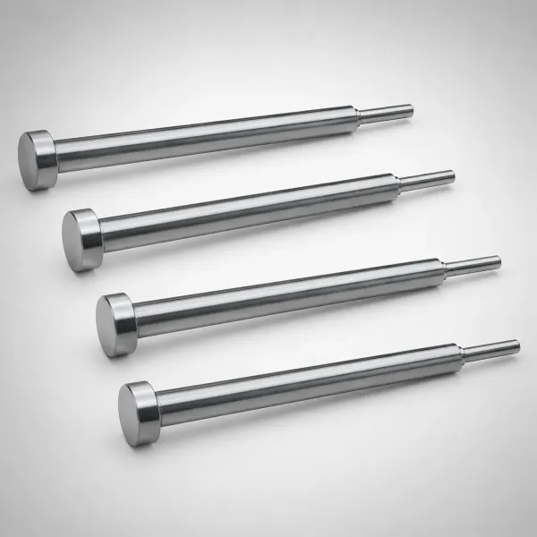
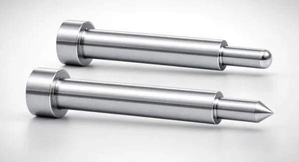
The locating pin is the mold feature that decides insert position. The pin pilots through the insert bore with a clearance near 0.05 mm, typical, and seats the insert on a shoulder or depth stop. A 1 to 2 degree taper on the pin entry lets the loader drop the insert without jamming. Position repeatability of ±0.05 mm is realistic with a solid pin on a stable seat.
The thread region needs protection from melt. A thread protection pin extends into the insert bore and seals against the first internal threads so plastic cannot enter. Seal lands hold 0.02 to 0.05 mm clearance, typical, and flash that reaches the threads turns the insert unusable. Venting through the pin annulus lets trapped air escape as the melt wraps the OD.

Wear decides how long the pin survives. Insert loads land on the pin tip thousands of times, so pins run on through-hardened tool steel at 58 to 62 HRC, typical. DieStrike hardens insert-mold cavities to HRC 62, and critical pin geometry is machined to ±0.002 mm. A 16-cavity tool multiplies pin wear by 16, which puts pin material and coating on the DFM list.
The nest or pin also must survive the closing force. Melt pressure of 500 to 1,000 bar, typical, presses the insert against the pin during fill. A pin that yields shifts the insert and ruins the shot. Pin diameter, support length, and steel grade come from the mold design review, not from the part drawing.
The Cycle Cost of In-Mold Loading
Time in the cycle is the first cost. Manual loading of a multi-insert tool typically runs 8 to 20 s per cycle, while a robot places the same inserts in 2 to 4 s. A base cycle of 30 s with two molded inserts grows by 6 to 16 s at 3 to 8 s each. That is a 20 to 50% loss of machine capacity before any other variable moves.
The capacity loss compounds at high cavity counts. A 32-cavity tool that would run 12 shots per minute drops toward 8 shots per minute when 6 s of loading enters every cycle. A 10 s addition on a 30 s cycle adds 33% to machine time on any program. That percentage decides whether automation pays.
Automation absorbs part of the hit. A vibratory bowl feeds inserts at 60 to 120 pieces per minute, typical, and a robot drops them into the tool during the previous shot's cooling. Loaded in parallel with cooling, the added time shrinks toward the robot stroke of 2 to 4 s. The tool then needs lifters or shuttles to present the nests, which raises mold cost by a typical 20 to 40%.
Lead time also stretches. An automated insert handling package adds design and build scope, so DieStrike quotes molded-in insert tools inside the standard 2 to 5 week window when the automation is defined at RFQ. Late changes to the loading method push both delivery and cycle risk.
Heat-Set Inserts: The Post-Molding Route
Heat-setting is a press operation, not a molding operation. A heated tip or an ultrasonic horn brings the insert to 260 to 430 °C, typical, and drives it into the molded bore. The boss bore is molded 0.1 to 0.3 mm larger than the insert OD, typical, so the hot insert seats without cracking the wall. Melt reflows around the knurl and freezes in seconds.
The mold does almost nothing special. The cavity carries a standard boss core with draft of 0.5 to 1 degree, typical, and the bore depth holds the insert seating tolerance. No locating pin, no thread seal, and no automation nest live in the steel. Tool cost sits at the low end of the range, and the molding cycle stays at the plain part cycle.
The cost moves off the press instead. Each insert needs one press stroke of 1 to 3 s, typical, plus handling, and the secondary station needs floor space and an operator or a small robot. Multi-insert parts run through the station once per insert or once per part with a multi-head press. The molding line gains throughput while the assembly line gains a step.
Heat-set also tolerates repair. A stripped insert can be re-pressed once with a new insert in a second 1 to 3 s stroke, and a part with a damaged bore can often be reworked instead of scrapped. Molded-in failures normally scrap the whole part because the insert is fused inside the wall. That difference matters at first article and in the field.
Pull-Out and Torque: Reading the Numbers
Bond strength is the headline number. A heat-set insert typically reaches 40 to 70% of the molded-in value, because only the reflowed ring of the boss locks the knurl. A molded-in insert is wrapped by the full melt flow, so shrinkage locks the complete knurl profile. The 40 to 70% band comes from supplier guidance and molding trials, not from a single formula.
Datasheet discipline decides whether either route passes. Insert suppliers publish pull-out force and retention torque for M2 to M8 brass inserts by knurl type, bore size, and plastic grade. The engineering team must pull the value for the exact insert, not the value for a similar part. Qualification runs 5 or more samples at a defined pull rate and compares the average to the datasheet minimum.
Knurl geometry sets the ceiling for both routes. Diamond knurls give grip in every direction, straight knurls resist axial pull, and hexagonal or through-hole profiles add rotation resistance. Molded-in plastic fills every valley because the melt flows around the whole OD. Heat-set reflow fills only the annulus near the boss wall, which is why the supplier band sits at 40 to 70%.
Test the joint the way the part is used. A torque-out check at 0.5 N·m on an M3 insert, a pull-out test in the axis of screw assembly, and a thermal cycle at 120 °C for 500 cycles cover the field loads most housings see. The datasheet gives the room temperature number, and the trial gives the derated one.
Boss Design Rules for Heat-Set Inserts
Boss wall thickness is the first rule. A post-molded boss needs 0.8 to 1.5 mm of wall around the insert, typical for M2 to M5 sizes, before the heated insert can displace melt without cracking. Thinner walls split on press-in, and thicker walls invite sink marks on the opposite face. The outside diameter counts from the insert OD plus two wall thicknesses.
Height and depth follow the insert. The boss height should match the insert length, and the bore depth should add 0.3 to 0.5 mm of clearance, typical, so the insert seats at a controlled depth. A deeper bore lets the insert bottom on the boss floor, which protects the part face from witness marks. Bore depth tolerance of ±0.05 mm is practical in a production tool.

Distance rules protect the wall. Insert suppliers publish minimum spacing from the insert axis to part walls and to neighboring inserts, and 1.5 to 2 mm of plastic between features is a common starting point. Gussets at 0.4 to 0.6 times the wall thickness, typical, stiffen a tall boss against press-in force. Draft on the boss OD runs 0.5 to 1 degree per side, typical, for clean ejection.
Crystalline resins demand the most care. PA66 and POM shrink 1.5 to 2.5%, typical, and pull the boss inward as they cool. The heat-set press then re-melts that stressed wall, and a thin boss can crack on re-freeze. A 30% glass-filled grade cuts the shrink to 0.3 to 0.7%, typical, which stabilizes the bore. The wall ratio logic follows the boss rules in our ribs and bosses design guide.
Part and Mold Rules for Molded-In Inserts
The same wall numbers apply on the part side of a molded-in insert. Keep 0.8 to 1.5 mm of wall around the insert, typical, and add ribs where the screw load is high. The difference is that plastic freezes around a cold brass insert, so thin walls freeze early and short-fill the knurl. Gate placement near the boss keeps melt moving until the knurl fills.
Cooling is a mold design input, not just a process note. Brass conducts heat near 120 W/m·K, typical, against about 0.25 W/m·K for unfilled nylon, so the insert pulls melt heat out of the boss region. The cooling layout keeps the boss zone at the mold temperature set in the DFM, typically 80 to 120 °C for PA grades. A 10 °C swing at the boss changes fill and freeze enough to move the bond.
Venting protects the knurl fill. Air trapped between the insert OD and the melt must escape through the pin annulus or dedicated vents, with typical PA vent depths of 0.02 to 0.03 mm. Short shots on the knurl look like full parts and fail pull-out at 60 to 80% of target. Vent checks belong in the mold trial report, not in the field.
Every insert feature above goes into the DFM review before steel cutting. DieStrike returns DFM feedback within 24 hours and flags pin clearance, vent depth, and gate position with measured values. The review also sets the loading method, which decides the automation features in the mold. Send the part model and annual volume, and the mold design and DFM service returns a route recommendation.
Molded-In vs Heat-Set Inserts: Side by Side
At a 30 s cycle with two M3 inserts, molded-in adds 6 to 16 s while heat-set adds zero. The table compares the routes across the factors that change the tool and the program.
| Factor | Molded-In Insert | Heat-Set Insert |
|---|---|---|
| Relative bond strength | 100% baseline, full knurl encapsulation by melt | 40 to 70% of molded-in, typical |
| Time in molding cycle | 3 to 8 s per insert, typical | None, staking runs after ejection |
| Mold complexity | Locating pin, thread seal, vents, automation nests | Standard cavity with plain boss core |
| Mold cost impact | 20 to 40% premium, typical, for automated handling | Lowest route, no special tool steel |
| Loading automation | Robot or vibratory bowl at 60 to 120 parts per minute feed | Heat stake or ultrasonic press, off line |
| Position accuracy | ±0.05 mm typical via solid pin seat | Fixture dependent, part level control |
| Typical resins | PA66, PA6T, PBT, PC, ABS, LCP | PC, ABS, PA with 0.8 to 1.5 mm boss wall |
| Main risks | Insert shift, thread fill, pin wear | Boss crack, low pull-out, added station labor |
← swipe to scroll →
Table note: Bond strength, cycle, and mold cost figures are typical industry values. Pull-out force and retention torque for M2 to M8 brass inserts must come from the insert supplier datasheet for the exact size, knurl, and plastic grade.
Neither route wins on every axis. Molded-in carries the strongest bond and the cleanest part flow, while heat-set carries the simplest tool and the fastest cycle. A joint that must survive 10,000 assembly cycles at 80 °C pulls most programs toward molded-in. The decision falls to the load case, the volume, and the resin, covered next.
Material Choice: Shrinkage and Crack Risk
Resin choice shifts the balance of the two routes. Amorphous resins such as PC and ABS shrink 0.4 to 0.7%, typical, so bosses stay relaxed and heat-set reflow behaves predictably. Crystalline resins such as PA66 and POM shrink 1.5 to 2.5% and clamp hard on anything inside the boss. Molded-in inserts use that clamp as strength, while heat-set inserts must fight it during re-freeze.
Glass filler changes the numbers. PA66 with 30% glass shrinks 0.3 to 0.7%, typical, cuts the crack risk, and raises the heat deflection temperature toward 240 °C. Filled grades also flow less, so the mold needs slightly deeper vents and a gate sized for the higher viscosity. The knurl fill check at trial matters more with filled material.
High-temperature applications favor molded-in. A connector housing at 150 °C continuous air, common near EV battery junctions, pushes PA6T or PPA inserts into the tool. Heat-set joints in the same resins lose a larger share of their 40 to 70% bond as the plastic approaches its heat deflection point. Molded-in geometry keeps the anchor at full depth in the strongest material.
The mold temperature spec belongs in the same review. Crystalline resins run mold temperatures of 80 to 120 °C, typical, to control the shrinkage band around the insert. A stable cavity temperature keeps the boss bore within ±0.02 mm across a 16-cavity tool. That bore control decides whether heat-set inserts seat at the same depth on every cavity.
Volume, Automation and the Decision Path
Volume picks the automation level, and automation picks the route economics. Below roughly 50,000 parts per year, heat-set usually wins because the tool is simple and the secondary station is cheap. From 50,000 to 250,000 parts, molded-in with manual or tray loading stays competitive on bond-critical joints. Above 500,000 parts, a robot-fed molded-in system earns its 20 to 40% mold premium through cycle and labor savings.
Scrap cost tilts the table at high volume. A molded-in shift at 1 part in 1,000 on a 500,000-part program scraps 500 parts before the fault is caught. Heat-set scrap usually lands at the press station, where it costs a part and a few seconds, not a full molding cycle. Insert presence sensors in the tool catch molded-in faults on the first bad shot.
Thread position flexibility can decide mid-program changes. Heat-set tools let the team change insert size with a new boss core, while molded-in tools need matching pin, seal, and nest changes. A molded-in change from M3 to M4 touches the pin, the seal land, and the nest, typically 6 steel features. Check the revision plan before the mold is cut.
The decision path is short. Start with the datasheet pull-out and torque requirements for your M2 to M8 size, derate for temperature and repeated assembly, then compare cycle cost at the forecast volume. Route the choice through the DFM review so the tool, not the operator, carries the risk. DieStrike reviews insert tool designs with measured pin clearances and vent depths, and returns feedback within 24 hours.
FAQ: Molded-In vs Heat-Set Inserts
Q1. Which anchoring method is stronger?
Molded-in inserts bond strongest because melt encapsulates the full knurl, giving the 100% baseline. Heat-set inserts reach 40 to 70% of that value, typical, because only the reflowed boss ring locks the knurl. Pull-out and torque numbers for M2 to M8 brass inserts come from the supplier datasheet.
Q2. Can an existing mold switch from molded-in to heat-set?
Not without tool changes. The boss bore must open 0.1 to 0.3 mm, typical, to seat a heated insert, and the locating pin, thread seal, and nests must come out of the cavity. Changes of that scale usually mean a new insert cavity core or a formal mold revision.
Q3. When does heat-set beat molded-in on cost?
Below roughly 50,000 parts per year, the simpler tool and untouched molding cycle usually win. Two molded-in inserts add 6 to 16 s to a 30 s cycle, typical, which heat-set keeps entirely out of the press. The secondary press cost then decides the comparison.
Q4. Which resins crack around heat-set inserts?
Crystalline resins carry the risk. PA66 and POM shrink 1.5 to 2.5%, typical, and the re-freeze after staking can split a boss thinner than 0.8 mm. PC and ABS at 0.4 to 0.7% shrink, typical, and 30% glass-filled PA at 0.3 to 0.7% shrink are far safer.
Q5. Is molded-in automation mandatory?
No. Manual loading runs 8 to 20 s per cycle, typical, and suits programs under 250,000 parts. Above 500,000 parts per year, a robot-fed line at 2 to 4 s per load usually pays for its mold premium.
The Bottom Line
Pick molded-in when the joint must survive vibration, heat, or repeated assembly above 10,000 cycles. Pick heat-set when the tool budget and cycle time dominate a lower-load joint. Run the datasheet numbers for your M2 to M8 size, and review the route with a mold maker before steel is cut.
For a 24 hour DFM review of your insert program, contact DieStrike.
KEEP READING
Related Reading
How to Design Insert Molds
System rules for metal insert tools: retention nests at 0.02-0.05 mm fits, manual loading at 8-20 s per cycle, and the heat sink effect of brass.
Read articleArticleInsert Molding vs Overmolding
Two tool families compared by placed part, retention design, sealing lands and heat management, with the failure sets that drive each steel layout.
Read articleArticleHow to Design Ribs and Bosses: Wall Ratios, Draft and Sink Control
Boss geometry that supports inserts: walls at 0.4-0.6x wall thickness, OD near 2x bore, draft of 0.5-1.5 degrees per side and sink control.
Read articleServiceMold Design & DFM
DFM review within 24 hours: gate position, vent depth, locating pin clearance and insert loading method checked against your part and volume.
Read articleNEXT STEP
Ready to Start Your Mold?
Send us your element dimensions or part numbers — our team responds within 24 hours with pricing and lead time.

Written by
Ray ChanMold Buyer's Guide Author · Precision Mold Manufacturing Specialist. Ray helps global importers, distributors and OEMs source factory-direct molds and mold parts.