
Insert Molding vs Overmolding: How to Choose
Table of Contents
A connector program spent 9 weeks proving a soft-touch overmold on a housing that only needed a brass thread. The TPE layer looked right, then failed peel at 0.8 N/mm. The engineer re-read the drawing: the customer asked for a threaded insert, not a grip.
The mold was re-cut as an insert tool and the thread survived 12,000 cycles. The process was right the whole time. The choice was wrong.
Insert molding and overmolding both build multi-material parts, and buyers mix them up because both put one material into contact with another. The two processes answer different questions. Insert molding embeds a pre-made component, usually metal, inside the molded part.
Overmolding applies a second polymer over a part that was molded first. DieStrike builds both tool types under IATF 16949. This guide tells a mold buyer which process a part needs before the RFQ goes out.
This article is a decision guide, not a process tutorial. Deep how-to coverage lives in two companion guides. The insert mold design guide covers retention nests and loading. The overmolding design guide covers bond chemistry and tooling.
Here we compare the two on the questions buyers ask: what each adds, which one wins on a given function, and where the cost goes. Shrinkage match and retention rules close the comparison. Figures labeled typical are industry practice ranges. Verify your grade datasheet and your program volume before cutting steel.
The Snapshot
- Insert molding adds a pre-made component: a metal or plastic part placed in the cavity, with plastic molded around it so the plastic becomes the carrier.
- Overmolding adds a second material: a polymer layer molded over an already-molded substrate, joined by chemical or mechanical bond.
- One-line difference: insert molding adds a component, overmolding adds a material.
- Manual insert loading runs 8-20 s per cycle typical, automated loading drops it to 1-3 s.
- Matched TPE over PP bonds at 2-10 N/mm peel with no primer; PA and PC substrates need flame, plasma, or primer treatment.
- Shrinkage mismatch between substrate and overmold runs 0.3-2.5% typical; hold the delta near 0.3-0.8% or add 0.3-0.8 mm mechanical locks.
Insert Molding and Overmolding: Two Processes Defined
Insert molding places a pre-made component into the mold cavity, then closes the tool and injects plastic around it. The component is the insert, and it can be metal or molded plastic. Common inserts are threaded brass or steel nuts, copper terminals, contact pins, magnets, and EV busbars. The molded plastic locks around the insert and becomes the structural carrier of the part.
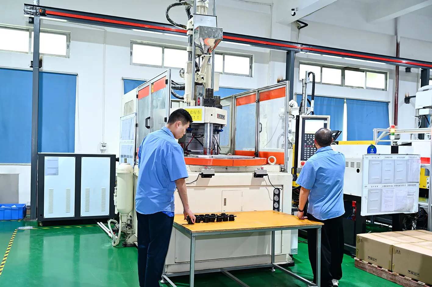
Insert molds often run on vertical presses rather than horizontal ones. The operator or robot places the insert from above into the open cavity. Gravity holds small parts in the nest while the mold closes. Typical manual loading takes 8-20 s per cycle, which is why the process is cost-sensitive to part count. Threaded inserts, terminals, and busbars are the classic jobs: functions that plastic alone cannot deliver.
Overmolding molds a second polymer layer over a substrate that was molded in an earlier step. The substrate is the first shot, and the overmold is the second. The classic example is a TPE soft-touch grip over a rigid PP or ABS handle. Seals and gaskets over-molded onto housings follow the same logic, and so do two-shot parts molded inline on a rotary platen tool.
Overmolding works only when the second material bonds to the first, or when geometry holds it in place. Bonding is chemical when the two melts fuse at the interface, and mechanical when the design adds ribs, undercuts, or through-holes. A matched TPE bonds to PP at 2-10 N/mm peel without primer. That is why soft-touch PP handles are the most common overmold application in the market.
Terminology blurs the boundary in RFQs. Some molders call any second-material step overmolding, even when it encapsulates a metal stamping, and call a two-shot soft-touch job insert molding. Industry convention separates them by what is added: a component versus a material. State it in the drawing notes, because the mold quote, the process FMEA, and the automation plan all follow that one line.
What Each Process Actually Adds
Frame the decision by what each process injects into your program. Insert molding adds three things: the pre-made component itself, a retention feature that holds it, and a loading step in every cycle. The insert is a purchased part with its own cost and supply chain. Retention comes from the part geometry, not the plastic: undercuts, knurls, flats, or through-holes stop pullout and rotation.

The loading step is the hidden program cost. Manual placement at 8-20 s per cycle dominates the cycle time on small parts, and it adds a labor line to every unit. Automated loading with a bowl feeder, pick-and-place robot, or shuttle table cuts that to 1-3 s per insert. The feeding system is capital that only high volume justifies. Retention nests in the cavity are machined to 0.02-0.05 mm clearance typical, so insert position repeats shot after shot.
Overmolding adds a different stack: a bond, a first-shot mold, and a second-shot mold. The bond is the engineering deliverable, and it lives or dies on material pairing. The tooling is two molds, or one two-shot tool with a rotary platen or core-back station. There is no per-cycle loading step, because the substrate is molded inside the same production flow.
The one-line difference drives every later decision. Insert molding adds a component with mechanical retention. Overmolding adds a material with chemical or mechanical bonding. If the part needs a metal thread, a current path, or a magnet, the decision is already made. If it needs a soft layer, a seal, or a second color over the same plastic family, overmolding is the only process that fits.
When Insert Molding Wins
Insert molding wins when the part must carry a function that plastic cannot. Electrical conductivity is the clearest case. A copper terminal or busbar carries current through a molded housing because the metal path is embedded, and plastic is the insulator that surrounds it. EV battery modules use insert-molded busbars by the thousands. A molded plastic carrier with a stamped copper path beats a bolted assembly on weight, cost, and contact resistance.
Threads are the second case. A brass or steel insert molded into a PA or PBT boss carries a screw repeatedly without stripping. A plastic thread fails after a few assembly cycles. Molded-in threaded inserts eliminate the separate press-in or ultrasonic insertion step, which runs 0.3-1.0 s per insert on its own machine. Assembly elimination is the quiet win: one molded part replaces a part plus a fastener plus a labor step.
Retention is a mechanical design problem, and the rules are simple. Knurls, hex flats, and annular undercuts stop the insert from rotating in the cavity. Through-holes let plastic flow through and lock both faces, which is the strongest pullout defense for flat parts like busbars and contact plates. Insert design depth is covered in our insert mold design guide, which walks through nest fits, loading automation, and cycle math cavity by cavity.
Volume does not disqualify insert molding the way buyers assume. Manual loading at 8-20 s caps output near a few hundred parts per shift per press. Automated loading at 1-3 s puts insert molding into the same cycle league as straight molding, with feeders handling thousands of inserts per hour. The decision is automation cost versus labor cost, not process capability.
The savings show up in the BOM, not just the mold. One insert-molded connector body replaces a stamped contact, a separate insulator, and a crimp or weld step. Programs that quote insert molding against the assembled alternative usually land on fewer part numbers, fewer suppliers, and one molded quality record instead of three.
When Overmolding Wins
Overmolding wins when the added value is a surface or a seal, not a metal function. Soft-touch ergonomics is the flagship case. A TPE layer over a rigid PP or ABS handle gives grip, vibration damping, and a premium feel. Power tool handles, medical device grips, and consumer housings all run this way.
Sealing is the engineering case. An overmolded elastomer gasket on a housing flange replaces a separate rubber seal and its assembly step. The bond line becomes the seal line, and the two materials are fused in one production flow. Overmolded seals hold up where a pressed-in O-ring relaxes, because the TPE is molded to the substrate contour with no gap for creep to open.
Bond strength decides whether the design works, and it is a material-pairing problem. A matched TPE over PP bonds at 2-10 N/mm peel without primer, which is why PP is the forgiving substrate. PA and PC need surface preparation: flame, plasma, or primer raises the surface energy of the substrate so the melt wets it. Dyne levels near 38-44 mN/m are the typical shop-floor target before the second shot.
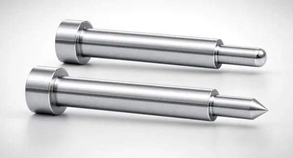
Overmolding carries no loading step, which is its automation advantage. Two-shot rotary platen tooling molds the substrate and the overmold in one machine cycle, with zero handling between shots. Cycle time adds only the second injection and its cooling, and the part never leaves the machine. For high volume, that inline flow beats insert molding's feeder complexity and the extra press. Two-shot architecture is a family of its own, detailed in our two-shot mold design guide.

Cost Drivers Compared: Loading vs Second Tool
The cost profiles point in opposite directions. Insert molding spends on the insert and on loading. Every insert is a purchased part with a piece price. Every cycle carries the loading penalty: manual at 8-20 s, or automated at 1-3 s plus feeder capital. The mold itself is a single-shot tool, which keeps tooling cost at baseline.
Overmolding spends on tooling and on validation. Two molds, or one two-shot tool with a rotary platen, typically runs 1.5-2.5 times the cost of a single-shot mold. Two-stage overmolding with pick-and-place adds a second machine and its floor space instead. Bond validation is a real line item: peel tests, dyne checks, and environmental aging trials all cost weeks and money before production release.
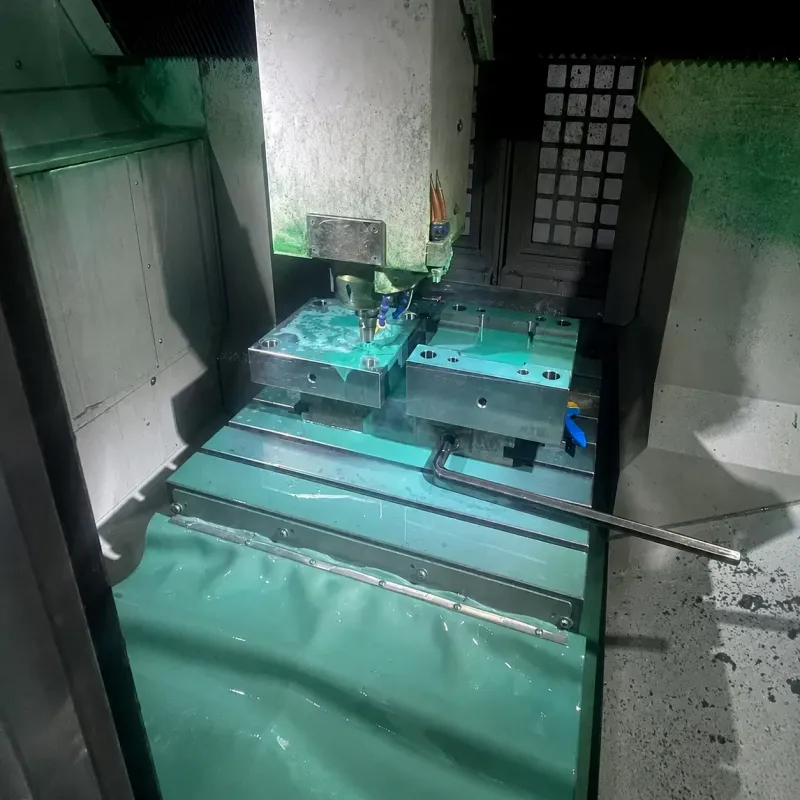
Compare the two at program level. A low-volume threaded part with a $0.10 brass insert and manual loading carries a small tool and a large labor line. The same part at 500,000 units justifies a bowl feeder, and the automated insert tool starts to look like straight molding with a feeder. A soft-touch handle at any volume carries no insert cost, but the two-shot tool premium of 1.5-2.5x must amortize across the run.
The break-even logic is simple. Insert molding wins when insert cost plus loading cost stays below the extra tooling and validation of overmolding. Overmolding wins when the part is high volume, the second material is cheap, and the tool premium spreads thin. Ask your molder for both quotes at your real annual volume, not at a guess. The two cost curves cross, and the crossing point is your decision.
Budget the feeding system early when you automate inserts. A vibratory bowl, orienting tracks, and a pick-and-place shuttle add weeks to the mold program. Insert position repeatability must be proven before first shots, even when the tool is unchanged. Buyers who defer the automation decision until after T1 sampling pay for the mold twice.
Shrinkage Match and Retention: The Engineering Core
Shrinkage is where both processes earn or lose their tolerances. Every polymer shrinks as it cools from melt to measurement temperature, and published mold shrinkage values for common resins run from about 0.3% to 2.5%. Semicrystalline resins like PA and POM sit at the high end. Amorphous resins like ABS and PC sit at the low end. Elastomers keep moving after ejection, which complicates the picture.
Overmolding couples two shrinking materials, and the mismatch is the risk. If the substrate and overmold shrink at different rates, the layer can warp the part, sink at the bond line, or peel. Industry practice holds the shrinkage delta near 0.3-0.8% between substrate and overmold. Beyond that range, or when the chemistry will not bond, add mechanical locks: ribs, undercuts, or through-holes in the substrate sized at 0.3-0.8 mm typical.
Insert molding couples a shrinking plastic to a metal that does not shrink in the cavity. The insert is dimensionally stable at mold temperature, so the plastic shrinks onto it and locks it tighter. That is why knurled and annular-groove inserts hold: shrinkage drives the plastic into the retention feature. The mold-side cost is the retention nest. It is machined at 0.02-0.05 mm clearance so the insert seats true and flash stays out.

Warpage follows unbalanced shrinkage on both processes. Inserted metal conducts heat out of the melt fast, so thick copper sections freeze the plastic around them at a different rate than thin walls. Overmolded TPE shrinks onto a rigid substrate that is already dimensionally set, which concentrates strain at the interface. CMM verification of the bond line after molding catches both problems before the tool leaves the shop.
DieStrike builds these tools with hardened cavity steel at HRC 62. Abrasive glass-filled compounds and long EV runs do not wear the nests or shutoff faces. The comparison below stacks the two processes on the numbers that decide the quote.
| Dimension | Insert Molding | Overmolding |
|---|---|---|
| What is added | Pre-made metal or plastic component | Second polymer layer over a molded substrate |
| Holding mechanism | Mechanical: knurls, undercuts, through-holes | Chemical bond plus 0.3-0.8 mm mechanical locks when needed |
| Typical parts | Threaded inserts, terminals, busbars, magnets | Soft-touch grips, gaskets, overmolded seals |
| Handling per cycle | Manual 8-20 s or automated 1-3 s loading | None inline on rotary platen; second press if two-stage |
| Tooling | Single-shot mold plus insert feeding | Two molds or 1.5-2.5x two-shot rotary platen tool |
| Material pairing | Any encapsulating resin over metal | Must bond: matched TPE-PP, prep needed for PA and PC |
| Shrinkage logic | Stable metal insert, plastic shrinks onto it | Mismatch 0.3-2.5%; hold delta near 0.3-0.8% |
| Electrical function | Metal current path embedded in plastic | Polymer to polymer only, no embedded metal path |
← swipe to scroll →
Table: Typical industry practice ranges for insert molding and overmolding. Values vary by resin grade, insert type, and automation level.
Decision Matrix: Questions That Pick Your Process
Run the part through these five questions in order. The first question that answers yes usually settles the process. When answers split across rows, the hybrid route in the notes below usually wins.
| Question | Process That Fits | Why |
|---|---|---|
| Does the part carry current or need a metal thread? | Insert molding | Only embedded metal delivers a reliable current path or stripping-resistant thread |
| Does it need a soft-touch surface or a molded-in seal? | Overmolding | TPE layer bonds to the substrate and forms the grip or gasket |
| Must a metal component be encapsulated so plastic carries it? | Insert molding | Busbars, magnets, and contacts need full plastic encapsulation |
| Is the base already molded plastic and the addition polymer-only? | Overmolding | Matched TPE-PP bonds at 2-10 N/mm with no primer |
| Is volume high enough that manual loading dominates cost? | Automate the insert or overmold | Feeder loading at 1-3 s or inline two-shot removes the labor line |
| Will the joint flex or seal under pressure or temperature? | Overmolding | Elastomer flexes where a rigid insert joint would crack or leak |
← swipe to scroll →
Table: Decision matrix for mold buyers. Answer in order; the first clear yes sets the process direction.
Hybrid parts exist and they are common in connectors and EV hardware. An overmolded seal around an insert-molded terminal is one mold with three stations: insert the metal, mold the housing, then overmold the seal. Each station follows the rules of its own process, and the tooling premium stacks. Send the drawing to a DFM review before quoting, because station count drives the mold cost more than any single feature.
FAQ: Insert Molding vs Overmolding
Q1. Can one part use both insert molding and overmolding?
Yes, and connectors and EV hardware do it routinely. The metal insert is placed first, the housing plastic is molded around it, and a TPE seal or grip is overmolded last. Each step follows its own retention or bonding rules. Mold cost stacks because every station is a tool or a mold stage, so the DFM review decides whether the hybrid pays for itself.
Q2. Does overmolding ever need an adhesive or primer?
Matched pairs bond without them. TPE over PP at 2-10 N/mm peel needs no adhesive when the chemistries are matched. PA and PC substrates have lower surface energy and typically need flame, plasma, or primer treatment before the second shot. Dyne levels near 38-44 mN/m are the common shop-floor check that treatment worked.
Q3. Is overmolding the same as two-shot molding?
Two-shot molding is the inline form of overmolding, run on a rotary platen or core-back tool in one machine cycle. Overmolding also covers two-stage flow where the substrate is molded, then moved to a second press. Both join a second material to a molded substrate. The tooling math differs, and rotary platen tools typically cost 1.5-2.5x a single-shot mold.
Q4. Which process is cheaper for a threaded insert part?
Insert molding is usually the answer, because a thread needs metal. The alternative is a thread molded in plastic, which strips after repeated assembly. Post-mold ultrasonic insertion runs 0.3-1.0 s per insert on a separate machine. Compare the molded-in insert tool against the two-step route at your real volume before deciding.
Q5. How do I stop a TPE overmold from peeling off the substrate?
Check three things in order. First, confirm the pairing: matched TPE over PP needs no primer, while PA and PC need surface treatment to 38-44 mN/m. Second, keep the shrinkage delta near 0.3-0.8% or add 0.3-0.8 mm mechanical locks in the substrate. Third, validate peel at 2-10 N/mm on trial parts, not on datasheets, because molded-in stress and gate placement shift real bond strength.
Q6. What wall thickness works for a soft-touch overmold?
Typical overmold walls run 0.5-3 mm, sized to the grip or seal function and the flow length of the TPE grade. Thin layers under 0.5 mm fill poorly on textured surfaces, and thick sections add cycle time. Draft the substrate so the overmold flow wraps cleanly, and vent the bond-line shutoff at shallow depths typical for elastomer grades.
The Bottom Line
Choose insert molding when the part needs a function only a pre-made component can carry. Think current paths, metal threads, magnets, or busbars that plastic encapsulates. The tool is a single-shot mold. The economics are insert cost plus the 8-20 s manual loading penalty. Automation at 1-3 s fixes the cycle when volume demands it.
Choose overmolding when the addition is a material: a soft-touch TPE layer, a molded-in gasket, or a seal over an already-molded plastic substrate. The 1.5-2.5x tooling premium replaces the loading step entirely. Bond strength at 2-10 N/mm peel decides whether the design survives production.
The question that settles most programs is the one-line difference: are you adding a component or a material? Ask it before the RFQ, confirm the shrinkage math at 0.3-2.5% before the mold design review, and let the decision matrix pick the direction. DieStrike builds both tool types under IATF 16949 across 120+ machines. Geometry holds ±0.005 mm standard and ±0.002 mm precision, and molds ship in 2-5 weeks. Connector programs run for customers including TE Connectivity, Amphenol, and Luxshare.
KEEP READING
Related Reading
How to Design Insert Molds: Retention, Loading and Cycle
Retention nests at 0.02-0.05 mm fits, manual loading at 8-20 s per cycle, and copper inserts at 390 W/m·K conductivity. The full insert mold design playbook.
Read articleArticleHow to Design Overmolding: Bonding, Shrinkage Match and Tooling
TPE and TPU overmolding with 2-10 N/mm peel targets, PP flame and plasma treatment, and 0.3-0.8 mm mechanical locks when shrinkage mismatch runs high.
Read articleArticleThermoplastic Elastomer (TPE) Injection Molding Guide
TPE family data from Shore 5A to 60D, a 170-230 °C melt window, and which substrates SEBS and TPV grades bond to without primer.
Read articleServiceMold Design & DFM
DFM review in 24 hours on insert and overmold tooling. Design for manufacturing feedback before steel is cut, at zero change-order cost.
Read articleNEXT STEP
Ready to Start Your Mold?
Send us your element dimensions or part numbers — our team responds within 24 hours with pricing and lead time.

Written by
Ray ChanMold Buyer's Guide Author · Precision Mold Manufacturing Specialist. Ray helps global importers, distributors and OEMs source factory-direct molds and mold parts.