
How to Design Insert Molds: Retention, Loading and Cycle | DieStrike
Table of Contents
A molded-in terminal that drifts 0.10 mm can scrap parts that passed every visual check. In a 16-cavity automotive connector tool, one shifted insert repeats the fault across all 16 cavities before an operator sees it. Sorting, rework, and a two-day toolroom stop routinely cost more than that week's production margin. Insert location failure is the most common reason insert molding tools return to the mold maker.
Insert molding places a preformed metal part inside the cavity before each shot. The mold must hold that part in position, seal around it, and survive thousands of load and unload cycles. This guide covers the mold-side decisions that decide success: retention design, loading method, heat management, sealing, shrinkage compensation, and wear control.
DieStrike designs and builds these molds under IATF 16949 with 120+ machines. Customers include TE Connectivity, Amphenol, Luxshare, and Dongshan Precision. A production injection mold ships in 2 to 4 weeks, and DFM feedback returns within 24 hours.
The Snapshot
- A 0.10 mm insert shift can scrap 16 cavities in a single shot. Connector terminal position specs typically run ±0.05 to ±0.15 mm.
- Manual insert loading adds 8 to 20 s per cycle, typical. A robot places the same insert in 2 to 4 s.
- Copper conducts heat at roughly 390 W/m·K. A 150 °C preheated 50 mm busbar grows about 0.08 mm before it seats.
- Plastic shrinks 0.5 to 2.5% around metal that shrinks near zero. Each wall must be compensated separately.
- Seal lands around inserts hold 0.02 to 0.05 mm clearances. DieStrike machines mold geometry to ±0.005 mm, with ±0.002 mm on critical features.
The sections below follow the order of a mold design review, from the first nest decision to the RFQ checklist.
Insert Molding vs Overmolding: Tool Design Differences
Buyers use the two terms loosely, but the tool designs differ sharply. Overmolding places a finished plastic part into the tool and molds a second plastic over it. Insert molding places metal into the tool: a stamped terminal, a copper busbar, a threaded insert, or a sleeve. The placed part is rigid, conductive, and dimensionally stable, so the mold must fight a different failure set.
An overmold tool protects a soft substrate from crush and melt-back. An insert mold tool locates a hard metal part against injection forces, then seals molten plastic away from its leads. The metal part will not deform under clamp pressure, but it can shift, tilt, and conduct heat out of the melt. Those three risks drive most insert tool geometry.
The table below compares the two tool families on the decisions that change the steel.
| Aspect | Insert Molding | Overmolding |
|---|---|---|
| Placed part | Metal: stamped terminal, copper busbar, threaded insert, sleeve | Plastic: molded housing, gasket frame, PCBA carrier |
| Retention design | Nest pocket or locating pin seats the part in the cavity | Substrate clamped between core and cavity on crush lands |
| Heat management | Metal draws melt heat, and preheat of 80-150 °C is typical for large parts | Resin limits mold heat, with melt-back risk above the substrate melting point |
| Flash risk | Along insert leads, sealed by 0.02-0.05 mm steel lands | At parting line and substrate edges |
| Dominant failures | Insert shift, lead flash, stress cracking at metal corners | Melt-back, crushed substrate, seal leakage |
| Cycle structure | Load time added to each cycle, with manual loading running 8-20 s typical | Substrate handling on the mold, with cycle closer to standard molding |
← swipe to scroll →
Table 1. Tool-side comparison of insert molding and overmolding. Values are typical industry ranges, not DieStrike specifications.
There is a third route: mold the plastic plain, then add the metal after molding. Ultrasonic insertion, heat staking, and press fits place standard threaded inserts in 0.3 to 1.0 s each, typical, with no nest tooling. The trade appears in service. Molded-in inserts carry pull-out and torque loads 2 to 4 times higher than pressed inserts in the same resin, typical. Only molded-in terminals can be sealed for fluid or gas tightness.
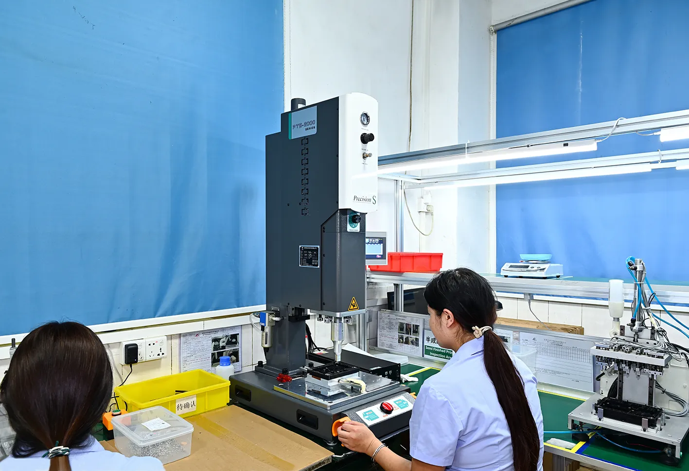
Post-mold insertion wins on low volumes, standard inserts, and zero tool complexity. Molded-in inserts win on sealed connectors, EV busbars, and any joint that must survive vibration at 105 to 150 °C underhood. Choose the assembly route before the mold design starts, because the nest, the gates, and the cooling layout all change.
Why Insert Retention Decides Mold Cost
Retention is the geometry that keeps the insert exactly where the drawing puts it during the shot. It decides mold cost because it decides cavity construction. A simple nest machined into a solid cavity block adds one pocket. A sliding retainer, a spring-loaded side lock, or a carrier-strip feed system adds plates, actuation, and setup time. The cost ladder is visible in the build hours.
A straight pocket is cut with the cavity and costs near zero extra. A pin-located round insert adds a drilled and bushed hole. A floating nest with springs adds a sub-plate and assembly. Reel-fed carrier transfer adds a feed mechanism, a trim station, and press synchronization. Each step raises the mold by roughly 5 to 15% of the base tool price, typical, and buys a different failure protection.
Retention also sets the tolerance story. The insert can only be as accurate as the seat that holds it. If the pocket runs 0.02 to 0.05 mm clearance, typical, the insert position repeats inside that band. If the insert rocks in a worn pocket, terminal position walks shot to shot, and the molded part fails its connector gauge. A mold that holds ±0.005 mm steel geometry cannot correct a loose seat.
At DieStrike, cavity steel is hardened to HRC 62 and pockets are verified before the mold leaves the floor. Mold geometry holds ±0.005 mm as standard and ±0.002 mm on critical features. The seat is designed on the drawing, not discovered at first trial.
Retention Methods Compared
Four retention families cover nearly every insert molding tool: machined nests, locating pins, knurled inserts, and carrier-strip transfer. Each locates the part differently, costs differently, and fails differently. The choice follows insert shape, quantity per cycle, and annual volume.
A machined nest is a close-fit pocket cut to the insert profile. The pocket floor carries the insert, and the side walls stop lateral movement. Pocket clearance of 0.02 to 0.05 mm is typical for stamped terminals and machined inserts. The nest mouth gets a 0.3 to 0.5 mm chamfer so the operator or gripper does not scrape the steel on every load.

Nest life depends on load abuse. Stamped terminals carry burrs of 0.02 to 0.08 mm on their cut edges, typical, and each burr scrapes the pocket mouth. Hardened nests at HRC 48 to 62 survive millions of loads. Soft P20 nests wear within thousands.
The nest clearance must also absorb thermal growth when the insert arrives preheated. Aluminum inserts at 150 °C need 0.05 to 0.10 mm more clearance than a cold insert, typical.
| Method | Position Repeatability (Typical) | Mold Cost Impact | Reliability Risk | Best Fit |
|---|---|---|---|---|
| Machined nest pocket | ±0.05 mm from pocket fit of 0.02-0.05 mm | Low, cut with the cavity | Mouth wear from burrs, then rocking after wear | Stamped terminals, busbars, simple shapes |
| Locating pin | ±0.10 mm typical, from pin fit of 0.02-0.04 mm | Low to mid, a drilled and bushed hole | Pin bends below 1.0 mm diameter, then wears | Round inserts, sleeves, threaded inserts |
| Knurled or serrated insert | Nest position, with knurl adding 0.2-0.4 mm grip | Low, knurl made on the insert | Knurl shears resin under service load | Threaded inserts, studs needing pull-out strength |
| Carrier-strip transfer | ±0.05 mm from strip pilot holes | High, with feed, trim, and cutoff tooling | Strip jams, curl, and trim burr | High-volume multi-terminal tools, millions of parts |
← swipe to scroll →
Table 2. Insert retention methods compared on repeatability, cost, and risk. All values are typical industry figures. Final specs depend on insert geometry and volume.
Locating pins suit round inserts and sleeves where a nest would hide the datum. The pin enters a hole in the insert, so position quality follows the pin-to-hole fit of 0.02 to 0.04 mm, typical. Pins below 1.0 mm diameter bend under injection force, so thin pins need support bushings or a stepped shank.
Knurled inserts trade position for grip. The knurl, typically 0.2 to 0.4 mm deep diamond pattern, locks into the resin and resists axial pull-out and torque. The knurl only works when the resin shrinks onto it, so shrinkage of 0.5 to 2.5% must pull the plastic tight around the knurl crests.
Carrier-strip transfer feeds terminals on a stamped strip through the mold, molds over them, then trims the bridge. Position comes from the strip pilot holes at ±0.05 mm, typical, and the cycle stays automatic. The tool cost lands highest, and it earns its keep only at high annual volumes.
Insert Loading: Manual, Tray, or Robot
Every insert spends time inside the mold or traveling to it, and that time belongs to the cycle. A standard molding cycle runs 20 to 40 s, typical. Insert molding cycles run 40 to 90 s, typical, because loading, closing, and clamp dwell all stretch. The loading method decides how much of that stretch is labor.
Manual loading adds 8 to 20 s per cycle for one to four inserts, typical. The operator opens the guard, places parts, and confirms the shot. On a 45 s cycle that is a 20 to 40% cycle penalty paid in labor every single shot. Manual loading also injects human variation. An insert seated 0.3 mm short of the nest floor molds a terminal at the wrong height.
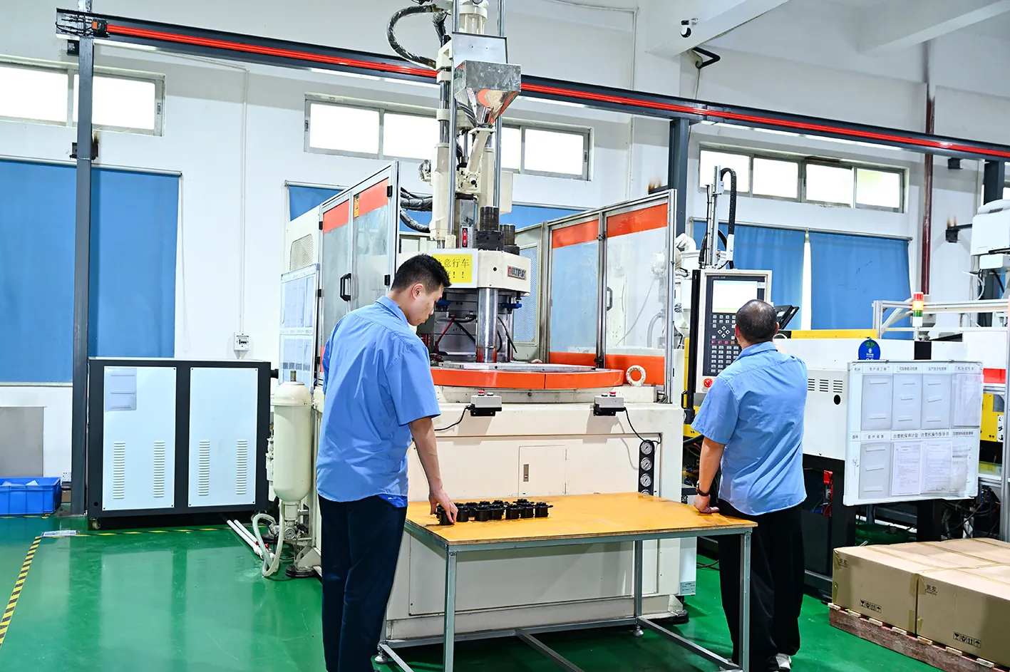
Tray loading cuts the human placement time to 3 to 6 s per cycle, typical. Inserts arrive pre-oriented in machined trays, and the operator or a pick arm transfers the whole set at once. Tray loading needs insert orientation control upstream. Tray accuracy of ±0.05 mm, typical, becomes the new position limit.
Robot loading places inserts in 2 to 4 s per cycle, typical, and removes the operator from the clamp area entirely. Vision-guided robots correct tray and feeder drift before placement. The robot pays back when cycle penalties compound. At 500,000 parts per year, saving 4 s per cycle returns about 550 production hours. Labor rates decide when automation wins.
Loading method also shapes mold design. Manual loading tolerates a top-loading nest with generous chamfers. Robot loading needs hard datums for the gripper and nests that accept straight-down placement without drag.
Whatever the method, the mold should carry a seat-presence check. A proximity sensor or vision check stops the press when an insert sits proud by more than 0.05 mm, typical. A missed insert shot turns an 8-cavity tool into an 8-way scrap event.
Heat Sink Effect of Metal Inserts
A metal insert is a heat sink standing in the melt path. Copper conducts at roughly 390 W/m·K, aluminum near 200 W/m·K, and steel near 30 W/m·K. Mold steel runs close to 30 W/m·K. A copper insert therefore draws heat roughly 13 times faster than the steel around it, and about 2,000 times faster than the plastic melt. The insert cools the resin that touches it, locally and early.
The effect shows up as premature freeze. Thin plastic lands over an insert freeze before the cavity packs. Expect short shots, weak knit lines, and sink at the far side of the insert.
The insert acts like an uncontrolled cooling channel placed exactly where the melt must stay hot. Automotive connectors in PA66, PBT, and PPS carry 0.2 to 1.5 mm plastic walls over their terminals, typical. The freeze risk is real on almost every geometry.
Quantify it before cutting steel. A 2 g copper busbar that rises from 30 to 200 °C absorbs about 130 J from the melt, by simple specific heat math. The insert takes that energy from the skin layer in the first second of fill. The adjacent resin solidifies early unless the insert arrives hot or the mold supplies heat nearby.
Preheating is the standard countermeasure. Inserts run at 80 to 150 °C, typical, which cuts the temperature gap to the melt and improves adhesion between resin and metal. EV battery busbars and sealed connector housings push this requirement hardest, and the mold must accept the hot part without binding. This is a mold-side design task, and it pairs naturally with the EV energy tooling programs that DieStrike supports.
Mold designers add insulation where the insert sits. An air gap or bushing between the insert pocket and the cooling circuit slows heat theft. The cooling line layout moves back from the pocket. Without compensation, the cavity surface around the insert runs 15 to 25 °C below the nominal mold temperature, typical. The offset shifts shrink and surface finish in that zone.
Shrinkage Around Metal Inserts
Plastic shrinks 0.5 to 2.5% linearly as it cools, depending on resin. Metal shrinks near zero. The two behaviors meet at every insert, and the mold must compensate each wall separately. This is the shrinkage compensation rule that insert tools cannot shortcut.
A free plastic wall between an insert and the part edge shrinks at the full resin rate. The cavity dimension then equals the drawing dimension multiplied by one plus the shrink rate. A steel-to-steel dimension between two inserts does not shrink. The metal holds the plastic, so the cavity distance between two nests matches the finished part distance with near zero compensation.
Designers who apply one shrink factor across the whole cavity get terminal spacing wrong by 0.1 to 0.3 mm on a 20 mm span, typical. That error is enough to fail a connector gauge.
The restrained shrink also stores stress. Semicrystalline resins such as PA66 and PBT shrink 1.5 to 2.5%, typical. When a rigid copper busbar blocks that shrink, the part cools under tension.
Sharp corners on the insert concentrate the tension into cracks. A 0.3 to 0.5 mm radius on every metal edge, typical, drops the stress concentration by a large margin. An encapsulation wall of 1.0 to 1.5 mm minimum, typical, gives the resin enough section to carry the stress without grazing.
Orientation adds a second layer. Glass-filled resins shrink less along the flow direction than across it, so the mold shrink factor differs by axis. Around an insert, the flow splits and recombines, which scrambles orientation and makes local shrink unpredictable. Mold fill simulation with the insert modeled as a solid body is the practical tool. The first-article CMM report at 23 ± 1 °C catches the residual error before production starts.
Sealing and Flash Control Around Inserts
Flash finds the path of least resistance, and inserts create paths. Molten resin wicks along terminal leads, under insert faces, and into the gap between insert and pocket. Flash on a terminal lead is not cosmetic scrap. It jams the mating connector and fails the electrical test. Sealing starts with the fit between insert and steel.
Steel lands around insert openings hold 0.02 to 0.05 mm clearance, typical, with a land length of 1.5 to 3.0 mm. The land must be straight and free of witness lines, because a 0.01 mm step becomes a flash line. Insert leads that exit the cavity get a pinch-off land on the steel. Keep the seal zone off the parting line wherever possible, so the clamp force acts directly on the land.
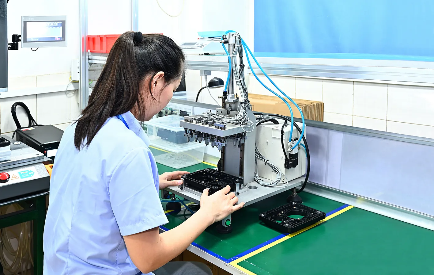
Terminal quality decides whether the seal holds. A stamped lead bent by more than 0.05 mm, typical, or carrying a burr lifts off the land and leaks melt. The RFQ should set insert flatness and burr limits before the mold is designed, because the land clearance budget is only 0.02 to 0.05 mm. A lead that arrives bent by 0.1 mm spends the whole budget before the shot starts.
Leak integrity is verified, not assumed, on sealed parts. Fuel, brake, and EV battery housings run air-decay leak tests at 30 to 60 kPa, with pass rates in the 0.5 to 1.0 cm³/min band. These figures are typical for the industry. The mold maker cannot certify that result, but the mold controls the seal land that makes it possible. This is why insert mold prints carry seal-zone tolerances at ±0.005 mm while the rest of the cavity runs looser.
Gate Placement Rules for Insert Molds
Gate placement in an insert mold answers one question first: where does the melt stream hit the insert? The stream should never fire straight at an insert face. Direct impingement pushes the insert downstream against its nest, bends thin pins, and jets against the metal surface. The terminal position error appears in the molded part before the flash cools.
Route the flow to sweep parallel to the insert axis instead. A gate on the cavity wall that fills past the insert, not into it, keeps the pressure balanced. When the insert stands tall in the flow path, a ring or film gate around it equalizes pressure on all sides. Typical for cylindrical inserts and round bushings, this symmetry prevents one-sided push.
Submarine gates suit insert tools because the vestige hides behind the terminal or in a recess. Gate land runs 0.5 to 1.0 mm, typical, and gate depth lands at 50 to 80% of the wall thickness. A gate placed within a wall of plastic over an insert creates a local hot spot that fights the heat sink effect. The designer places gates on the free-wall side and lets the flow close around the insert last.
Every insert splits the flow front, and the two fronts rejoin behind it as a weld line. Weld line strength runs 50 to 80% of bulk resin strength in unfilled materials, typical. It falls to 30 to 50% in glass-filled grades. Position the weld line off structural faces. Add a small overflow well behind the insert so the cold front material exits, and the weld line moves out of the loaded section.
Venting for Insert Pockets
Insert pockets are dead-end air traps. The insert seats at the pocket floor, and the air below and beside it has nowhere to go when melt arrives. Compressed air heats past the resin decomposition point and burns the surface, or it blocks fill and leaves a short shot at the pocket corner. Burn marks at pocket edges are the classic fingerprint of an unvented insert seat.
Vent the pocket through the cavity steel, not through the insert. Vent depths of 0.015 to 0.05 mm suit most thermoplastics, typical. The shallow end suits glass-filled grades, so resin cannot wick into the vent and flash. Each vent land runs 3 to 5 mm wide, typical. It steps into a 0.5 to 1.0 mm deep escape channel that leads to the atmosphere at the parting plane.
Position vents at last-fill points, which sit opposite the gate along each insert. A long thin terminal in a deep pocket may need two vents at the pocket ends. One central vent cannot empty both ends before melt arrives. Deep narrow pockets, common around EV busbar blades, benefit from vacuum venting. It pulls the pocket below atmospheric pressure before injection and removes the compression burn risk entirely.
Venting discipline pays in cycle stability. A mold that burns at the pocket burns the same pocket every shot, and the fix is steel work, not process tuning. DieStrike cuts vent detail on the hardened cavity and verifies vent depth in the mold record. The vent then survives the tool life it was designed for.
Insert Mold Steel and Wear Control
Insert molds wear faster than plain molds because metal slides against the cavity on every cycle. Stamped inserts carry cut-edge burrs of 0.02 to 0.08 mm, typical, and those burrs scrape the nest mouth as the insert loads. Copper and aluminum inserts gall on soft steel, welding material onto the pocket wall. Over 100,000 cycles the pocket mouth can open past the flash limit.
Wear control starts with steel selection. Insert tooling cavities run hardened tool steel at HRC 48 to 62, typical, and DieStrike hardens cavity steel to HRC 62. The nest mouth, the highest-wear zone, gets the same hardness as the cavity. A lead-in chamfer of 0.3 to 0.5 mm makes the insert slide instead of dig. Coating the nest with TiN or TiAlN, at 2,000 to 3,000 HV typical hardness, stops galling against copper and aluminum parts.
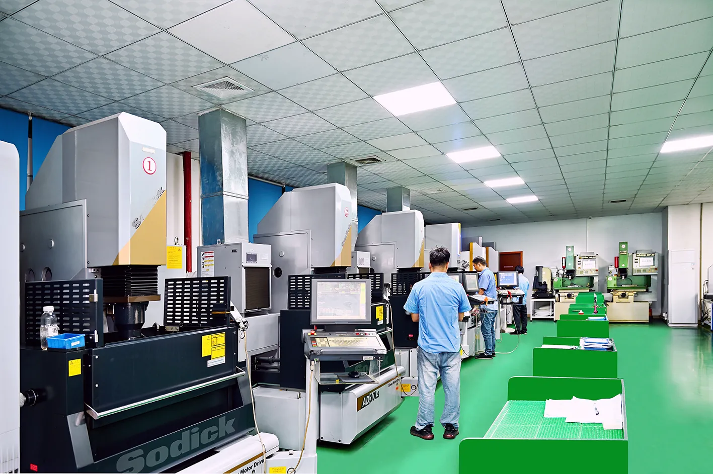
Milling cuts the pocket in the soft state, and heat treatment hardens it to HRC 62. Sinker EDM then finishes the pocket mouth, seal lands, and sharp corners in hardened steel. The EDM finish runs Ra 0.4 µm or better, typical, because a rough pocket face wears the insert and traps melt. Wire EDM cuts the terminal slots where the lead exits the cavity.
Design wear in as replaceable steel. Put the nest in a separate insert block, not in the solid cavity, so a worn pocket is swapped instead of welded. The cavity survives, and the replacement block is a new component, not a re-cut tool. DieStrike ships standard mold components in 3 to 7 days. Custom mold inserts follow the mold build schedule, so a wear block does not idle the program.
Schedule the wear check like a calibration. Every 50,000 to 100,000 cycles, typical, measure the nest mouth with a pin gauge or vision system. Compare it against the print clearance of 0.02 to 0.05 mm. When the mouth grows past 0.05 mm, flash follows within the next production run.
DFM Checklist for Your Insert Mold RFQ
An insert mold RFQ is only as good as the insert data it carries. Mold makers quote retention, loading, and sealing from the insert geometry, not from the plastic part alone. A complete insert data package gets a precise DFM in days. A package that says "insert per sample" gets assumptions, and assumptions become change orders.
Run the checklist below before the RFQ goes out. Each item maps to a steel-side decision, so missing items surface as cost or scrap later.
- Insert 3D model and material grade, including copper alloy, plating, and hardness. The alloy sets the thermal and galling behavior in the nest.
- Insert tolerances on the dimensions that touch the nest, typically ±0.02 to ±0.05 mm on critical features. State the burr limit on stamped edges, typically 0.05 mm max.
- Position tolerance of the insert in the molded part, typically ±0.05 to ±0.15 mm, so the mold maker can pick the retention method.
- Number of inserts per part and per shot. This drives nest count and decides manual, tray, or robot loading, with manual loading costing 8 to 20 s per cycle.
- Preheat requirement. State ambient or 80 to 150 °C so the pocket clearance and insulation bushing are designed for the hot part.
- Encapsulation wall thickness and metal edge radii. Minimums of 1.0 to 1.5 mm wall and 0.3 to 0.5 mm radii, typical, control stress cracking.
- Sealing and leak test requirement, including test pressure of 30 to 60 kPa typical. State the pass leak rate so seal lands are sized and verified.
- Annual volume and run size. Volume decides cavity count, retention automation, and whether standard or coated steels earn their cost.
- Loading method intent and any automation interface, so the mold carries the sensors and datums the loader needs.
DieStrike returns DFM feedback within 24 hours on a complete package. The mold design review flags retention risk, seal land feasibility, and loading cost before steel is ordered. That is where insert mold mistakes are cheapest to fix.
Frequently Asked Questions
Q1. Which retention method fits small stamped terminals?
A machined nest pocket is the standard answer. Pocket clearance of 0.02 to 0.05 mm, typical, holds terminal position near ±0.05 mm. For more than two terminals per part, or volumes above about one million parts per year, carrier-strip transfer removes the loading labor.
Q2. Do metal inserts really need preheating?
Small steel inserts often run at ambient temperature without visible defects. Large copper or aluminum parts behave differently. A busbar with a 2 g or larger section acts as a heat sink. Preheat of 80 to 150 °C, typical, stops premature freeze and improves adhesion. The nest clearance must absorb the insert's thermal growth.
Q3. What insert position tolerance can the mold hold?
The mold steel holds ±0.005 mm at DieStrike, with ±0.002 mm on critical geometry. The molded insert position is looser, typically ±0.05 to ±0.15 mm. The pocket fit, insert tolerance, and loading repeatability all stack up. Specify the pocket fit and the insert tolerance separately, and the position spec becomes achievable.
Q4. Molded-in or inserted after molding?
Molded-in inserts suit sealed connectors, high pull-out loads, and vibration duty. They carry pull-out strength 2 to 4 times higher than pressed inserts, typical. Post-mold ultrasonic insertion costs less in tooling and runs 0.3 to 1.0 s per insert, typical. It wins for standard threaded inserts at low to medium volume.
The Bottom Line
Insert mold failures trace back to seats, loads, and heat. A 0.10 mm shift, an 8 to 20 s manual load, or an unmanaged heat sink turns a connector program into scrap and downtime. Design the nest, the loader, and the thermal path on the drawing.
DieStrike builds insert molds to ±0.005 mm under IATF 16949, with DFM feedback in 24 hours and molds in 2 to 4 weeks. Send the insert package through the injection mold manufacturing line and get the retention review before steel is cut.
KEEP READING
Related Reading
How to Design Undercuts for Automotive Parts
Slides and lifters for automotive tooling: shut-off lands of 0.2-1.5 mm, draft angles, and release sequencing for zero-damage ejection.
Read articleArticleHow to Design Snap Fits for Injection Molded Parts
Snap-fit beams strain toward 2% limits, with undercut depths, draft, and ejection checks that keep molded parts crack-free.
Read articleArticleHow to Choose a Mold Temperature Controller
Match controller capacity to mold cooling load: flow rates of 5-20 L/min typical and temperature stability near ±1 °C.
Read articleArticleMold Venting: Depth, Location and Design Rules
Vent depths of 0.015-0.05 mm by resin, land widths, and placement rules that stop burns and short shots at last-fill points.
Read articleNEXT STEP
Ready to Start Your Mold?
Send us your element dimensions or part numbers — our team responds within 24 hours with pricing and lead time.

Written by
Ray ChanMold Buyer's Guide Author · Precision Mold Manufacturing Specialist. Ray helps global importers, distributors and OEMs source factory-direct molds and mold parts.